Bogen ProMatrix PM-3180 User Manual
Hide thumbs
Also See for ProMatrix PM-3180:
- User manual (50 pages) ,
- Brochure & specs (13 pages) ,
- Specifications (8 pages)

Related Manuals for Bogen ProMatrix PM-3180


Summary of Contents for Bogen ProMatrix PM-3180
- Page 1 5003-01.QXD 8/14/00 4:46 PM Page 1 ProMatrix Amplifier Model PM-3180 User’s Guide Part No. 54-5003-01 9605 Downloaded from: http://www.guardianalarms.net...
- Page 2 Rules. These limits are designed to out notice and should not be construed provide reasonable protection as a commitment by Bogen Communi- against harmful interference when cation, Inc. the equipment is operated in a com- Bogen Communications Inc.
- Page 3 5003-01.QXD 8/14/00 4:46 PM Page 3 ProMatrix Amplifier Model PM-3180 User’s Guide Owner’s Information Serial Number_________________________ Date of Purchase______________________ Place of Purchase_____________________ Address______________________________ ____________________________________...
-
Page 4: Table Of Contents
5003-01.QXD 8/14/00 4:46 PM Page 4 Contents Unpacking ........1 Introduction . -
Page 5: Unpacking
5003-01.QXD 8/14/00 4:46 PM Page 5 Unpacking The PM-3180 carton contains the following components: 1 - PM-3180 Amplifier Chassis 1 - Removable Control Panel* 1 - Wireless Infrared Remote Controller 2 - AAA Batteries 1 - 25-foot Control Panel Cable 1 - AC Power Cord 2 - Wall Anchors 1 - User Manual... -
Page 6: Introduction
5003-01.QXD 8/14/00 4:46 PM Page 6 Introduction Description The PM-3180 is a three-channel amplifier designed for multi-room applica- tions. It consists of three independent amplifiers, rated at 20, 60 and 100 watts and a programmable interface that lets you selectively assign priority levels to inputs and custom configure amplifier features. -
Page 7: Features
5003-01.QXD 8/14/00 4:46 PM Page 7 Introduction Features The PM-3180 has the following features: • Independent 20, 60 & 100 watt amplifiers in one package. • 2 Lo-Z balanced Mic inputs (Mic B can be configured as a 600-Ohm transformer balanced input for telephone paging applications). •... -
Page 8: Qxd 8/14/00 4:46 Pm
5003-01.QXD 8/14/00 4:46 PM Page 8 Quick Start This Quick Start section is intended to assist you in getting the PM-3180 up and running quickly so that you can become familiar with it. Important: When locating the amplifier, be sure to leave at least 2 inches of space on the right side of the unit to allow for fan exhaust. -
Page 9: Basic Wiring
5003-01.QXD 8/14/00 4:46 PM Page 9 Quick Start Basic Wiring 1. Temporarily set the AUX INPUT TRIM controls on the rear panel to their full counterclockwise position. Trims will be adjusted later. 2. Be sure that the voltage select switch is set correctly. Connect the power cord to the AC LINE INPUT 3. -
Page 10: Factory Programmed Configuration
5003-01.QXD 8/14/00 4:46 PM Page 10 Quick Start Factory Programmed Configuration When the amplifier is first powered up, the factory default settings are loaded. The factory default priority table is listed below. If you want to change any of these priority levels, you will have to use the ASSIGNMENT function in the programming mode. -
Page 11: Basic Operation
5003-01.QXD 8/14/00 4:46 PM Page 11 Quick Start Basic Operation This section will show you how to: • Apply power to the amplifier • Understand the Control Panel (See page 12 for full description) • Select which amplifier channel the control panel affects •... - Page 12 5003-01.QXD 8/14/00 4:46 PM Page 12 Quick Start To Control Volume Note: Changing any of the volume, bass or treble levels will effect all inputs associated with that amplifier channel. Turning up the volume for the current amplifier will cause other inputs assigned to that amp to play louder when they become active.
- Page 13 5003-01.QXD 8/14/00 4:46 PM Page 13 Quick Start To Select a Specific Input The amplifier is normally set to monitor input activity and, based on the default or installer-created priority table, automatically switches the proper input for each channel. You can override the priority switching feature of any amp to select a specific input to be on continuously.
-
Page 14: Aux Input Trim Adjustment
5003-01.QXD 8/14/00 4:46 PM Page 14 Quick Start Aux Input Trim Adjustment By adjusting the Trim controls as follows, inputs with different signal levels are set approximately equal within the amplifier. Important: You must properly set the Aux Input Trim Controls. Improperly adjusted trims can result in high distortion levels, poor volume balance between different inputs and false trigger- ing of inputs. -
Page 15: Rear Panel
5003-01.QXD 8/14/00 4:46 PM Page 15 Rear Panel 1. MIC A — XLR-type connector for balanced, LO-Z microphone input. Pin 1 is Gnd. 2. MIC B/TEL B — Input for Lo-Z balanced microphone. Software config- urable as a 600 transformer coupled paging interface. 3. -
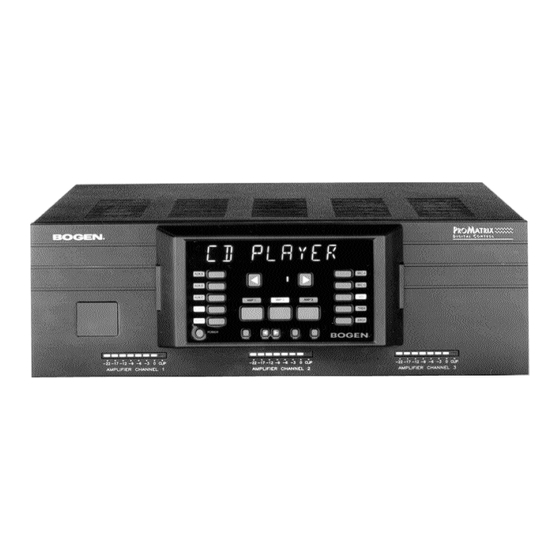
Page 16: Front Panel
5003-01.QXD 8/14/00 4:46 PM Page 16 Front Panel AUXA 1. Alphanumeric display area. 2. AUX A/B/C/D — Input selector buttons & indicators. 3. AUTO — Controls manual or automatic input selection. 4. POWER — Applies power to the amplifier. 5. AMP 1/2/3 — Amplifier Channel Selector Buttons 6. -
Page 17: Infrared Remote Controller
5003-01.QXD 8/14/00 4:46 PM Page 17 Infrared Remote Controller The infrared remote controller provides all of the functions of the front panel. Before using the controller, install two AAA-size batteries in the battery com- partment of the controller. Be sure to observe correct polarity. To use the controller, point the controller at the infrared receiver window on the left side of the front panel of the amplifier and press the desired button. -
Page 18: Wiring Information
5003-01.QXD 8/14/00 4:46 PM Page 18 Wiring Information Outputs Each amplifier channel has its own output terminal strip on the rear panel. Each terminal strip can handle a different type of speaker load. All amps can handle 70V & 25V distrib- uted or 8- or 4- loads. -
Page 19: Aux Inputs
5003-01.QXD 8/14/00 4:46 PM Page 19 Wiring Information AUX Inputs Unbalanced input sources other than microphones are connected to the AUX INPUT jacks. The output lead from the source must be terminated in an RCA-type plug. The input signal range is 100mVrms to 3Vrms and is adjusted using the AUX TRIM controls. -
Page 20: Mic Inputs
5003-01.QXD 8/14/00 4:46 PM Page 20 Wiring Information MIC Inputs Mic A Pin 1 is GND Pin 2 (+) Pin 3 (-) If Mic A has a push-to-talk switch, use these termi- nals for the switch connection (see Mic Precedence Setup in the Programming Section). -
Page 21: User Operation
5003-01.QXD 8/14/00 4:46 PM Page 21 User Operation The PM-3180 Control Panel The control panel is the interface between the user and the amplifier func- tions. Since there are three amplifiers and only one control panel, the PM- 3180 uses selector buttons, indicators and an alphanumeric display to pro- vide control over all amplifier functions. - Page 22 5003-01.QXD 8/14/00 4:46 PM Page 22 User Operation To Control Volume, Bass or Treble Note: Changing any of the volume, bass or treble levels will effect all inputs associated with that amplifier channel. Turning up the volume for the current amplifier will cause other inputs to play louder when they become active.
- Page 23 5003-01.QXD 8/14/00 4:46 PM Page 23 User Operation the current input was lowered by. This is because the levels set by the user are temporary and the PM-3180 always strives to maintain volume differ- ences set by the preset programming. Typically, this will only occur when the inputs or limits are set vastly different for the inputs assigned to an amp channel.
-
Page 24: Programming
5003-01.QXD 8/14/00 4:46 PM Page 24 Programming Enter Programming Mode The programming mode lets the installer custom configure the ProMatrix amplifier. The installer uses the programming buttons on the front panel or the infrared remote controller. Programming Buttons 1. Press PROG. The LED next to the button lights and the display shows 3 dashes. -
Page 25: Programming Menu
5003-01.QXD 8/14/00 4:46 PM Page 25 Programming Programming Menu The ProMatrix programming menu is illustrated below: Press PROG (or user-selected password) Assignment Set priority level for each amplifier-input combination Microphone Set precedence activation, ALC, phantom power Presets Set Mic B for telephone input Preset volume, bass and treble levels Vol limit Limit maximum volume for each amp-input combination... -
Page 26: Assignment
5003-01.QXD 8/14/00 4:46 PM Page 26 Assignment The ASSIGNMENT function lets you assign a priority levels to each amplifi- er-input combination. This function lets you create a variety of configura- tion schemes and obtain maximum versatility to meet application needs. The factory default priority levels are listed below: Input Factory Priority Level... - Page 27 5003-01.QXD 8/14/00 4:46 PM Page 27 5. Select a level and press ENT to save the selection (PROG LED will blink when selection has been entered). Important: You must press ENT after every change you make in order to save the new setting. This is true for all program- ming procedures.
-
Page 28: Mic Set Up
5003-01.QXD 8/14/00 4:46 PM Page 28 Mic Set Up This function lets you set the Microphone features: • Precedence Activation: N.O. = Normally Open - requires short between precedence terminals to activate mic N.C. = Normally Closed - requires short between precedence terminals to deactivate mic VOX = Voice Activated switch activation) •... -
Page 29: Presets
5003-01.QXD 8/14/00 4:46 PM Page 29 4. The display shows A ALC ON indicating that MIC A ALC status is ON.) 5. Press the NEXT or BACK buttons to select ON or OFF. 6. Press ENT to store the selection. A ALC ON 7. - Page 30 5003-01.QXD 8/14/00 4:46 PM Page 30 This feature lets the installer adjust the power-up volume, bass and treble of each amplifier-input combination. It also sets the relative volume levels between different inputs on a particular amplifier channel. The same inputs can have different volume and EQ settings on different amps.
-
Page 31: Volume Limit
5003-01.QXD 8/14/00 4:46 PM Page 31 5. Once you have set the desired volume for an input, press ENT. The PROG light will blink to indicate that the data was stored. 6. At this point, you can select another amp-input combination and repeat Steps 4 and 5 to set other volume levels. - Page 32 5003-01.QXD 8/14/00 4:46 PM Page 32 input combination to play at the maximum limit (default value is 25, full volume). This will normally be quite loud. Be careful that people are not next to speakers and that the power rating of the speakers is high enough to handle full amplifier power.
-
Page 33: Inhibit
5003-01.QXD 8/14/00 4:46 PM Page 33 Note 1: If the Volume Limit is set below the Preset volume level, the Volume Limit will control the power on output level. Note 2: Unassigned inputs for an amp can still have their Volume Limit set. -
Page 34: Aux Mute
5003-01.QXD 8/14/00 4:46 PM Page 34 INHIBIT appears on the display. 2. Press ENT to enter the function. 3. Select an amplifier by pressing one of the AMP buttons. 4. Press one of the control buttons (VOL, BASS or TREB). The display shows the current amplifier and the inhibit status for the selected con- trol. -
Page 35: Amplifier Link
5003-01.QXD 8/14/00 4:46 PM Page 35 to listen to the output in order to make the adjustment. 1. Enter programming mode and press the NEXT or BACK buttons until AUX MUTE appears on the display. 2. Press ENT to enter the function. The display shows the current amp- input combination and a two-digit number representing the volume level of the muted input. -
Page 36: Password
5003-01.QXD 8/14/00 4:46 PM Page 36 2. Press ENT to enter the function. The display shows the the current amplifier and link status (the default is Amp 1, Link In). 3. Select the desired amp by pressing the appropriate AMP button. 4. -
Page 37: Labels
5003-01.QXD 8/14/00 4:46 PM Page 37 3. Press the NEXT or BACK buttons to increment the first numeral from 0 to 9. 4. Press ENT to store the selection. 5. The second numeral flashes. Repeat steps 3 and 4. 6. The third numeral flashes. Repeat steps 3 and 4 for the third numeral. After entering the third numeral, the first numeral will begin to flash again. -
Page 38: Factory Defaults
5003-01.QXD 8/14/00 4:46 PM Page 38 ously entered label. The first character will be flashing. 3. If desired, select another input by pressing the appropriate button. 4. Press the NEXT or BACK buttons to scroll through the available charac- ters (A-Z, 0-9, —, [space]) and stop at the desired character. 5. -
Page 39: Testing & Troubleshooting
5003-01.QXD 8/14/00 4:46 PM Page 39 referring to Clear All (stored programming)? = No. 3. Press the NEXT/BACK buttons to toggle between NO or YS (for YES). 4. Press ENT to confirm the selection. 5. If YS is selected, the display asks U-SURE NO. for a second confirma- tion. -
Page 40: Troubleshooting
5003-01.QXD 8/14/00 4:46 PM Page 40 the priorities using ASSIGNMENT. Input Activity Test: Set all audio sources so that they are active. Manually select each input (see page 9) and check that the source plays through the amp. Result: This checks that all used inputs are active. If certain inputs do not play during normal operation, they may not have been assigned to an amp channel. - Page 41 5003-01.QXD 8/14/00 4:46 PM Page 41 • Unplug the unit, wait 5 seconds then restore power. • Display communication problem. Look for bent, broken or dirty pins on display panel rear connector. • Display cable broken or bent or dirty contacts in jacks. False triggering of non-active higher priority inputs •...
-
Page 42: Getting Help
• Reset password (see page 33). Getting Help Bogen has support available in case you have a problem with your ProMatrix amplifier. In order to make the most effective use of this service, please be sure to fill out and return the product registration card included with this unit. -
Page 43: Specifications
5003-01.QXD 8/14/00 4:46 PM Page 43 • Make sure that input sources are active. Microphones may require software setup (see instructions). For warranty service, refer to the product registration card. Our customer service support center can be reached at (201) 934-8500, extension 1310, weekdays from 9AM to 8PM, Eastern time. - Page 44 5003-01.QXD 8/14/00 4:46 PM Page 44 Mic Inputs: 200-ohms balanced Tel Input: 600-ohms transformer balanced Aux Input: 50Kilohms unbalanced Frequency Response & Distortion (20Hz to 20KHz): Amp 1: Aux Inputs: 20Hz to 20KHz ±2dB, <0.5% THD+N, direct output Aux Inputs: 70Hz to 20KHz ±2dB, <0.5% THD+N, transformer output Mic Inputs: 100Hz to 10KHz ±2dB, <0.5% THD+N, all outputs...
Need help?
Do you have a question about the ProMatrix PM-3180 and is the answer not in the manual?
Questions and answers