Bogen PM3180 Addendum User Manual
Hide thumbs
Also See for PM3180 Addendum:
- Specifications (8 pages) ,
- Brochure & specs (13 pages) ,
- Information (13 pages)
Table of Contents
Advertisement
Quick Links
Advertisement
Table of Contents
Troubleshooting

Related Manuals for Bogen PM3180 Addendum


Summary of Contents for Bogen PM3180 Addendum
- Page 1 User’s guide...
-
Page 2: Safety Information
Tel. 201-934-8500 • Fax: 201-934-9832 www.bogen.com The exclamation point within an equilateral triangle is intended to alert the user to the presence of important operating and mainte- Specifications subject to change without notice. nance (servicing) instructions. © 2012 Bogen Communications, Inc. 54-6710-10A 1206... - Page 3 Models PM-3000 & PM-3180 User’s Guide Part No. 54-5003-02 9707...
- Page 4 Rules. These limits are designed to out notice and should not be construed provide reasonable protection as a commitment by Bogen Communi- against harmful interference when cation, Inc. the equipment is operated in a com- Bogen Communications Inc.
- Page 5 Models PM-3000 & PM-3180 User’s Guide Owner’s Information Model Number Serial Number_________________________ Date of Purchase______________________ Place of Purchase_____________________ Address______________________________ ____________________________________...
-
Page 6: Table Of Contents
Contents Unpacking ........1 Packing List . -
Page 7: Unpacking
Unpacking Packing List The ProMatrix carton contains the following components: 1 - ProMatrix unit 1 - Removable Control Panel* 1 - Wireless Infrared Remote Controller 2 - AAA Batteries 1 - 25-foot Control Panel Cable 1 - AC Power Cord 2 - Wall Anchors 1 - User Manual 1 - Product Registration Card... -
Page 8: Introduction
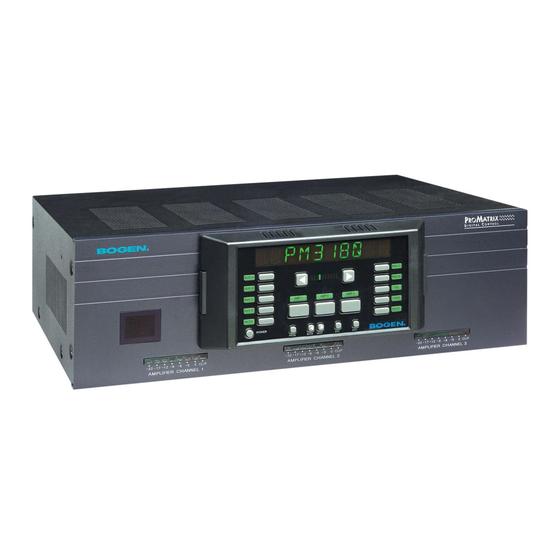
Introduction Description The ProMatrix products are designed for sound reinforcement/distribution in multi-room applications. The PM-3180 consists of three independent ampli- fiers, rated at 20, 60 and 100 watts. The PM-3000 is a three channel pre- amplifier unit designed to offer the flexibility for applications with power requirements that exceed the limits of the PM-3180. -
Page 9: Features
Introduction Features The ProMatrix units have the following features: • 2 Lo-Z balanced Mic inputs (Mic A is female XLR, Mic B is screw termi- nals). Mic B can be configured as a 600-Ohm transformer balanced input for telephone paging applications. •... -
Page 10: Quick Start
Quick Start This Quick Start section is intended to assist you in getting the ProMatrix unit up and running quickly so that you can become familiar with it. Important: Do not place any objects directly on top of the unit. Leave at least 2 inches of space above the unit to assure prop- er ventilation. -
Page 11: Basic Wiring
Quick Start Basic Wiring 1. Temporarily set the AUX INPUT TRIM controls on the rear panel to their full counterclockwise position. Trims will be adjusted later. 2. Be sure that the voltage select switch is set correctly. Connect the power cord to the AC LINE INPUT 3. -
Page 12: Factory Programmed Configuration
Quick Start Factory Programmed Configuration When the ProMatrix unit is first powered up, the factory default settings are loaded. The factory default priority table is listed below. If you want to change any of these priority levels, you will have to use the ASSIGNMENT function in the programming mode. -
Page 13: Basic Operation
Quick Start Basic Operation This section will show you how to: • Apply power to the unit • Understand the Control Panel (See page 12 for full description) • Select which channel the control panel affects • Change volume • Change Bass and Treble response •... - Page 14 Quick Start To Control Volume Note: Changing any of the volume, bass or treble levels will effect all inputs associated with that amp/channel channel. Turning up the volume for the current amp/channel will cause other inputs assigned to that amp/channel to play louder when they become active.
- Page 15 Quick Start To Select a Specific Input The ProMatrix unit is normally set to monitor input activity and, based on the default or installer-created priority table, automatically switches the proper input for each amp/channel. You can override the priority switching feature of any amp/channel to select a specific input to be on continuously.
-
Page 16: Aux Input Trim Adjustment
Quick Start Aux Input Trim Adjustment By adjusting the Trim controls as follows, inputs with different signal levels are set approximately equal within the ProMatrix unit. Important: You must properly set the Aux Input Trim Controls. Improperly adjusted trims can result in high distortion levels, poor volume balance between different inputs or false triggering of inputs. -
Page 17: Rear Panel Model Pm-3000
Rear Panel Model PM-3000 1. MIC A — Female XLR-type connector for balanced, LO-Z microphone input. Pin 1 is Gnd. 2. MIC B/TEL B — Screw terminal Input for Lo-Z balanced microphone. Software configurable as a 600Ω transformer coupled paging interface. 3. -
Page 18: Rear Panel Model Pm-3180
Rear Panel Model PM-3180 1. MIC A — XLR-type connector for balanced, LO-Z microphone input. Pin 1 is Gnd. 2. MIC B/TEL B — Input for Lo-Z balanced microphone. Software config- urable as a 600Ω transformer coupled paging interface. 3. MIC PREC — Microphone precedence terminals for contact closure activation. -
Page 19: Front Panel
Front Panel AUXA 1. Alphanumeric display area. 2. AUX A/B/C/D — Input selector buttons & indicators. 3. AUTO — Controls manual or automatic input selection. 4. POWER — Applies power to the ProMatrix unit. 5. AMP 1/2/3 — Amp/Preamp Channel Selector Buttons. 6. -
Page 20: Infrared Remote Controller
Infrared Remote Controller The infrared remote controller provides all of the functions of the front panel. Before using the controller, install two AAA-size batteries in the battery com- partment of the controller. Be sure to observe correct polarity. To use the controller, point the controller at the infrared receiver window on the left side of the front panel of the ProMatrix chassis and press the desired button. -
Page 21: Wiring Information
Wiring Information Outputs For PM-3000 Preamplifier Each preamplifier channel has its own balanced output terminals and unbal- anced RCA output jacks on the rear panel to handle different amplifier and signal processing inputs. 1. This figure shows wiring from the PM-3000 Note 1 Balanced Output to a standard XLR-type of... -
Page 22: Outputs For Model Pm-3180
Wiring Information Outputs For PM-3180 Amplifier Each amplifier channel has its own output terminal strip on the rear panel. Each terminal strip can handle a different type of speaker load. All amps can handle 70V & 25V distrib- uted or 8-Ω or 4-Ω loads. The 70V, 25V and 8-Ω... -
Page 23: Aux Inputs
Wiring Information AUX Inputs Unbalanced input sources other than microphones are connected to the AUX INPUT jacks. The output lead from the source must be terminated in an RCA-type plug. The input signal range is 100mVrms to 3Vrms and is adjusted using the AUX TRIM controls. -
Page 24: Mic Inputs
Wiring Information MIC Inputs Mic A Pin 1 is GND Pin 2 (+) Pin 3 (-) If Mic A has a push-to-talk switch, use these termi- nals for the switch connection (see Mic Precedence Setup in the Programming Section). Mic B Shield Push-to-talk switch pair. -
Page 25: User Operation
User Operation The ProMatrix Control Panel The control panel is the interface between the user and the unit functions. Since there are three channels (amp or preamp) and only one control panel, the ProMatrix uses selector buttons, indicators and an alphanumeric display to provide control of the overall functions. - Page 26 User Operation To Control Volume, Bass or Treble Note: Changing any of the volume, bass or treble levels will effect all inputs associated with that amplifier channel. Turning up the volume for the current amplifier will cause other inputs to play louder when they become active.
- Page 27 User Operation the current input was lowered by. This is because the levels set by the user are temporary and the ProMatrix always strives to maintain volume differences set by the preset programming. Typically, this will only occur when the inputs or limits are set vastly different for the inputs assigned to an amp channel.
-
Page 28: Programming
Programming Enter Programming Mode The programming mode lets the installer custom configure the ProMatrix unit. The installer uses the programming buttons on the front panel or the infrared remote controller. Programming Buttons 1. Press PROG. The LED next to the button lights and the display shows 3 dashes. -
Page 29: Programming Menu
Programming Programming Menu The ProMatrix programming menu is illustrated below: Press PROG (or user-selected password) Assi g nment Set priority level for each amplifier-input combination Mi c rophone Set precedence activation, ALC, phantom power Set Mic B for telephone input Presets Preset volume, bass and treble levels Vol li m i t... -
Page 30: Assignment
Programming Assignment The ASSIGNMENT function lets you assign a priority levels to each amplifi- er-input combination. This function lets you create a variety of configura- tion schemes and obtain maximum versatility to meet application needs. The factory default priority levels are listed below: Input Factory Priority Level MIC A... - Page 31 Programming 5. Select a level and press ENT to save the selection (PROG LED will blink when selection has been entered). Important: You must press ENT after every change you make in order to save the new setting. This is true for all program- ming procedures.
-
Page 32: Mic Set Up
Programming Mic Set Up This function lets you set the Microphone features: • Precedence Activation: N.O. = Normally Open - requires short between precedence terminals to activate mic N.C. = Normally Closed - requires short between precedence terminals to deactivate mic VOX = Voice Activated switch activation) •... - Page 33 Programming 4. The display shows A ALC ON indi- A ALC ON cating that MIC A ALC status is 5. Press the NEXT or BACK but- tons to select ON or OFF. 6. Press ENT to store the selection. 7. The display shows A PPS OFF indi- cating that the MIC A phantom A PPS OFF power is OFF.
-
Page 34: Presets
Programming Presets This feature lets the installer adjust the power-up volume, bass and treble of each amp/channel-input combination. It also sets the relative volume levels between different inputs on a particular amplifier channel. The same inputs can have different volume and EQ settings on different amps. Note: The system should be completely wired before making any of these adjustments, since the installer will normally want to listen to the output in order to make the adjustment. - Page 35 Programming Note: Press and hold arrow buttons to effect rapid changes in volume. Quick presses of the buttons will effect single-step changes in volume. 5. Once you have set the desired volume for an input, press ENT. The PROG light will blink to indicate that the data was stored. 6.
-
Page 36: Volume Limit
Programming Volume Limit This function sets the maximum volume level that a user can select for an amp/channel-input combination. Warning: The Volume Limit function will cause the amp- input combination in the PM-3180 to play at the maximum limit (default value is 25, full volume). This will normally be quite loud. - Page 37 Programming 6. Once you have set the desired limit for an input, press ENT. The PROG light will blink to indicate that data was stored. 7. Select another amp/channel-input combination and repeat Steps 4 and 5 to set other levels. Remember to press ENT after setting each level.
-
Page 38: Inhibit
Programming Inhibit This function lets the installer inhibit the user’s ability to change the preset volume and tone settings for a particular amplifier (Bass and Treble are always inhibited together as Tones. Pressing BASS or TREB does the same thing). Once set, the unit will not respond to commands from the front panel or remote controller for this amplifier channel in the user mode. -
Page 39: Aux Mute
Programming Aux Mute The Aux Mute allows paging over music. This function sets the volume level of each AUX input when a page is made. Upon completion of the page, the music level fades up to the previous level. The levels can be set differently for each Aux input on each amplifier. -
Page 40: Amplifier Link (Pm-3180 Only)
Programming Amplifier Link (PM-3180 Only) This function disconnects the power amplifier input from the preamp pro- cessing circuit and permits the addition of outboard signal processing equip- ment (such as an equalizer or ambient noise response unit) to the Audio Process RCA connectors on the rear of the amplifier chassis. -
Page 41: Password
Programming Password This function lets the installer change the program mode password. 1. Enter programming mode and press the NEXT or BACK buttons until PASSWORD appears on the display. 2. Press ENT to enter the function. PSWRD 000 The display shows the the cur- rent 3-digit password (The default is 0 0 0.) The first numeral will be flashing. -
Page 42: Labels
Programming Labels This function lets you modify the names displayed for the current input source during user operation. For example, you can change the name of AUX A TAPE 1. Enter programming mode and press the NEXT or BACK buttons until LABELS appears on the display. -
Page 43: Factory Defaults
Programming Factory Defaults This function lets you quickly erase all current configuration programming and return the amplifier to its out-of-box configuration. 1. Enter programming mode and press the NEXT or BACK buttons until DEFAULTS appears on the display. Press ENT to enter the function. CLR ALL NO CLR ALL NO The display shows:... -
Page 44: Testing & Troubleshooting
Testing & Troubleshooting Testing Assignment Test: Remove all audio sources from Aux inputs. Connect an active audio source to the lowest priority input for the current amp/channel. Move the active source through the inputs in the order of priority that was previously set. -
Page 45: Troubleshooting
Testing & Troubleshooting Vol Limit Test: Manually select an Aux or Mic input. Press and hold the right arrow button until the display stops incrementing. Result: The display stops incrementing at the volume limit for the particular input and amp combination (see page 30). Turn the Promatrix power off and then on to return volume levels to their initial preset levels. - Page 46 Testing & Troubleshooting Mic never active • Check that the type of precedence setting is correct for the application (See page 26). • If mic is a condenser type, check that phantom power is applied to mic input (see page 27) •...
-
Page 47: Getting Help
Getting Help Bogen has support available in case you have a problem with your ProMatrix. In order to make the most effective use of this service, please be sure to fill out and return the product registration card included with this unit. -
Page 48: Specifications
Specifications PM-3180 Power Output: Amp 1: 100 wrms Amp 2: 60 wrms Amp 3: 20 wrms Output Taps: 8-ohms, 25V and 70V transformer-coupled (balanced or unbalanced) 4-ohms direct coupled (unbalanced) Output Regulation: <2dB from no load to full load (all amps) Input Sensitivities: Mic Inputs: 750µVrms (no ALC) - Page 49 Specifications PM-3000 Outputs: 0dBV balanced outputs via screw terminal strips (all channels) 0dBV unbalanced outputs via RCA jacks (all channels) Maximum Output: 15dBV into 600Ω balanced Maximum Gain: 17.7dB (Vol. control @ 25) Input Sensitivities: Mic Inputs: 750µVrms (no ALC); Tel Input: 170mVrms;...
- Page 50 50 Spring Street • Ramsey, NJ 07446 www.bogen.com...
Need help?
Do you have a question about the PM3180 Addendum and is the answer not in the manual?
Questions and answers