Table of Contents
Advertisement
Quick Links
US and foreign patents licensed from Dolby Laboratories Licensing
Corporation.
SAFETY PRECAUTION FOR SERVICE MANUAL ........................................................................................................... 2
IMPOTANT SERVICE NOTES (FOR UK ONLY) ............................................................................................................... 3
SPECIFICATIONS ............................................................................................................................................................. 3
NAMES OF PARTS ........................................................................................................................................................... 4
OPERATION MANUAL ...................................................................................................................................................... 6
DISASSEMBLY .................................................................................................................................................................. 8
REMOVING AND REINSTALLING THE MAIN PARTS ................................................................................................... 11
ADJUSTMENT ................................................................................................................................................................. 14
NOTES ON SCHEMATIC DIAGRAM .............................................................................................................................. 35
TYPE OF TRANSISTOR AND LED ................................................................................................................................. 35
BLOCK DIAGRAM ........................................................................................................................................................... 36
SCHEMATIC DIAGRAM/WIRING SIDE OF P.W.BOARD ............................................................................................... 40
VOLTAGE ........................................................................................................................................................................ 65
WAVEFORMS OF CD CIRCUIT (CD SECTION) ............................................................................................................ 66
WAVEFORMS OF CD CIRCUIT (MD SECTION) ............................................................................................................ 67
TROUBLESHOOTING (CD SECTION) ........................................................................................................................... 69
TROUBLESHOOTING (MD SECTION) ........................................................................................................................... 73
FUNCTION TABLE OF IC ................................................................................................................................................ 78
REPLACEMENT PARTS LIST/EXPLODED VIEW/PACKING PARTS
SERVICE MANUAL
CONTENTS
SHARP CORPORATION
- 1 -
MD-X5H
CP-X5H
MD-X5H and CP-X5H constitute MD-X5H.
• In the interests of user-safety the set should be restored to its original
condition and only parts identical to those specified should be used.
• Note for users in UK
Recording and playback of any material may require consent
which SHARP is unable to give. Please refer particularly to the
provisions of Copyright Act 1956, the Dramatic and Musical
Performers Protection Act 1956, the Perfmers Protection Acts
1963 and 1972 and to any subsequent statutory enactments and
orders.
This document has been published to be used
for after sales service only.
The contents are subject to change without notice.
MD-X5H/CP-X5H
No. S0781MDX5H///
Page
Advertisement
Table of Contents
Troubleshooting

Related Manuals for Sharp MD-X5H


Summary of Contents for Sharp MD-X5H
-
Page 1: Table Of Contents
• Note for users in UK Recording and playback of any material may require consent which SHARP is unable to give. Please refer particularly to the provisions of Copyright Act 1956, the Dramatic and Musical Performers Protection Act 1956, the Perfmers Protection Acts... -
Page 2: Safety Precaution For Service Manual
MD-X5H/CP-X5H SAFETY PRECAUTION FOR SERVICE MANUAL WARNINGS (CD) WARNINGS (MD) THE AEL (ACCESSIBLE EMISSION LEVEL) OF THE LASER The AEL (ACCESSIBLE EMMISSION LEVEL) of the laser power POWER OUTPUT IS LESS THAN CLASS 1 BUT THE LASER output is less than class 1 but the laser component is capable COMPONENT IS CAPABLE OF EMITTING RADIATION of emitting radiation exceeding the limit for class 1. -
Page 3: Impotant Service Notes (For Uk Only)
MD-X5H/CP-X5H FOR A COMPLETE DESCRIPTION OF THE OPERATION OF THIS UNIT, PLEASE REFER TO THE OPERATION MANUAL. IMPORTANT SERVICE NOTES ( FOR UK ONLY) Before returning the unit to the customer after completion of a WITHSTANDING repair or adjustment it is necessary for the following withstand... -
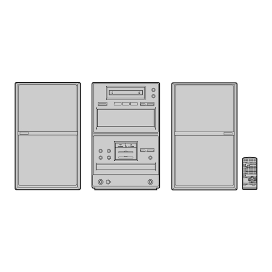
Page 4: Names Of Parts
MD-X5H/CP-X5H NAMES OF PARTS MD-X5H Display window 1. Level meter/Character Information Display 2. EON Indicator: EON 3. Disc Name Indicator: DISC 4. Programme Type Indicator: PTY 1 2 3 4 5 678 9 10 1112 5. Traffic Information Indicator: TI 6. - Page 5 MD-X5H/CP-X5H MD-X5H Rear Panel ANTENNA LOOP 1. AM Loop Aerial Input Socket 75 OHMS 2. FM 75 ohms Aerial Socket 3. Phono Input Sockets PHONO 4. Auxiliary Analog Input Jacks RIGHT LEFT 5. Auxiliary Analog Output Jacks AUX ANALOG IN/OUT 6.
-
Page 6: Operation Manual
MD-X5H/CP-X5H OPERATION MANUAL – 6 –... - Page 7 MD-X5H/CP-X5H – 7 –...
-
Page 8: Disassembly
MD-X5H/CP-X5H DISASSEMBLY MD-X5H Caution on Disassembly (A1)x1 Whe disassembling the machine or assenbling it after ø3x10mm repair, observe the following instructions so as to ensure safety and keep its performance. 1. Unload the compact disc, and mini-disc from machine. Top Cabinet (B1)x1 2. - Page 9 MD-X5H/CP-X5H Shield Case (Top Sode) Front Panel (P1) x 1 ø2 x 4mm (K1)x10 ø2.6x10mm (P1) x 1 Display PWB ø2 x 4mm (H1)x4 ø3x10mm (H3)x1 MDMecha Unit (H2)x1 (P1) x 1 ø2 x 4mm CD Holder (J1)x2 ø3x6mm Shield Case...
- Page 10 MD-X5H/CP-X5H MD Mechanism Push the vicinity of end of center decoration notch. Insert the head of screwdriver near , push further the screwdriver, pulling up the net. Thereby the lower pawl is disengaged (at first disengage at one side and then at other side).
-
Page 11: Removing And Reinstalling The Main Parts
MD-X5H/CP-X5H REMOVING AND REINSTALLING THE MAIN PARTS (A1)x1 MD MECHANISM SECTION ø1.7x5mm Perform steps 1 to 3 of the disassembly method to remove the MD mechanism. How to remove the magnetic head Magnetic Head (See Fig. 11-1) 1. Remove the screws (A1) x 1 pc. - Page 12 MD-X5H/CP-X5H How to remove the sled motor/loading motor (See Fig. 12-1) 1. Remove the screws (D1) x 1 pcs., and remove the sled (D1)x2 (D1)x2 motor/loading motor. Ø1.7x2mm Ø1.7x2mm Caution: Be careful so that the gear is not damaged. (The damaged gear emits noise during searching.)
-
Page 13: Cd Mechanism Section
MD-X5H/CP-X5H CD MECHANISM SECTION Perform steps 1,to 7 and 12 of the disassembly method to ( A1 ) x2 remove the CD mechanism. 2.6 x 6 mm How to remove the pickup (See Fig. 13-1) Optical Pickup 1. Remove the screw (A1) x 2 pcs., to remove the shaft (A2) x 1 pc. -
Page 14: Adjustment
MD-X5H/CP-X5H ADJUSTMENT TUNER SECTION • Setting the Test Mode Holding down the PRE-EQ button and TUNER(BAND) button, fL: Low-range frequency press the POWER button. Frequency is set in the memory as fH: High-renge frequency shown in Table 19. Call it with the PRESET button for tuner •... -
Page 15: Cd Test Mode
MD-X5H/CP-X5H CD TEST MODE CD test mode setting Any TEST mode can be set as shown below by pressing several buttons. Holding down TACK UP/CUE and CD PLAY/PAUSE, turn on POWER. Test Mode Function - CD TEST mode Test mode setting Initialization is not executed. - Page 16 Station name you assigned. Station name: (Preset station) Descriptions of the PTY (Programme Type) codes, TP (Traffic Programme) and TA (Traffic Announcement) With the MD-X5H, you can search for and receive the following PTY, TP and TA signals. News: News Pop M:...
- Page 17 MD-X5H/CP-X5H – 17 –...
- Page 18 TN—ON station. Preset memory takes priority of switching TN—ON station. therefore ASPM is usefull not only for PTY search but also for rapid EON switching. Anyway MD-X5H’s EON is basically stand-by and receiving method, along with the Guidelines for EON implementation.
- Page 19 MD-X5H/CP-X5H EON summary notice for reference 1. EON-TI/PTY EON stand-by can be set, only when EON ind. lights up. While EON ind. goes out (NO EON STATION), EON stand-by can't be set. If the EON button is pressed, then “NO EON” is indication the display.
- Page 20 MD-X5H/CP-X5H MD SECTION • Note Remove the MD unit for repeir, and after installing it in the set, be dure to reset it and ascertain that reset has been done. Resetting procedure (1) Unplug the AC cord from the socket, and hold down the RESET buttonm provided at the rear side for more than 10 seconds.
- Page 21 MD-X5H/CP-X5H • Test Mode 1. AUTO pre-adjustment mode • Automatic pre-adjustment is performed. (After adjustment the grating adjustment mode is set.) • The adjustment value is output with the aid of system controller interface. 2. AUTO adjustment mode • Automatic adjustment is performed.
- Page 22 MD-X5H/CP-X5H 2. AUTO adjustment mode Step No. Setting Method Remarks Display Step 1 Testmode STOP state [ t s m Step 2 Press the CD PLAY button two times. AUTO adjustment menu [ A U T O _ A J S T _ ] Step 3 Press once the MD PLAY button.
- Page 23 MD-X5H/CP-X5H 3. RESULT mode (final adjustment) Step No. Setting Method Remarks Display Step 1 Testmode STOP state [ t s m Step 2 Press the CD PLAY button four times. RESULT menu [ _ R E S U L T _ _ _ ] Step 3 Press once the MD PLAY button.
- Page 24 MD-X5H/CP-X5H • If the VOL UP/VOL DOWN button is pressed during setting indication, the setting increases/decreases, and the new setting is stored in RAM. • If the VOL UP/VOL DOWN button is held down, the setting changes continuously with 100 ms cycle.
- Page 25 MD-X5H/CP-X5H Setting Method Step No. Remarks Display Step 9 Press once the CD PLAY button. Comparison level setting in case of FOK generation [ F O K L E V f _ (when focus is "ON") Step 10 Press once the CD PLAY button. LPF coefficient setting (normal) in case of FOK generation...
- Page 26 MD-X5H/CP-X5H Setting Method Step No. Remarks Display Step 18 Press once the CD PLAY button. TCRS comparison level 1 for high reflection [ T C R S C 1 P _ Step 19 Press once the CD PLAY button. Comparison level in case of COUT generation (playback)
- Page 27 MD-X5H/CP-X5H e) TEMP setting Step No. Setting Method Remarks Display Step 1 Testmode STOP state [ t s m Step 2 Press the CD PLAY button seven times. EEPROM setting menu [E E P R O M _ S E T] Step 3 Press once the MD PLAY button.
- Page 28 MD-X5H/CP-X5H 8. TEST-PLAY mode Step No. Setting Method Remarks Display Step 1 Testmode STOP state [ t s m Step 2 Press the CD MD EDIT button. TEST-PLAY menu [ T E S T _ P L A Y _ ] Step 3 Press once the CD STOP button.
- Page 29 MD-X5H/CP-X5H 10. INNER mode Step No. Setting Method Remarks Display Step 1 Testmode STOP state [ t s m Step 2 Press the TRACK EDIT button. INNER menu [ _ _ I N N E R _ _ ] Step 3 Press once the MD PLAY button.
- Page 30 MD-X5H/CP-X5H Mechanism Adjustment 1. Optical pickup grating inspecting method OSILLOSCOPE 42 pin of IC 1101 GND (TP1131) 100K 26 pin of IC 1101 EOUT (TP1133) 470p GND CH1 CH2 470p Spindle Motor 25 pin of IC 1101 100K FOUT (TP1132)
-
Page 31: Explanation Of Error Display
MD-X5H/CP-X5H EXPLANATION OF ERROR DISPLAY Error display Errors Corrective action Can't REC • Defect occurred successively 10 times during REC-PLAY. • Check that the disc is free from flaw, dust • As a result of occurrence of defect during REC-PLAY the and fingerprint. - Page 32 MD-X5H/CP-X5H Error display Errors Corrective action BLANK MD • UTOC was read but total TNO and the number of characters of • Perform recording to check that the disc NAME was 0? is recordable disc. DEFECT • Focusing error was caused by shock during REC-PLAY.
- Page 33 MD-X5H/CP-X5H -PROM Data List Focus setting Slide setting Setting Item indication Setting Item indication S L G S L 2 F F 1 S L D L I M F F 2 S L D L E V F Z H L E V...
- Page 34 MD-X5H/CP-X5H -PROM Setting Mode Chart Figure 34 – 34 –...
-
Page 35: Notes On Schematic Diagram
MD-X5H/CP-X5H NOTES ON SCHEMATIC DIAGRAM Resistor: The indicated voltage in each section is the one measured by Digital To differentiate the units of resistors, such symbol as K and M are Multimeter between such a section and the chassis with no signal used: the symbol K means 1000 ohm and the symbol M means 1000 given. -
Page 36: Block Diagram
MD-X5H/CP-X5H Figure 36 BLOCK DIAGRAM (1/4) – 36 –... - Page 37 MD-X5H/CP-X5H XVDD CONT5 RVDD CONT4 LVDD VVDD XOUT SL– Figure 37 BLOCK DIAGRAM (2/4) – 37 –...
- Page 38 MD-X5H/CP-X5H CF352 MONO/ST MONO/ST STEREO T351 4.332MHz XT52 CF302 VDDD VSSD VDDA VSSA OSC. Figure 38 BLOCK DIAGRAM (3/4) – 38 –...
- Page 39 MD-X5H/CP-X5H UNA651 DIGITAL 1 OPTICAL JK652 SO801 JK603 SPEAKER DIGITAL2 HEADPHONES COAXIAL – – AC POWER SUPPLY CORD AC230V 50Hz IC554 NJM4558MF T801 OPE AMP. FAN MOTOR M800 POWER TRANSFORMER OM–OFF FAN MOTOR Q895 IC652 74HCU04 Q801 INVERTER F802 F803 T2.5A...
-
Page 40: Schematic Diagram/Wiring Side Of P.w.board
MD-X5H/CP-X5H C342 C343 0.022 R358 AM ANT. 8.2K VR351 T302 10K(B) L353 FM MUTE R319 10K LEVEL C330 C359 6.8P 150P (UJ) 20 19 FM I D301 1SS133 /FM MP D302 1SS133 CF302 CNP301 CF352 L341 AM LOOP AM IF... - Page 41 MD-X5H/CP-X5H RT34 QT21 KTC3199GR CT37 0.022 RT33 56K RT32 R364 3.9K RT55 LT22 R363 2.2 H C371 R361 3.9K CT28 1/50 TP TP MUTING 47/10 L354 RT26 Q353 CT29 0.022 LOW PASS KTC3199GR CT27 FILTER 24 23 22 21 R365...
- Page 42 MD-X5H/CP-X5H TO CD SERVO PWB CNP904 TO TUNER SECTION P51 10 - H TO TUN P40 10 - H CNS904 28 26 27 1 2 3 4 5 6 7 8 9 10 11 12 J737 R692 0.23 H A_10V...
- Page 43 MD-X5H/CP-X5H TO TUNER SECTION P41 10 - D 25 24 23 22 AUX_L_OUT AUX_GND R692 R429 AUX_R_OUT 2.2K Q423 LINE_L_IN KTC3199GR LINE_GND R431 R427 0.7V TUN_LCH R693 100K 5.6K LINE_R_IN 6.8K TUN_GND J_PHONO_L_IN TUN_RCH R432 R428 0.7V J_A_–12V 100K 5.6K...
- Page 44 MD-X5H/CP-X5H Q822 KRC107M R828 POWER AMP. D821 Q821 H:ON 1SS133 IC801 KRC107M L:OFF LA4451 17.5V Q501 C825 C831 R823 C827 DTC363TS 100/50 47/50 0.001 D822 – 1SS133 C823 1/50 R825 R827 H:ON R821 L:OFF P_L_IN C829 330/ 35 P_A_GND_IN R822...
- Page 45 MD-X5H/CP-X5H POWER AMP PWB-B3 ER AMP. C801 4451 C831 47/50 – C833 R829 1000/25 (1/2W) C837 C838 L801 L802 0.29 H (ML) 0.29 H (ML) R830 R839 FR834 FR833 (1/2W) (1/4W) (1/4W) R835 Fusible Fusible C832 C834 – 47/50 1000/25...
- Page 46 MD-X5H/CP-X5H 94 93 92 91 90 89 88 87 86 85 84 83 82 81 80 79 78 77 76 75 74 73 72 71 70 69 68 67 66 65 64 63 62 61 60 59 58 57 56 55 54 53 52 51 50 49 48...
- Page 47 MD-X5H/CP-X5H TO POWER AMP. PWB -35V CNP801 AC3.30V P44 1 - G CNS801 C744 C745 C746 1/50 1/50 1/50 C743 1/50 49 48 SW731 SW712 POWER R701 R711 R731 PLAY/PAUSE 1.2K 1.2K 1.2K R712 R732 SW713 1.5K 1.5K SW733 TRACK...
- Page 48 MD-X5H/CP-X5H LASER DRIVER 47/10 KTA1266GR 0.47/50 1.5V 4.9V 0.33/50 1/50 4.2V 0.01 4.7K 2.5V 0.2V FIN2 2.5V FIN1 2.5V EFBAL 2.5V 2.5V FOSTA DGND TOSTA 2.5V 2.5V 2FREQ 0.1/50 2.6V LASER 0.033 2.5V FSTA 100K LA9241M 8/12CM 2.6V SERVO AMP.
- Page 49 MD-X5H/CP-X5H R77 1K R46 1K R47 1K R45 1K R78 1K R48 1K 0.01 100P SERVO/SIGNAL CONTROL LC78623D 2.4V 2.5V 4.8V 4.7V 4.7V 2.4V 2.4V 0V 0V 2.2V EFLG 12P(CH) SBSY -COM SUB-CODE INTERFACE DEF1 XVSS 16.934MHz 15P(CH) 2.1V 3.3M...
- Page 50 MD-X5H/CP-X5H CD SERVO PWB-C (2/2) MD PLAYBACK SIGNAL MD RECORD SIGNAL C920 C919 100P 100P C913 R913 100P 5.6K OPEN_SW CLOSE_SW R914 5.6K R998 C-SW1 LOAD 0.2V 4.8V R1000 S-ID C-SW2 0.2V PU_IN R1002 C-SW3 RESET 0.2V SL– C-SW4 KR C107M 0.2V...
- Page 51 MD-X5H/CP-X5H 4.7V 4.7V DIG_IN_COAX R1044 0.2V DIG_GND 0.2V TO MAIN PWB DIG_GND CNP906 DIG_IN_OPT 4.3V P52 1 - G C936 DIG_+5V 4.8V 2.4V C937 P49 12 - D 1/50 2.4V TO CD SERVO SECTION DIG_IN_A BI936B IC904 C933 TO MD MAIN PWB 74HC153F 0.022...
- Page 52 MD-X5H/CP-X5H MAIN PWB-A1 (3/3) D651 1SS133 JK650 D652 R651 L651 1SS133 2.2mmH J_AUX_L_OUT L-CH C651 J_AUX_GND TO MAIN SECTION 330P AUX OUT J_AUX_R_OUT P43 12 - B C652 L653 330P 2.2mmH R-CH L655 R655 L652 R652 2.2mmH 2.2mmH L-CH R653 C653 3.9K...
- Page 53 MD-X5H/CP-X5H JACK PWB - A2 FM SIGNAL D_GND SO601 P50 1 - F KB_+5V KEY BOARD CNP907 KB_CLK_IN/OUT KB_DATA_IN/OUT TO CD SERVO PWB D631 D632 ISS133 ISS133 C634 0.022 INPUT LEVEL VR602 J_AUX_IN-R P43 12 - C J_AUX_IN-L CNP401 J_AUX_VOL-R...
- Page 54 MD-X5H/CP-X5H TP1141 C1117 3300P TP1131 C1107 C1110 TP1275 0.0047 0.47 TP1142 C1118 C1106 0.47 0.033 99 98 97 96 95 9 EFMAGI EFMAGC ADIPI C1119 TP1274 TP1140 EFMMON 330P R1155 AVCC ADIPO EFMO-I EFMO-I C1202 TP1139 EFMI 99 98 &...
- Page 55 MD-X5H/CP-X5H MD MAIN PWB-D R1211 C1208 0.047 P1275 TP1210 99 98 97 96 95 94 93 92 91 90 89 88 87 86 85 84 83 82 81 80 79 78 77 76 TP1216 EFMMON FEMON DADATA DADATA AVCC RC120...
- Page 56 MD-X5H/CP-X5H CNW401 RT54 CT28 RT53 CT37 RT51 Q354 RT34 RT52 CT27 C372 CT22 CT25 CT29 R362 CT26 CT24 RT48 CT21 QT21 RT21 R365 RT49 CT43 LT21 CT23 R364 Q353 C357 R393 ZDT21 R363 C358 R368 D353 R354 R367 TO CD SERVO PWB...
- Page 57 MD-X5H/CP-X5H C359 CNW401 L354 Q354 R350 C331 C372 T302 C367 R362 D302 D304 C353 C366 R399 R365 C341 IC303 CF302 R349 R348 C334 R347 L342 R364 Q301 Q353 C399 C351 C357 CF301 C348 L341 R393 B C E C346 R355...
- Page 58 MD-X5H/CP-X5H TO MAIN PWB P56 2 - C TO MAIN PWB CNS820B P56 2 - D CNS810 CNK820A POWER AMP PWB - B3 FAN MOTOR R895 M800 CNP810 K820A C876 C555 D822 R896 R863 C866 ZD880 D821 C875 CNP870 C872...
-
Page 59: Power Supply
MD-X5H/CP-X5H SW736 MD-EJECT DISPLAY PWB - B2 R735 SW735 R707 MD-REC R708 R732 R733 R734 R731 R736 SW731 POWER SW734 SW733 SW732 SW709 SW708 CD-MD EDIT TRACK MD-MD EDIT MD-PLAY/ MD-STOP PAUSE FL711 C743 R743 C706 RX701 60 55 IC712... - Page 60 MD-X5H/CP-X5H CD SERVO PWB-C (TOP) C916 R954 R923 C915 C912 C908 R929 R939 CNW93 R950 R1037 R952 R955 R961 R957 R964 R1034 R1039 R962 IC901 R934 R976 R984 R1036 R982 R979 R978 55 60 65 70 R991 R983 R981 R995...
- Page 61 MD-X5H/CP-X5H P59 7 - D TO DISPLAY PWB P64 2 - C TO PICKUP UNIT FW902 P56 6 - F TO JACK PWB CNS1 CNS907 7 6 5 4 3 2 1 CD SERVO PWB-C (BOTTOM) D904 1 2 3 4 5 6 7 8...
- Page 62 MD-X5H/CP-X5H P61 8 - G TO CD SERVO PWB CNP901 MD FLEXIBLE PWB (42) MD MAIN PWB - D (TOP) CNP 1902 CNP1252 TO MAGNETIC HEAD Q1820 C1251 CNS1252 C1252 P64 5 - H R1251 R1827 R1459 R1939 R1463 Q1253...
- Page 63 MD-X5H/CP-X5H P61 9 - F TO CD SERVO PWB CNP908 CNS1904A MD MAIN PWB - D (BOTTOM) JC121 R1947 TP1516 TP1519 TP1522 TP1518 TP1504 TP1520 TP1908 TP1502 TP1517 TP1252 TP1512 TP1501 TP1503 TP1907 R1805 TP1523 Q1807 TP1521 TP1905 Q1801 TP1801...
- Page 64 MD-X5H/CP-X5H CD MOTOR PWB-E PICKUP UNIT TO CD SERVO PWB PICKUP IN CNS3 M702 P61 12 - C SLED COLOR TABLE M701 SPINDLE BROWN R D ( R ) CNS1 CNS2 ORANGE TO CD SERVO PWB TO CD SERVO PWB...
-
Page 65: Voltage
MD-X5H/CP-X5H VOLTAGE (MD MAIN PWB) IC1601 IC1916 Q1801 IC1907 IC1201 IC1401 VOLTAGE NO. VOLTAGE NO. VOLTAGE NO. VOLTAGE NO. VOLTAGE NO. VOLTAGE VOLTAGE 1.58V 1.25V 2.8V 1.48V 3.2V 2.6V 1.5V 1.58V 4.9V 1.6V 0.2V 5.5V 3.2V 2.6V 3.2V 5.5V DIC input:2.2V 1.6V... -
Page 66: Waveforms Of Cd Circuit (Cd Section)
MD-X5H/CP-X5H WAVEFORMS OF CD CIRCUIT (CD SECTION) STOP PLAY FOCUS SERCH 0.5ms 0.50 V 10.0 V IC1 20 F.E 0.5ms 10.0 V 0.5ms 5.0 V 0.50 V IC1 54 DRF 0.5ms 1.00 V 0.5ms NORMAL DISC 1.00 V TN0=01 20ms PLAY 1.00 V... -
Page 67: Waveforms Of Cd Circuit (Md Section)
MD-X5H/CP-X5H WAVEFORMS OF MD CIRCUIT (MD SECTION) PLAY STATE PIT PLAY Stopped Stopped NORM: 100M S/s 1997 / 08 / 04 09:30:15 NORM: 1M S/s 1997 / 08 / 04 13:35:24 CH1 500mV 500ns/div 200mV 1ms/div AC 10:1 DC 10:1... - Page 68 MD-X5H/CP-X5H PLAY Stopped Stopped NORM: 1k S/s NORM: 100M S/s 1997 / 08 / 04 14:19:52 1997 / 08 / 04 11:23:12 2us/div 1s/div DC 10:1 DC 10:1 DC 10:1 DC 10:1 DC 10:1 DC 10:1 DC 10:1 Filter Filter...
-
Page 69: Troubleshooting (Cd Section)
MD-X5H/CP-X5H TROUBLESHOOTING (CD SECTION) When the CD does not function When the CD section does not operate When the objective lens of the optical pickup is dirty,this section may not operate.Clean the objective lens,and check the playback operation.When this section does not operate even after the above step is taken,check the following items. - Page 70 MD-X5H/CP-X5H • The CD operation button operates. Check the FOCUS-HF system. Playback is enabled without disc. Focus search OK Does the pickup move up and down two times? Check the IC5 to CNP2 and periphery. Is the output waveform of IC1 pin 16 (FD) identical with that shown in Figure 70-1? 0.5s...
- Page 71 MD-X5H/CP-X5H • Check the tracking system. Check the waveform of IC1 pin 7 (TE). Check the periphery from the IC1 pin 8 The waveform shown in Figure 71 appears. The tracking servo does not The discless state appears soon. to pin 15, from IC5 to CNP2.
- Page 72 MD-X5H/CP-X5H • Check the VCO-PLL system. Playback operation is performed when disc exists. Although the HF waveform is normal, the TOC data cannot Check the PDD waveform. (Figure 72) be read. Abnormal Check the IC1 pin 43, pin 44, IC2 pin 3, pin 5, pin 7, pin 10, and pin 11.
-
Page 73: Troubleshooting (Md Section)
MD-X5H/CP-X5H TROUBLE SHOOTING (MD SECTION) When MD fails to operate If the objective lens of optical pickup is contaminated, MD may fail to operate. At first, clean the objective lens to check playback operation. If MD fails persistently to operate, perform checks as follows. - Page 74 MD-X5H/CP-X5H • Disc loading is not normal. Is disc loaded when it is inserted? Check CNP1601 and SW1956. Is the pin 4 of CNP1601 set to L state? Is change observed on the pin 23 or 24 of IC1601? Check IC1401.
- Page 75 MD-X5H/CP-X5H • Normal playback When it has been confirmed that EEPROM value is normal in the TEST mode Is initialization performed normally when high reflection disc is Does the playback time display advance? played back? Check IC1201 Does disc rotate normally?
- Page 76 MD-X5H/CP-X5H • Record and playback operation Insert the low reflection disc, and after verifying the audio output in the normal mode playback set the record/playback TEST mode Recording from start address cannot be performed. Check whether the disc is record-prohibited.
- Page 77 MD-X5H/CP-X5H • Disc motor fails to run Check soldering joint and parts of pins 24 and 25 of IC1201, and Does waveform appear on the pins 24 and 25 of IC1201 in the peripheral circuit. TEST mode focus gain coarse adjustment step?
-
Page 78: Function Table Of Ic
MD-X5H/CP-X5H FUNCTION TABLE OF IC IC901 RH-iX2718AFZZ:System Control Microcomputer(iX2718AF) (1/2) Port Name Input/Output Pin No. Terminal Name Function 1*-4* C-SW1-C-SW4 P120/RTP0-P123/RTP3 In/Output Real time output port to output data synchronizing with trigger 5*-8* TRY_SW1-TRY_SW4 P124/RTP4-P127/RTP7 In/Output Real time output port to output data synchronizing with trigger —... - Page 79 MD-X5H/CP-X5H IC901 RH-iX2718AFZZ:System Control Microcomputer(iX2718AF) (2/2) Terminal Name Port Name Input/Output Function Pin No. JOG_B P46/AD6 In/Output Low-order address/data bus in case of external memory expansion JOG_A P47/AD7 In/Output Low-order address/data bus in case of external memory expansion CCB-CE P50/A8...
- Page 80 MD-X5H/CP-X5H IC712 RH-iX0069AWZZ:FL Driver (IX0069AW) Pin No. Terminal Name Function 1-12 DIG11-DIG00 Digit output RESET Reset input Chip selection input Shift clock input SDATA Serial data input 17*,18* P1,P0 Output port (static operation) Vcc1 Positive power terminal for internal logic...
- Page 81 MD-X5H/CP-X5H IC1101 VHiiR3R55//-1:RF Signal Control (IR3R55) Function Terminal Name Pin No. RF signal input terminal 1 Input of RF signal output of pickup RF signal input terminal 2 Input of RF signal output of pickup RF signal input terminal 3 Input of RF signal output of pickup...
- Page 82 MD-X5H/CP-X5H IC1201 VHiLR37648/-1:ENDEC/ATRAC (LR37648) (1/2) Function Terminal Name Input/Output Pin No. EFMMON Output EFM monitor output AVCC — Analog power EFMI Input EFM signal input from RF amp. AGND — Analog GND Input Focus error signal A Input Tracking error signal E...
- Page 83 MD-X5H/CP-X5H IC1201 VHiLR37648/-1:ENDEC/ATRAC (LR37648) (2/2) Function Terminal Name Input/Output Pin No. TESO1 Output PLLLR. Microcomputer extension output port 2 in case of selection TESO3 In/Output PLLOSC. Microcomputer extension output port 3 in case of selection TEST4 In/Output EXTCLK. Microcomputer extension output port 4 in case of selection...
- Page 84 MD-X5H/CP-X5H IC1401 RX-iX0227AWZZ:MD System Microcomputer (IX0227AW) (1/2) Function Terminal Name Input/Output Pin No. P96/ANEX1 Output Input/Output it port P96 P95/ANEX0 Output Input/Output it port P96 P94/DA1 Output LDVAR (laser power adjustment output) P93/DA0 Output ADJS (for automatic adjustment step check)
- Page 85 MD-X5H/CP-X5H IC1401 RX-iX0227AWZZ:MD System Microcomputer (IX0227AW) (2/2) Function Terminal Name Input/Output Pin No. P42/A18 In/Output SYS D2 (data bus 2) P41/A17 In/Output SYS D1 (data bus 1) P40/A16 In/Output SYS D0 (data bus 0) P37/A15 Output Input/Output it port P37...
- Page 86 MD-X5H/CP-X5H IC1101 VHiiR3R55//-1: RF Signal Control (IR3R55) ADIPI ADIPO DIFF DIFF ADLPFO ADIP REFI 22KO REFO 22KI BIAS RFADD TCGI TCGO AOUT BOUT EOUT LOGIC FOUT Figure 86-1 BLOCK DIAGRAM OF IC IC1201 VHiLR37648/-1: ENDEC/ATRAC (LR37648) 75 74 73 72 71 70 69 68 67 66 65 64 63 62 61 60 59 58 57 56 55 54 53 52 51...
-
Page 87: Parts Guide
“HOW TO ORDER REPLACEMENT PARTS” To have your order filled promptly and correctly, please furnish the For U.S.A. only following information. Contact your nearest SHARP Parts Distributor to order. 1. MODEL NUMBER 2. REF. No. 3. PART NO. 4. DESCRIPTION For location of SHARP Parts Distributor, Please call Toll-Free;... - Page 88 MD-X5H/CP-X5H PRICE PRICE DESCRIPTION PART CODE PARTS CODE DESCRIPTION RANK RANK Q1401 VSRN2404///-1 AC Digital,PNP,RN2404 MD-X5H Q1402 VSRNC1404//-1 AB Digital,NPN,RNC1404 Q1403 VSRN2404///-1 AC Digital,PNP,RN2404 INTEGRATED CIRCUITS Q1404 VSRNC1404//-1 AB Digital,NPN,RNC1404 Q1451 VSRNC1407//-1 AC Digital,NPN,RNC1407 VHILA9241M/-1 AS Servo Amp.,LA9241M Q1601 VS2SA1314C/-1...
- Page 89 MD-X5H/CP-X5H PRICE PRICE DESCRIPTION PARTS CODE DESCRIPTION PART CODE RANK RANK L1102 VPBNNR47K0000 AC 0.47 H C301 VCKYMN1HB102K J AA 0.001 F,50V L1201 VPBNNR47K0000 AC 0.47 H C330 VCCUMN1HJ6R8D J AB 6.8 pF (UJ),50V L1203 VPBNN4R7K0000 AC 4.7 H C331 VCKZPA1HF473Z AA 0.047 F,50V...
- Page 90 MD-X5H/CP-X5H PRICE PRICE PART CODE DESCRIPTION PARTS CODE DESCRIPTION RANK RANK C625,626 VCKYPA1HF103Z AB 0.01 F,16V C899 RC-GZA335AF1H AB 3.3 F,50V,Electrolytic C628 VCKYPA1HF223Z AB 0.022 F,50V C901 VCKYPA1HF473Z AB 0.047 F,50V C634 VCTYMN1EF223Z AA 0.022 F,25V C908 VCCCTV1HH100D J AA 10 pF (CH),50V...
- Page 91 MD-X5H/CP-X5H PRICE PRICE PART CODE DESCRIPTION PARTS CODE DESCRIPTION RANK RANK C1807 VCEAPS227AF0G AC 220 F,4V,Electrolytic VRS-TV2AB273J AA 27 kohms,1/10W C1810 VCKYTV1CF105Z AB 1 F,16V VRS-TV2AB681J AA 680 ohms,1/10W C1904 VCKYTQ1CB334K AC 0.33 F,16V VRS-TV2AB102J AA 1 kohm,1/10W C1913 VCCCCY1HH220J...
- Page 92 MD-X5H/CP-X5H PRICE PRICE PART CODE DESCRIPTION PARTS CODE DESCRIPTION RANK RANK R555 VRD-ST2CD102J AA 1 kohm,1/6W R861 VRD-ST2CD222J AA 2.2 kohms,1/6W R556 VRD-MN2BD102J AA 1 kohm,1/8W R862 VRD-ST2EE221J AA 220 ohms,1/4W R557,558 VRD-MN2BD272J AA 2.7 kohms,1/8W R863 VRD-ST2CD472J AA 4.7 kohms,1/6W...
- Page 93 MD-X5H/CP-X5H PRICE PRICE PART CODE DESCRIPTION PARTS CODE DESCRIPTION RANK RANK R1261~1263 VRS-CY1JB103J AA 10 kohm,1/16W R1810 VRS-CY1JB102J AA 1 kohm,1/16W R1266 VRS-CY1JB103J AA 10 kohm,1/16W R1811 VRS-CY1JB273J AA 27 kohms,1/16W R1281 VRS-CY1JB470J AA 47 ohms,1/16W R1820,1821 VRS-TV2AB1R0J AA 1 ohm,1/10W...
- Page 94 MD-X5H/CP-X5H PRICE PRICE DESCRIPTION PART CODE PARTS CODE DESCRIPTION RANK RANK F805,806 92LFUSET631E AC Fuse,T630mA L 250V NGERH0066AWZZ J AC Gear,Loading (B) FE301 RTUNS0007AWZZ J AT FM Front End NGERH0067AWZZ J AC Gear,Drive FL711 VVK16ST15G/-1 BH FL Display NGERH0068AWZZ J...
- Page 95 MD-X5H/CP-X5H PRICE PRICE PART CODE DESCRIPTION PARTS CODE DESCRIPTION RANK RANK JKNBZ0419AWSA AF Button,Volume Down SPAKP0050AWZZ AC Polyethylene Bag,Operation JKNBZ0420AWSA AE Button,X-BASS Manual PSHEP0018AWSA J AH Sheet,FL Display 92LF-ANT1535A AF FM Antenna HDECQ0279AWSA J AG Panel,FL Display RRMCG0111AWSA J BB Remote Control...
- Page 96 MD-X5H/CP-X5H MD-X5H 306-2 306-1 306-3 M701 M702 305x2 SW702 PWB-E Figure 9 CD MECHANISM EXPLODED VIEW – 9 – – 96 –...
- Page 97 MD-X5H/CP-X5H MD-X5H CNS1903 SW1956 PWB-F SW1953 1952 SW1954 SW1955 603x2 CFW1901 603x2 PWB-A 612x4 M902 M903 M901 606x3 Figure 10 MD MECHANISM EXPLODED VIEW – 10 – – 97 –...
- Page 98 MD-X5H/CP-X5H MD-X5H 601x3 M800 601x4 601x2 Mechanism 601x3 605x7 610x2 610x10 610x2 PWB-B2 213 214 606x2 610x2 615x3 610x3 602x2 602x2 221x2 613x2 PWB-C PWB-A2 SW701 618x2 605x2 Mechanism M703 611x2 PWB-B1 616x2 611x3 607x4 604x3 Silicon Grease PWB-B3 249x4...
- Page 99 MD-X5H/CP-X5H CP-X5H TWEETER SP3, 4 C1, 2 WOOFER SP1, 2 709x6 709x2 SP3, 4 SP1, 2 709x4 708 / 711 Figure 12 SPEAKER EXPLODED VIEW – 99 – – 12 –...
- Page 100 MD-X5H/CP-X5H PACKING OF METHOD (FOR UK ONLY) MD-X5H CP-X5H 1. Packing Case SPAKC0576AWZZ 1. Packing Add., Top/Bottom, Speaker 92L412-0089 2. Packing Add., Left/Right SPAKA0149AWZZ 2. Polyethylene Bag, Speaker 92L411-0089 3. Polyethylene Bag, Unit SSAKH0024AWZZ 3. Sheet 92L414-0017 4. Polyethylene Bag, Accessories 92LBAG1460C1 4.
- Page 101 MD-X5H/CP-X5H — M E M O — – 101 – – 14 –...
- Page 102 MD-X5H/CP-X5H — M E M O — – 102 – – 15 –...
- Page 103 MD-X5H/CP-X5H — M E M O — – 103 – – 16 –...
- Page 104 MD-X5H/CP-X5H © COPYRIGHT 1997 BY SHARP COPORATION ALL RIGHTS RESERVED. No part of this publication may be reproduced, stored in a retrieval system, or transmitted in any from or by any means, electronic, mechanical, photocopying, recording, or otherwise, without prior written permission of the publisher.
Need help?
Do you have a question about the MD-X5H and is the answer not in the manual?
Questions and answers