
Subscribe to Our Youtube Channel
Related Manuals for Grizzly Foot Shear T20797


Summary of Contents for Grizzly Foot Shear T20797
- Page 1 MODEL T20797 52" FOOT SHEAR OWNER'S MANUAL WARNING: NO PORTION OF THIS MANUAL MAY BE REPRODUCED IN ANY SHAPE OR FORM WITHOUT THE WRITTEN APPROVAL OF GRIZZLY INDUSTRIAL, INC.
-
Page 3: Table Of Contents
Table of Contents INTRODUCTION ... 2 SECTION 1: SAFETY ... 5 SECTION 2: SET UP ... 8 SECTION 3: OPERATIONS ... 14 SECTION 4: ACCESSORIES ... 18 SECTION 5: MAINTENANCE... 20 SECTION 6: SERVICE ... 21 SECTION 7: PARTS ... 24 WARRANTY AND RETURNS ... -
Page 4: Introduction
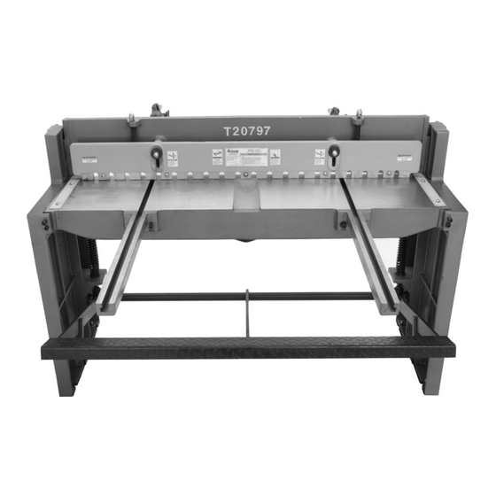
INTRODUCTION Manual Accuracy Functional Overview your machine may not exactly match the manual www.grizzly.com Contact Info... - Page 5 Identification Figure 1.
-
Page 6: Machine Data Sheet
Machine Data Sheet MACHINE DATA SHEET MODEL T20797 52" SHEET METAL SHEAR Product Dimensions: Capacities: Construction: Features: Model G5772 Page 1 of 1... -
Page 7: Safety Instructions For Machinery
Safety Instructions for Machinery... -
Page 9: Additional Safety Instructions For Foot Shears
Additional Safety Instructions for Foot GUARDS. 2. FOOTING. 3. HANDS AND FINGERS. 4. OPERATOR POSITION. 5. CAPACITY. 6. PROPER USE. Like all machinery there is potential danger when operating this machine. Accidents are frequently caused by lack of familiarity or failure to pay attention. -
Page 10: Section 2: Set Up
SECTION 2: SET UP Setup Safety This machine presents serious injury hazards to untrained users. Read through this entire manu- al to become familiar with the controls and opera- tions before starting the machine! Wear safety glasses dur- ing the entire set up pro- cess! The Model T20797 is extremely... - Page 11 Inventory Box 1: (Figure 2) NOTICE Some hardware/fasteners on the inventory list may arrive pre-installed on the machine. Check these locations before assuming that any items from the inventory list are miss- ing. SUFFOCATION HAZARD! Immediately discard all plas- tic bags and packing materi- als to eliminate choking/suf- focation hazards for children and animals.
-
Page 12: Site Considerations
Clean Up Figure 3 For optimum performance, clean all moving parts or sliding contact surfaces. Gasoline and petroleum products have low flash points and can explode or cause fire if used to clean machinery. NOT use these products to clean the machinery. Many cleaning solvents toxic Minimize your risk by only... -
Page 13: Moving & Placement
Moving & Placement Mounting to Shop Floor Figure 5. Figure 6 NOTICE Anchor studs are stronger and more per- manent alternatives to lag shield anchors; however, they will stick out of the floor, Figure 5. Lifting the foot shear. which may cause a tripping hazard if you decide to move your machine. - Page 14 Assembly To assemble the foot shear: Figure 7. Figure 8. Figure 7 Figure 9. Foot pedal and front extension arms. Figure Figure 9...
- Page 15 To install the rear extension rods (optional): Figure 11 Figure 10 Figure 11. Figure 10.
-
Page 16: Section 3: Operations
WE STRONGLY RECOMMEND that you read books, trade magazines, or get formal training before beginning any projects. Regardless of the content in this section, Grizzly Industrial will not be held liable for accidents caused by lack of training. Basic Controls... -
Page 17: Stops & Guides
Stops & Guides Shearing Tips Figure 14 Figure 14. Operation Overview To use the foot shear: Figure 15. Finger Guard Step 1... -
Page 18: Blade Adjustment
Hold-Down Adjustment Items Needed To adjust the hold-down: Figure 16. Step 2 Tip: To avoid scratching the surface of your workpiece, apply thin rubber pads to the bottom of the hold-down fingers. Blade Adjustment Tools Required Qty. To perform the blade adjustment: Figure 16 NOTICE: The moving blade should never overlap the fixed blade. - Page 19 Adjusting Blade Bow Figure 18 Note: 0.002" is a good starting point for most operations. The gap width will change, however, depending on the type and gauge of the material being sheared. This is a trial- and-error process. Test with scrap pieces until you achieve satisfactory results.
-
Page 20: Section 4: Accessories
SECTION 4: ACCESSORIES G5618—Deburring Tool with two Blades G5619—Extra Aluminum Blades G5620—Extra Brass and Cast Iron Blade Figure 19. H3153—Pigskin Palm Gloves H3154—Lined Pigskin Palm Gloves H3153 Figure 20. H5614—Wire Gauge US Standard Figure 21. G5562—SLIPIT G5563—SLIPIT G2871—Boeshield G2870—Boeshield H3788—G96 H3789—G96 H3154 Figure 22. - Page 21 G4956—Super Nibbler Figure 23. H5958—Sheet Metal Pliers Figure 24. G8781—4 ⁄ " Suction Cup Figure 25. H6131—Heavy-Duty Hand Riveter Figure 26.
-
Page 22: Section 5: Maintenance
SECTION 5: MAINTENANCE Schedule Daily Check: Figure 28. Unpainted Cast Iron Lubrication Figure 27). Figure 29. Figure 28 Figure 29 Figure 30 Figure 30. Figure 27. -
Page 23: Section 6: Service
SECTION 6: SERVICE Troubleshooting Operations Page Page 22 Page 16 Page 16... -
Page 24: Adjusting Blade Bow
Adjusting Blade Bow Gib Adjustment Tools Required Qty. Tools Required Qty. Figure 32 Blade Adjustment Figure 33 Figure 33. Figure 31. Figure 32. -
Page 25: Blade Sharpening/Replacement
Blade Sharpening/ Replacement Tools Required Qty. Note After new blades are installed or old blades are sharpened, they must be adjusted. Figure 34 Figure 34. -
Page 26: Section 7: Parts
SECTION 7: PARTS Parts Breakdown... -
Page 27: Parts List
PART # DESCRIPTION PT20797001 TABLE PT20797002 CUTTER BAR PT20797003 HOLD DOWN PT20797004 RH SIDE PANEL PT20797005 LH SIDE PANEL PT20797006 FRONT ARM EXTENSION PSB131M CAP SCREW M12-1.75 X 45 PT20797008 COMPRESSION SPRING PT20797009 SPRING STUD M12-1.75 PN09M HEX NUT M12-1.75 PT20797011 STUD M12-1.75 X 80 PW06M... -
Page 28: Labels Breakdown & List
MUST maintain the original location and readability of the labels on the machine. If any label is removed or becomes unreadable, REPLACE that label before using the machine again. Contact Grizzly at (800) 523-4777 or www.grizzly.com to order new labels. Parts List... -
Page 31: Warranty And Returns
WARRANTY AND RETURNS...
Need help?
Do you have a question about the Foot Shear T20797 and is the answer not in the manual?
Questions and answers