Table of Contents
Advertisement
Quick Links
Advertisement
Table of Contents

Subscribe to Our Youtube Channel
Related Manuals for PROEL PLLEDMLBG


Summary of Contents for PROEL PLLEDMLBG
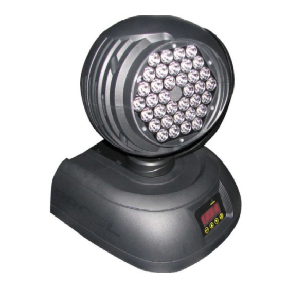
- Page 1 MANUALE UTENTE – USER’S MANUAL PLLEDMLBG LED MOVING HEAD Rev. 11/2006...
-
Page 2: Table Of Contents
INTRODUCTION................12 SPECIFICATION................12 SAFETY COMMAND ................. 13 ACCESSORIES INCLUDED .............. 13 FIXING INSTRUCTION ..............13 CONTROL TUNNEL ................17 APPENDIX 1: adapting system from 5 core to 3 core plug ....18 APPENDIX 2: function settings............18 APPENDIX 3: Setting Of All Functions..........19... -
Page 3: Introduction
INTRODUCTION Thank you for selecting our products named LED Move Head Light , In the sake of your safety and better use of this product, please read this user’s manual carefully and note the rules strictly before you use this product: It adopts advanced design and processing technics and has trim appearance. -
Page 4: Safety Command
SAFETY COMMAND 1 3 0 A v o i d C u rr e n t -P a s s in g H i g h Te m p e r a t u r e L a m p Repaired by regular maintenance only. - Page 5 LED Move Head Light use 6A / 250V fuse. RIGGING DANGER TO LIFE: Please consider the respective national norms during the installation. The installation must only be carried out by an authorized dealer. The installation must always be secured with a secondary safety attachment safety rope).
- Page 6 Omega Holders Aliscaf Screws Safety cable...
- Page 7 OPERATION INSTRUCTIONS The LED moving head uses LED digital display method to control the channel setting. The LED moving head adopts international standard DMX-512 signal, multiple lights can be controlled by the controller due to use the channel setting (the details are listed in Appendix 2 Use the XLR-XLR cable from the signal output port of the consol to connect the signal input port of the first light, connect the signal output port of the first light with the signal input port of the second...
-
Page 8: Control Tunnel
from 5 core to 3 core will be needed if the controller you use is 5 core outlet (plug). (Please refer to Appendix 1). When power is on, the equipment will undertake self-examination, and can undertake operation after the self-examination is finished. Please don’t shake the equipment when it is in operation. -
Page 9: Appendix 1: Adapting System From 5 Core To 3 Core Plug
APPENDIX 1: adapting system from 5 core to 3 core plug Û 3Core Plug Pin 1:G ND(SCREEN) Pin 1:G ND(SCREEN) Pin 2:Signal(+ ) Pin 2:Signal(+ ) Pin 3:Signal(-) Pin 3:Signal(-) Pin 1:G ND(SCREEN) Pin 1:G ND(SCREEN) Pin 2:Signal(+ ) Pin 2:Signal(+ ) Pin 3:Signal(-) Pin 3:Signal(-) Pin 4:N/C... -
Page 10: Appendix 3: Setting Of All Functions
CHSL is defined as Channels Switch which total are two option include ON & OFF. When it is in “ON” position, the CHSL light is maximum channels. When it shows “OFF”, the light is the last two channels. 16 Bit is useless. PERF is defined as light working speed adjustment with MAX and NOMA. - Page 11 PROEL S.p.A. (World Headquarters – Factory) Via alla Ruenia 37/43 64027 Sant’Omero (TE) – Italy Tel. +39 0861 81241 Fax. +39 0861 887862 e-mail: info@proelgroup.com www.proelgroup.com...
Need help?
Do you have a question about the PLLEDMLBG and is the answer not in the manual?
Questions and answers