Table of Contents
Advertisement
Available languages
Available languages
Quick Links
Advertisement
Table of Contents

Related Manuals for PROEL PLLED125


Summary of Contents for PROEL PLLED125
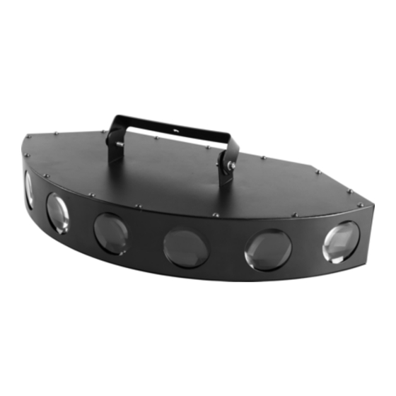
- Page 1 LED EFFECT PLLED125...
-
Page 2: Table Of Contents
INDICE NORME DI SICUREZZA....................3 ALIMENTAZIONE ......................4 MONTAGGIO IN SOSPENSIONE.................. 4 CONNESSIONE CON UNA LINEA DMX ..............5 MESSA IN FUNZIONE...................... 6 MANUTENZIONE......................9 DATI TECNICI........................9 TABLE OF CONTENTS MAIN GUIDELINES......................10 AC POWER........................11 OVEREAD MOUNTING ....................11 DMX 512 CONNECTION ....................12 OPERATION........................13 BASIC SERVICE ........................16 TECHNICAL DATA......................16... -
Page 3: Norme Di Sicurezza
Si prega di contattare un distributore PROEL per ricevere assistenza per qualsiasi dubbio su come attivare l’apparecchiatura in modo sicuro. Rivolgersi ad un tecnico qualificato per qualsiasi operazione di manutenzione non descritta nel presente manuale. -
Page 4: Alimentazione
IEC localizzata nella parte posteriore dell’apparecchiatura. MONTAGGIO IN SOSPENSIONE PLLED125 è progettato per essere montato sospeso con un gancio (non incluso). Attenzione! Bloccare l’accesso al di sotto dell’area di lavoro prima di procedere. Usare sempre un mezzo sicuro di aggancio secondario (fune di sicurezza). -
Page 5: Connessione Con Una Linea Dmx
CONNESSIONE CON UNA LINEA DMX Proiettore 3 Proiettore 2 Proiettore 1 Indirizzo 19 Indirizzo 10 Indirizzo 1 DMX-512 Controller I cavi DMX non devono venire a contatto con altri cavi, in tal caso infatti gli apparecchi potrebbero non funzionare correttamente o non funzionare affatto. Usare solo cavi DMX con spina e presa tipo XLR 3 poli, per la connessione alla centralina DMX o per il collegamento tra apparecchi. -
Page 6: Messa In Funzione
MESSA IN FUNZIONE Dopo aver connesso il proiettore alla rete di alimentazione, esso può essere acceso. Ogni proiettore occupa 9 canali DMX. Per fare in modo che il segnale di controllo sia correttamente ricevuto da ogni proiettore, è necessario che ognuno di essi sia indirizzato. Questo può essere fatto per ogni singolo proiettore cambiando le configurazioni dei dipswitch, come indicato di seguito. - Page 7 CANALI DMX Canale Funzione Valore Specifiche 000 – 007 Spento CH 1 Dimmer / strobo 008 – 231 Strobo da min a max 232 – 255 Acceso CH 2 Effetti strobo 000 – 255 000 – 016 Figura 1 017 – 033 Figura 2 034 –...
- Page 8 102 – 118 6 acceso 1 spento da destra a sinistra 119 – 135 6 acceso 1 spento da sinistra a destra 136 – 152 6 acceso 1 spento da destra a sinistra e viceversa 153 – 169 4 accesi 3 spenti da destra a sinistra e viceversa 170 –...
-
Page 9: Manutenzione
MANUTENZIONE Per mantenere elevata la qualità delle prestazioni di PLLED125, è fondamentale una pulizia regolare degli elementi dell’asse ottico, così come dei fori di aerazione e della ventola di raffreddamento. Importante! Polvere eccessiva, depositi di fumo ed altre scorie riducono le prestazioni e causano surriscaldamento. -
Page 10: Main Guidelines
If you have questions about how to operate the fixture safely, please contact a PROEL distributor for assistance. Refer any service operation not described in this manual to a qualified technician. -
Page 11: Ac Power
Connect the mains power cable to the fixture at the 3-prong IEC male input socket at the rear of the fixture. OVERHEAD MOUNTING PLLED125 is designed to be hung overhead with a clamp (not included). Warning! Block access below the work area before proceeding. Always use a secure means of secondary attachment (safety rope). -
Page 12: Dmx 512 Connection
DMX-512 CONNECTION Projector 3 Projector 2 Projector 1 Address 19 Address 10 Address 1 DMX-512 Controller The wires must not come into contact with each other, otherwise the fixtures will not work at all, or not will work properly. Only use only a DMX cable and 3-pin XLR-plugs and connectors in order to connect the controller with the fixture or one fixture with another. -
Page 13: Operation
OPERATION After you connected the effect to the mains, the fixture starts running. During the reset, the motors are trimmed and the device is ready for use afterwards. Each projector occupies 9 channels. To ensure that the control signals are properly directed to each projector, the projector requires addressing. - Page 14 DMX CONTROL CHANNELS Channel Function Value Specifications 000 – 007 CH 1 Dimmer / strobe 008 – 231 Strobe from min to max 232 – 255 CH 2 Strobe effects 000 – 255 000 – 016 Pattern 1 017 – 033 Pattern 2 034 –...
- Page 15 119 – 135 6 on 1 of from right to left 136 – 152 6 on 1 of from right to left, come and back movement 153 – 169 4 on 3 off come and back movement 170 – 186 2 on from left to right 187 –...
-
Page 16: Basic Service
BASIC SERVICE Regular cleaning of the elements in the optical path, as well as the air vents, is vital to maintaining the operational quality of the PLLED125. Important! Excessive dust, smoke fluid, and particulate build-up degrades performance and causes overheating and damage to the fixture that is not covered by the warranty.
Need help?
Do you have a question about the PLLED125 and is the answer not in the manual?
Questions and answers