Table of Contents
Advertisement
Quick Links
Advertisement
Table of Contents

Subscribe to Our Youtube Channel
Related Manuals for Cloud Z4II


Summary of Contents for Cloud Z4II
- Page 1 & Z8 ZONE MIXERS Installation and User Guide...
-
Page 3: Table Of Contents
Contents Safety Information ........4 Setting Up & Operation ....... 16 Safety Notes Regarding Installation ....4 Music Inputs ............16 Gain & level ............... 16 Conformities ............4 Local/remote control ............16 Safety Considerations and Information ..... 4 Microphone Inputs ..........16 Phantom Power ............... -
Page 4: Safety Information
Safety Information Safety Notes Regarding Safety Considerations and Installation Information • Do not expose the unit to water or moisture. The Z4 and Z8 must be earthed. Ensure that the mains power supply provides an effective earth connection using a •... -
Page 5: Overview
(if practical), in case features, flexibility and reliability. you ever need to return the unit to your Cloud dealer for any reason. The Cloud Z4... -
Page 6: Optional System Components
Optional System Components control of zone music level and source. The music ducking facility is also provided for the mic input. See page 12 (Connecting an LM-1 remote input plate) and page 18 (LM-1 The following components may form part of the audio and DM-1 active input plates) for more information. -
Page 7: Pm Series Paging Microphones
PM Series Paging Microphones PM1 Paging Microphone fig.5: PM16 fig.6: PM1 Cloud PM paging microphones may be connected directly to The Cloud PM1 paging microphone is also compatible with the Z8 and Z4 . Models are available which can page to 4, 8,... -
Page 8: Front Panel Description
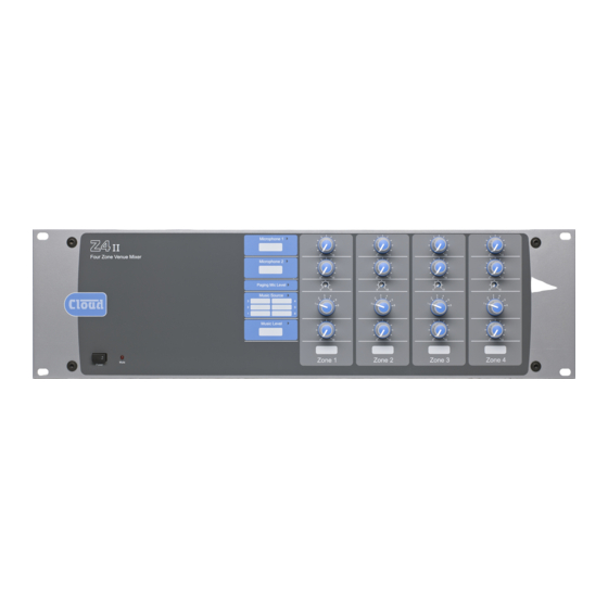
fig.8: Z8 Front Panel Note - The front panel of the Z8 is shown above. The Z4 ’s is identical, except that it only has controls for zones 1 - 4. Front Panel Description POWER – latching push-button switch with integral MUSIC SOURCE –... -
Page 9: Rear Panel Description
fig.9: Z8 Rear Panel Note - The rear panel of the Z8 is shown above. The Z4 ’s is identical, except that it only has output connections for zones 1 - 4. Rear Panel Description PAGING MIC ACCESS PORT – 10-pin 5 mm-pitch screw-terminal connector for per-zone contact closure LINE INPUTS –... -
Page 10: Installation
Installation Hardware Considerations System Connections The Z4 and Z8 Zone Mixers are built in 3U-high 19” rack Music Sources mount enclosures. It is recommended that the Zone Mixer Connect the system’s various music sources to LINE 1 is installed in a 19” rack wherever possible. The units are to LINE 6. -
Page 11: Zone Outputs
*ZONE 1 to 4 only on Z4 LEFT RIGHT LEFT Balanced outputs (XLRs): pin 1 ground pin 2 hot pin 3 cold Z8II/Z4II Balanced output: pin 1 ground pin 2 cold pin 3 hot RIGHT Balanced outputs (XLRs): pin 1 ground pin 2 hot... -
Page 12: Microphone Inputs
Microphone inputs Connecting a DM-1 remote input plate The DM-1 should be connected to a Facility Port using Mic 1 and Mic 2 inputs are intended for the direct multicore cable with an overall screen. 7 of the 9 pins are connection of microphones. -
Page 13: Paging System Connections
ZONE ACCESS PAGING MIC INPUT Source Select controls become inoperative. Z8II MIXER Paging System connections Cloud PM Series paging microphones may be connected fig.18: PM8 - Z8 wiring connections directly to the Z4 and Z8 For individual zone paging as described above, the paging Two connections are required: the paging mic audio signal mic priority trigger should be selected to ‘SW’... -
Page 14: Connecting A Pm1 Paging Mic
It can be connected directly to Z8 zone zone. The Cloud remote control plates models RL-1 (music mixers, the control cable being wired to the pin(s) of the level only) and RSL-6 (music level and source selection) -
Page 15: Connecting An Rsl-6 Remote Control Plate
Connecting an RSL-6 remote control plate Wire the remote control plate as shown below. Twin-and- screen cable should be used. Maximum reliable cable run is 100 m. MUSIC MUTE INPUT REMOTE SOURCE & LEVEL CONTROL WIRING REMOTE MUSIC CONTROL PORT RSL-6 NORMALLY OPEN (NO) CONNECTION... -
Page 16: Setting Up & Operation
The paging mic input also has 15 V phantom power available. REMOTE switch. If external control of music level only (i.e., This will NOT be required if a Cloud paging microphone is not source selection) is required, J1 should be set to FR and being used with the mixer, but may be necessary with other the LOCAL/REMOTE switch to REMOTE. -
Page 17: Gain & Level
signals will restore smoothly to their former level, over a Gain & level period of 3, 6 or 12 seconds. The paging mic input has a rear panel preset gain control The Mic 1/Mic 2 priority over music can be disabled on a on page 9). -
Page 18: Options And Additional Information
(in a large function room, for example). DM-1 dual microphone input plates may be “daisy- Cloud DM-1 and LM-1 remote input plates are the same chained” to achieve this. All DM-1s thus wired will, of course,... -
Page 19: Using The Facility Ports As Auxiliary Zone Inputs
DC voltage of between 0 and +10 V to pin 2, the 0 V reference being connected to Pin 1. 0 V on pin 2 Cloud RL-1 and RSL-6 remote input plates are the same corresponds to maximum level and +10 V will produce 60 physical size as a single-gang UK electrical socket and can be dB of attenuation. -
Page 20: Music Source
Music source Music source for a zone may be controlled by applying various DC voltages of between 0 and +10 V to pin 3, the 0 V reference being connected to pin 1. 0 V at pin 3 will select Line input 6 and between +7.5 and +9 V will select Line input 1. - Page 21 & Z8 Installation and User Manual v1.0...
-
Page 22: Appendix
• Area 3 has a Cloud PM paging microphone, which would be used to originate voice messages to any of the other areas. The paging level to Area 3 (if required) would be adjusted on installation to be at a level that does not cause feedback. -
Page 23: Pcb Jumper Location And Settings
PCB jumper location and settings The Z4 and Z8 have various internal jumpers, the setting of which may require alteration during installation. Note that there are jumpers on both the motherboard and the individual zone sub-cards. The table below lists each jumper and its purpose, together with the factory default setting. - Page 24 FRONT OF UNIT ZONE SUB-CARDS MOTHERBOARD (at bottom of chassis) POWER TRANSFORMER * Z8 ONLY KEY: Jumper with two possible positions; black square indicates factory default setting. fig.27: Jumper locations (COMPONENT SIDE) SOCKET FOR OPTIONAL BOSE® EQ CARD fig.28: Sub-card jumper locations &...
-
Page 25: Psu Capability And Optional Device Current Consumption
PSU capability and optional EMC considerations device current consumption The Cloud Z4 & Z8 fully conform to the relevant electromagnetic compatibility (EMC) standards and In addition to supplying the Zone Mixer’s circuitry, the are technically well behaved; you should experience no... -
Page 26: Technical Specifications
Technical Specifications & Z8 Line Inputs Frequency Response 20 Hz - 20 kHz, ±0.5 dB Distortion <0.05% 20 Hz - 20 kHz Sensitivity 195 mV (-12 dBu) to 2.0 V (+8 dBu) Input Gain Control 20 dB range Input Impedance 47 kΩ... -
Page 27: Notes
Notes Bose® is a registered trademark of The Bose Corporation. In the interest of continuing improvements Cloud Electronics Limited reserves the right to alter specifications without prior notice. & Z8 Installation and User Manual v1.0... - Page 28 Cloud Electronics Limited 140 Staniforth Road Sheffield S9 3HF England Tel: +44 (0)114 244 7051 Fax: +44 (0)114 242 5462 email: info@cloud.co.uk web: www.cloud.co.uk...
Need help?
Do you have a question about the Z4II and is the answer not in the manual?
Questions and answers