
Related Manuals for Cloud DCM1


Summary of Contents for Cloud DCM1
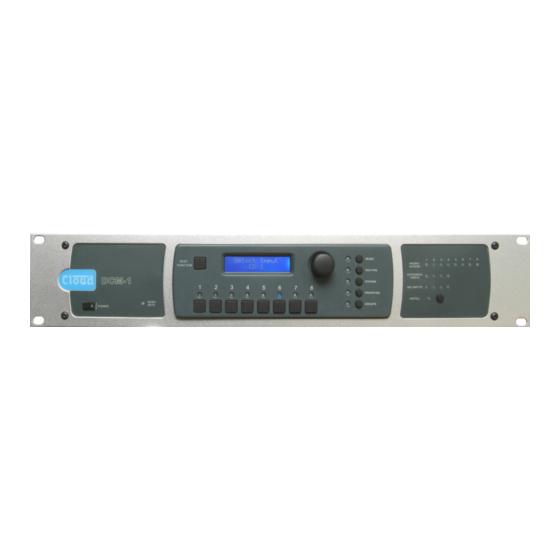
- Page 1 DCM1 & DCM1e Digitally Controlled Zone Mixers Installation and User Guide DCM1 & DCM1e Installation and User Guide v1.0...
-
Page 2: Safety Notes Regarding Installation
Safety Considerations and Safety Information Information Safety Notes regarding Installation The DCM1 and DCM1e are powered by separate Power • Do not expose the unit to water or moisture. Supply Units (PSUs), which must be earthed. Ensure that the •... -
Page 3: Scope Of This Manual
It is recognised that the tasks of design/set-up, physical Welcome installation and day-to-day operation of an audio system based on the DCM1 may be performed by as many as three Thank you for purchasing this Cloud DCM1/DCM1e, which different people. You will find, therefore, that this manual is... -
Page 4: Section 1: Overview
• Key-protected “Installer” mode (both DCM1 and An important aspect of the DCM1’s design is that it is CDR-1) prevents user access to configuration menus completely self-contained, and can if wished, be completely •... -
Page 5: System Components
Any zone may have one one of the DCM1’s Extension Ports with a single screened CDR-1, more than one, or none at all. The DCM1 can support Cat 5 cable. up to 100 CDR-1s. CDR-1s are interconnected with just one standard Cat 5 UTP cable;... -
Page 6: Pm Series Paging Microphones
ME-1 modules have adjustable mic level A description of each DCM1 menu function can be found in and EQ per input, and connect to one of the DCM1’s four the “Configuration” section of this manual: all corresponding dedicated Mic Inputs with a single screened Cat 5 cable. On... -
Page 7: System Capabilities
PAGING MICROPHONE INPUT Zone Outputs The simplified block diagram above illustrates the basic signal architecture of the DCM1. Only the routing and logic for one • Eight balanced line level zone outputs zone output is shown. • Zones 1 & 2 are stereo, 3 to 8 are mono... - Page 8 Internet be protected from Music Mute (e.g., for evac message, browser via network connection (DCM1e only) emergency mic, etc.) • Optional loudspeaker speaker EQ cards (per-zone) DCM1 & DCM1e Installation and User Guide V1.0...
-
Page 9: Applications And Examples
Applications and Examples The DCM1 will find applications in many types of premises, including shops, bars, hotels, schools, conference centres, offices, etc. The configurational flexibility of the DCM1 means that it can be set up by the system designer to provide precisely the facilities the user needs. - Page 10 CDPM/PM CDR-1 AREA 4 CDR-1 This shows a more complex system, which illustrates some additional DCM1 installation possibilities. Points to note: • • The large area has two CDR-1 remote controls in the Each half of the partitioned area also has an ME-1 mic same zone;...
- Page 11 Two of the line inputs are from LE-1 remote line input a security office. Other points to note: modules in two different zones. Other music sources have, in this case, been connected to Inputs 5 to 8. DCM1 & DCM1e Installation and User Guide v1.0...
-
Page 12: Section 2: Installation
Section 2: Installation Description of front panel 12 11 14 13 POWER button: applies DC power to the DCM1 9. PRIORITIES: allows assignment of priority inputs (note external PSU). (including paging inputs) and adjustment of the DCM1’s operation when priorities are active. -
Page 13: Description Of Rear Panel
This has several functions: it permits zone(s) to be paged. If a Cloud PM Series is the only control of the DCM1’s primary functions from an type of paging system being used, the connector can be... - Page 14 15. Music Mute input: 2-pin 5 mm-pitch screw terminal Ethernet commands generated elsewhere (future connector for interfacing the DCM1 to a fire alarm or firmware release). other emergency system. The input is configurable for...
-
Page 15: Hardware Considerations
If connecting a source with only a single mono output to The DCM1 is built in a 2U-high 19” rackmount enclosure. It the DCM1, connect it to both the L and R sockets, using a is strongly recommended that the DCM1 is installed Y-splitter lead or similar. -
Page 16: Standard Connection
BE-1 remote input modules connected Always avoid using pre-made leads of an unnecessary length. to EXTENSION PORTS 1 to 4; these could be installed adjacent to the DCM1 in such a situation. DCM1 & DCM1e Installation and User Guide V1.0... - Page 17 CDR-1 Remote Control Plates Multiple CDR-1 or CDR-1F remote control plates may be connected to the DCM1 either by wiring them directly and individually, or by “daisy-chaining” them together. In most installations, a combination of these methods is likely to be the most convenient solution from the point of view of practical cabling.
- Page 18 Cat 5 cable and RJ45 connectors. It may be possible to use pre-made Cat 5 “patch cables” to connect any CDR-1s installed close to the DCM1; otherwise Cat 5 cable and crimp RJ45 plugs should be used. NOTE: All Cat 5 cabling should be wired “pin-to-pin”;...
-
Page 19: Network Terminations
CDR-1s daisy-chained, and how • If both connectors on the same DCM1 CDR-1 PORT many of them are at a distance from the DCM1 close to the (either PORT A or PORT B) are being used, the maximum cable length. - Page 20 Remote input modules from the Cloud ME-1, LE-1 and BE-1 Note that the two mic inputs on the ME-1 and ME-1A remote ranges may be connected to the DCM1 in a similar manner modules are summed together and passed to the DCM1 as a to that described for the CDR-1 remote controls, except that mono signal.
-
Page 21: Connecting Paging Systems
“daisy-chained” together. For example, two microphones would be wired by connecting the OUT socket of one to the IN socket on the DCM1 BE-1 as above, and then connecting the OUT socket of the next microphone to the IN socket of the first. -
Page 22: Adjusting Paging Levels
ON. In Example 3 above, this will be at the paging microphone and DCM1 #2. The termination Zone 8 active in DCM1 #1 should be set to OFF (as it is in the +12 V “middle” of the chain). - Page 23 If the level restoration relay coils draw more than 60 mA per zone, additional intermediate relays and an external PSU must See page 69 for details of the DCM1’s PSU capabilities. be installed. The basic wiring scheme shown above is used, but now the “External relays”...
-
Page 24: Music Mute
It performs this function by default, though it can be re-defined in the menu system to provide per-zone control +12v outputs when used with Cloud PM paging microphones (see PAGING ACCESS CONNECTOR page 24). (Should a system require the use of both PM and third-party paging systems, control outputs will not be available if the connector is to be used in its “input”... -
Page 25: Section 3: Configuration
Section 3: Configuration The DCM1 can be configured in a variety of ways to suit all installed situations. Most configuration functions are accessed through the menu system. For convenience, the DCM1’s basic block diagram is repeated here: EXTENSION PORTS CDR-1 PORTS... - Page 26 Cloud DCM1 Installer configuration notes These tables should be filled in when the installation is complete to provide a record of the DCM1’s configuration. Table: see Installer_template.xls DCM1 & DCM1e Installation and User Guide V1.0...
- Page 27 DCM1 & DCM1e Installation and User Guide V1.0...
-
Page 28: Emc Considerations
EMC considerations Cloud DCM1 fully conforms to the relevant electromagnetic compatibility (EMC) standards and is technically well behaved; you should experience no operational problems, and under normal circumstances, no special precautions need to be taken. If the unit is to be installed in close proximity to potential sources of RF disturbance such as high power transmitting stations, radar facilities, etc., the performance of the mixer... - Page 29 Cloud Electronics Limited Cloud Electronics USA 140 Staniforth Road 2065 Sidewinder Drive Sheffield S9 3HF Suite 200, Park City England Utah 84060 Tel: +44 (0)114 244 7051 United States of America Fax: +44 (0)114 242 5462 Toll Free: 0855 810 0161 E-mail: info@cloud.co.uk...
Need help?
Do you have a question about the DCM1 and is the answer not in the manual?
Questions and answers