
Related Manuals for Cloud Z4MK4


Summary of Contents for Cloud Z4MK4
- Page 1 & Z8 ZONE MIXERS Installation and User Guide Z4-8 Installation and User Guide v1.2...
-
Page 2: Table Of Contents
Contents Safety Information ......................... 4 Important Safety Instructions ............................. 4 Read these instructions..............................4 Conformities ................................... 4 OVERVIEW ............................. 5 Introduction ..................................5 Scope of this manual ..............................5 What’s in the box ................................5 Main Features .................................. 5 Optional System Components ........................... - Page 3 Cloud Digital Paging Mics ............................18 Network termination .............................. 18 Zone Offset ................................19 Zone Outputs ................................19 EQ ....................................19 Priorities ..................................19 Mic 1/Mic 2 priority ..............................19 Paging mic priority ..............................19 Override of Paging mic priority during Music Mute ..................20 Line 6 priority ................................
-
Page 4: Safety Information
The lightning flash with the arrowhead symbol within Safety Information an equilateral triangle, is intended to alert you to the presence of uninsulated dangerous voltages within the Important Safety Instructions product’s enclosure that may be of sufficient magnitude to constitute a risk of electric shock. Read these instructions. -
Page 5: Overview
Introduction It is always a good idea to store all packaging (if practical), in case you ever need to return the unit to your Cloud dealer Thank you for purchasing this Cloud Zone Mixer. We are for any reason. -
Page 6: Optional System Components
They may also be retrofitted to a system at a later time. Separate datasheets are available for each of the individual components; download them at www.cloud.co.uk. LM-2 Mic/line input module with remote music control... -
Page 7: Pm Series Paging Microphones
PM Series paging microphones PM1 paging microphone The Cloud PM1 paging microphone is also compatible with the and Z4 . It is a much simpler unit which addresses Cloud PM paging microphones may be connected directly only one zone. See “Connecting a PM1 paging mic” on page... -
Page 8: Description Of Front Panel
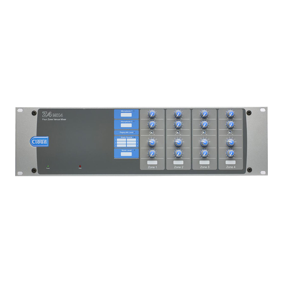
Description of front panel Note - The front panel of the Z8 is shown above. Note that the Z4 is identical, except that it only has controls for Zones 1 - 4. MUSIC SOURCE – 6-way rotary switch selecting which Line Input (1 to 6) will be the music source for each zone. See page 17. -
Page 9: Description Of Rear Panel
HF and LF – paging mic EQ; as [6]. See page 19. 10. CLOUD DIGITAL PAGING MIC – two RJ45 sockets (IN and THRU) for direct connection of Cloud PM and CDPM Series digital paging microphones. See “Cloud Digital Paging Mics” on page 18. -
Page 10: Installation
System Connections INSTALLATION Music Sources Hardware Considerations Connect the system’s various music sources to LINE 1 to The Z8 and Z4 Zone Mixers are built in 3U-high 19” LINE 6. Line Inputs 1 and 2 are unbalanced, on standard RCA rack mount enclosures. -
Page 11: Zone Outputs
Zone outputs However, the wiring method shown below will work in a large number of cases: Connect the inputs of the power amplifiers feeding the loudspeakers for each zone to the OUTPUT connectors for Zones 1 to 8*. Note that the zone outputs are all mono. The outputs are balanced and will drive input impedances Unbalanced down to 600 ohms. -
Page 12: Microphone Inputs
Microphone inputs The pinout of the Facility Port connector is given in the table below: MICROPHONE 1 and MICROPHONE 2 inputs are intended for the direct connection of microphones. They are Cat 5 CORE* electronically balanced and transformerless with an input Audio ‘cold’... -
Page 13: Paging System Connections
Z8 and Z4 . All models except the PM1 can use either the Cloud Digital Paging Interface or an industry-standard analogue interface; Model PM1 uses the analogue interface. PM microphones are available in 4, 8, 12 or 16-zone versions;... - Page 14 (either by a local PSU or via the network from another PM unit). The earlier Cloud CDPM Series of paging microphones is also PM8 PAGING MICROPHONE compatible with the Digital Paging Interface.
-
Page 15: Music Control
Cloud remote control plates from the RL-1 Series circuitry. However, if this method is to be employed, the mating... -
Page 16: Music Mute
Connecting an RSL-6 Series remote control plate Visual indication of muting being activated is given by the Mute LED on the front panel. Wire the remote control plate as shown below. Twin-and- screen cable should be used. Maximum reliable cable run is MUSIC MUTE 100 m. -
Page 17: Setting Up & Operation
Microphone Inputs SETTING UP & OPERATION Phantom Power Each primary microphone input (MICROPHONE 1 & Music Inputs MICROPHONE 2) has 12 V phantom power available. This will be adequate to power a wide range of condenser Gain & level microphones. (Some “studio quality” mics may require a To avoid dramatic changes in volume when switching between higher phantom voltage and thus necessitate an external sources, the Z8... -
Page 18: Paging Mic Input
Phantom Power The PAGING MIC input also has 12 V phantom power available. This will NOT be required if a Cloud paging microphone is being used with the mixer, but may be necessary CLOUD DIGITAL PAGING MIC with other manufacturers’... -
Page 19: Zone Offset
Note that if both the Digital Paging Mic Interface and the previously (page 17) to adjust the music level in each zone. Paging Mic Input are in use – e.g., with a Cloud PM Series mic and a third-party microphone using the analogue interface - the Digital Interface always has priority. -
Page 20: Override Of Paging Mic Priority During Music Mute
Override of Paging mic priority during Music Mute In some installations, it may be more appropriate for a microphone connected to the ‘non-paging’ mic inputs (MICROPHONE 1 and MICROPHONE 2) to take priority in an emergency situation. This can be achieved by moving J8 on the zone sub-boards from ‘EN’... -
Page 21: Options And Additional Information
OPTIONS AND ADDITIONAL INFORMATION LM-2 active input modules – general considerations Cloud LM-2 remote input modules are available in various form factors, to fit double-gang UK or other back boxes styles. Please refer to www.cloud.co.uk/accessories for details of the full range. Back boxes of either the recessed type or surface-mounting type may be used, providing they are at least 35 mm deep. -
Page 22: Rl-1 Series And Rsl-6 Series Remote Control Plates - General Considerations
RL-1 Series and RSL-6 Series remote control plates – general considerations Cloud RL-1 Series and RSL-6 Series remote control plates are available in three form factors: two fit single-gang UK or American electrical back boxes respectively, while the third is a 50 x 50 mm “Media” module, suitable for “Euro-module” mounting frames available in most European countries. -
Page 23: Fitting Loudspeaker Eq Cards
Please check the Cloud website (www.cloud.co.uk/accessories) for makes and models of loudspeakers for which EQ cards are available. -
Page 24: Appendix
• Area 3 has a Cloud PM paging microphone, which would be used to originate voice messages to any of the areas. The paging level to Area 3 (if required) would be adjusted on installation to be at a level that does not cause feedback. -
Page 25: Application Example 2
This example shows how two Zone Mixers – in this case one Z8 and one Z4 – can be used in conjunction with the Cloud Digital Paging Interface to allow a PM12 Paging Microphone to correctly address all 12 zones. SW2 settings: Termination: OFF... -
Page 26: Pcb Jumper Location And Settings
ZONE SUB-CARDS FRONT OF UNIT * Z8 ONLY MOTHERBOARD (at bottom of chassis) Motherboard jumper locations REMOTE SOURCE + LEVEL RJ45 FACILITY PORT ZONE OUTPUT (COMPONENT SIDE) SOCKET FOR OPTIONAL EQ CARD KEY: Jumper with two possible positions; black square indicates factory default setting. Zone sub-card jumper locations Z4-8 Installation and User Guide v1.2... -
Page 27: Psu Capability And Optional Device Current Consumption
(a club or microphone mixer for example) it would be perfectly normal to expect this to be earthed; we suggest that a transformer be used to isolate the signal and prevent a noisy loop (see page 10). EMC considerations The Cloud Z8 & Z4 fully conform to the relevant electromagnetic compatibility (EMC) standards and are technically well behaved;... -
Page 28: Technical Specifications
Technical Specifications & Z8 Line Inputs: Frequency Response 20 Hz – 20 kHz ±0.5 dB Distortion <0.08% 20 Hz - 20 kHz Sensitivity -11 dBu (218 mV) to +12.5 dBu (3.2V), +/0.5 dBu Input Gain Control 20 dB (unbal i/p’s); 22 dB (bal i/p’s) Input Impedance 47 kohms Headroom... - Page 29 Z4-8 Installation and User Guide v1.2...
- Page 30 Z4-8 Installation and User Guide v1.2...
- Page 31 www.cloudusa.pro...
Need help?
Do you have a question about the Z4MK4 and is the answer not in the manual?
Questions and answers