Table of Contents
Advertisement
Quick Links
Advertisement
Table of Contents

Related Manuals for ThinkPad R500


Summary of Contents for ThinkPad R500
- Page 1 ThinkPad R500 Hardware Maintenance Manual...
- Page 3 ThinkPad R500 Hardware Maintenance Manual...
- Page 4 Note Before using this information and the product it supports, be sure to read the general information under “Notices” on page 215. Fourth Edition (July 2013) © Copyright Lenovo 2008, 2013. LENOVO products, data, computer software, and services have been developed exclusively at private expense and are sold to governmental entities as commercial items as defined by 48 C.F.R.
-
Page 5: Table Of Contents
Contents About this manual ..v Symptom-to-FRU index . . 62 Numeric error codes . . 62 Error messages . . 66 Safety information ..1 Beep symptoms . - Page 6 Notices ....215 DVDs . . 198 Windows Vista Home Basic (32 bit) recovery Trademarks . . 216 DVDs . . 199 Windows Vista Home Premium (32 bit) recovery DVDs . . 201 ThinkPad R500 Hardware Maintenance Manual...
-
Page 7: About This Manual
ThinkPad products. Use this manual along with the advanced diagnostic tests to troubleshoot problems effectively. Before servicing a ThinkPad product, be sure to read all the information under “Safety information” on page 1 and “Important service information” on page 39. - Page 8 ThinkPad R500 Hardware Maintenance Manual...
-
Page 9: Safety Information
Safety information This chapter presents following safety information that you need to be familiar with before you service a ThinkPad Notebook. v “General safety” on page 2 v “Electrical safety” on page 3 v “Safety inspection guide” on page 5 v “Handling devices that are sensitive to electrostatic discharge”... -
Page 10: General Safety
Reinstall all covers correctly before returning the machine to the customer. v Fan louvers on the machine help to prevent overheating of internal components. Do not obstruct fan louvers or cover them with labels or stickers. ThinkPad R500 Hardware Maintenance Manual... -
Page 11: Electrical Safety
Electrical safety Observe the following rules when working on electrical equipment. Important: Use only approved tools and test equipment. Some hand tools have handles covered with a soft material that does not insulate you when working with live electrical currents. Many customers have, near their equipment, rubber floor mats that contain small conductive fibers to decrease electrostatic discharges. - Page 12 This practice ensures correct grounding of the units. v If an electrical accident occurs: – Use caution; do not become a victim yourself. – Switch off power. – Send another person to get medical aid. ThinkPad R500 Hardware Maintenance Manual...
-
Page 13: Safety Inspection Guide
4. Check for cracked or bulging batteries. 5. Remove the cover. 6. Check for any obvious non-ThinkPad alterations. Use good judgment as to the safety of any non-ThinkPad alterations. 7. Check inside the unit for any obvious unsafe conditions, such as metal filings, contamination, water or other liquids, or signs of fire or smoke damage. -
Page 14: Handling Devices That Are Sensitive To Electrostatic Discharge
– Use the round ground prong of the ac plug on ac-operated computers. Grounding requirements Electrical grounding of the computer is required for operator safety and correct system function. Proper grounding of the electrical outlet can be verified by a certified electrician. ThinkPad R500 Hardware Maintenance Manual... -
Page 15: Safety Notices (Multilingual Translations)
Safety notices (multilingual translations) The safety notices in this section are provided in the following languages: v English v Arabic v Brazilian Portuguese v French v German v Hebrew v Japanese v Korean v Spanish v Traditional Chinese Safety information... - Page 16 If the LCD breaks and the fluid from inside the LCD gets into your eyes or on your hands, immediately wash the affected areas with water for at least 15 minutes. Seek medical care if any symptoms from the fluid are present after washing. ThinkPad R500 Hardware Maintenance Manual...
- Page 17 DANGER To avoid shock, do not remove the plastic cover that protects the lower part of the inverter card. DANGER Though the main batteries have low voltage, a shorted or grounded battery can produce enough current to burn personnel or combustible materials. DANGER Unless hot swap is allowed for the FRU being replaced, do as follows before removing it: power off the computer, unplug all power cords from electrical outlets, remove the...
- Page 18 ThinkPad R500 Hardware Maintenance Manual...
- Page 19 Safety information...
- Page 20 Se o LCD quebrar e o fluido de dentro dele entrar em contato com seus olhos ou com suas mãos, lave as áreas afetadas imediatamente com água durante pelo menos 15 minutos. Procure cuidados médicos se algum sintoma causado pelo fluido surgir após a lavagem. ThinkPad R500 Hardware Maintenance Manual...
- Page 21 PERIGO Para evitar choque elétrico, não remova a capa plástica que protege a parte inferior da placa inversora. PERIGO Embora as principais baterias possuam baixa voltagem, uma bateria em curto-circuito ou aterrada pode produzir corrente o bastante para queimar materiais de pessoal ou inflamáveis.
- Page 22 Si le panneau d’affichage à cristaux liquides se brise et que vous recevez dans les yeux ou sur les mains une partie du fluide, rincez-les abondamment pendant au moins quinze minutes. Consultez un médecin si des symptômes persistent après le lavage. ThinkPad R500 Hardware Maintenance Manual...
- Page 23 DANGER Afin d’éviter tout risque de choc électrique, ne retirez pas le cache en plastique protégeant la partie inférieure de la carte d’alimentation. DANGER Bien que le voltage des batteries principales soit peu élevé, le court-circuit ou la mise à la masse d’une batterie peut produire suffisamment de courant pour brûler des matériaux combustibles ou causer des brûlures corporelles graves.
- Page 24 Polung angebrachte Verbindungsstecker entfernt werden. Bei der Entsorgung die örtlichen Bestimmungen für Sondermüll beachten. Beim Ersetzen der Batterie nur Batterien des Typs verwenden, der in der Ersatzteilliste aufgeführt ist. Der Einsatz falscher Batterien kann zu Entzündung oder Explosion führen. ThinkPad R500 Hardware Maintenance Manual...
- Page 25 VORSICHT Die Leuchtstoffröhre im LCD-Bildschirm enthält Quecksilber. Bei der Entsorgung die örtlichen Bestimmungen für Sondermüll beachten. Der LCD-Bildschirm besteht aus Glas und kann zerbrechen, wenn er unsachgemäß behandelt wird oder der Computer auf den Boden fällt. Wenn der Bildschirm beschädigt ist und die darin befindliche Flüssigkeit in Kontakt mit Haut und Augen gerät, sollten die betroffenen Stellen mindestens 15 Minuten mit Wasser abgespült und bei Beschwerden anschließend ein Arzt aufgesucht werden.
- Page 26 ThinkPad R500 Hardware Maintenance Manual...
- Page 27 Safety information...
- Page 28 ThinkPad R500 Hardware Maintenance Manual...
- Page 29 Safety information...
- Page 30 ThinkPad R500 Hardware Maintenance Manual...
- Page 31 Safety information...
- Page 32 Si la LCD se rompe y el fluido de su interior entra en contacto con sus ojos o sus manos, lave inmediatamente las áreas afectadas con agua durante 15 minutos como mínimo. Obtenga atención medica si se presenta algún síntoma del fluido despues de lavarse. ThinkPad R500 Hardware Maintenance Manual...
- Page 33 PELIGRO Para evitar descargas, no quite la cubierta de plástico que rodea la parte baja de la tarjeta invertida. PELIGRO Aunque las baterías principales tienen un voltaje bajo, una batería cortocircuitada o con contacto a tierra puede producir la corriente suficiente como para quemar material combustible o provocar quemaduras en el personal.
- Page 34 ThinkPad R500 Hardware Maintenance Manual...
- Page 35 Safety information...
-
Page 36: Laser Compliance Statement (Multilingual Translations)
Spanish v Traditional Chinese Some models of ThinkPad Notebook are equipped from the factory with an optical storage device such as a CD-ROM drive or a DVD-ROM drive. Such devices are also sold separately as options. If one of these drives is installed, it is certified in the U.S. - Page 37 Safety information...
- Page 38 Alguns modelos de computador ThinkPad são equipados na fábrica com um dispositivo de armazenamento ótico, como uma unidade de CD-ROM ou de DVD-ROM. Tais dispositivos também são vendidos separadamente como opcionais. Se uma dessas unidades estiver instalada, ela é certificada nos Estados Unidos em conformidade com os requisitos do Department of Health and Human Services 21 Code of Federal Regulations (DHHS 21 CFR), Subcapítulo J, para...
- Page 39 Certains modèles d’ordinateur ThinkPad sont équipés d’origine d’une unité de stockage optique telle qu’une unité de CD-ROM ou de DVD-ROM. Ces unités sont également vendues séparément en tant qu’options. Si l’une de ces unités est installée, elle est certifiée conforme, aux Etats-Unis, aux normes indiquées dans le sous-chapitre J du DHHS 21 CFR relatif aux produits à...
- Page 40 Einige ThinkPad-Modelle sind werkseitig mit einem CD-ROM- oder DVD-ROM-Laufwerk ausgestattet. CD- und DVD-Laufwerke können auch gesondert als Zusatzeinrichtung erworben werden. Die Laufwerke erfüllen die Anforderungen gemäß IEC 60825-1 (International Electrotechnical Commission) und gemäß CENELEC EN 60825-1 für Laserprodukte der Klasse 1.
- Page 41 Safety information...
- Page 42 ThinkPad R500 Hardware Maintenance Manual...
- Page 43 Safety information...
- Page 44 Algunos modelos de sistemas ThinkPad están equipados de fábrica con un dispositivo de almacenamiento óptico, como una unidad de CD-ROM o de DVD-ROM. Estas unidades también se venden por separado como opciones. Si está instalada alguna de dichas unidades, se certifica que en los Estados Unidos cumple los requisitos del Department of Health and Human Services 21 Code of Federal Regulations (DHHS 21 CFR) Subchapter J para productos láser de Clase 1.
- Page 45 Safety information...
- Page 46 ThinkPad R500 Hardware Maintenance Manual...
-
Page 47: Important Service Information
Important service information This chapter presents following important service information that applies to all machine types supported by this manual: v “Strategy for replacing FRUs” – “Strategy for replacing a hard disk drive” on page 40 – “Important notice for replacing a system board” on page 40 –... -
Page 48: Strategy For Replacing A Hard Disk Drive
Whatever causes the first error code may also cause false error codes. If no error code is displayed, see whether the error symptom is listed in the Symptom-to-FRU Index for the computer you are servicing. ThinkPad R500 Hardware Maintenance Manual... -
Page 49: Strategy For Replacing Frus For Cto, Cmv, And Gav
Strategy for replacing FRUs for CTO, CMV, and GAV Product definition Dynamic Configure To Order (CTO) ® This provides the ability for a customer to configure an IBM or a Lenovo solution from an eSite, and have this configuration sent to fulfillment, where it is built and shipped directly to the customer. - Page 50 For Key Commodities (Examples - hard disk drive, system board, microprocessor, LCD, and memory) Use the HMM as a back-up to PEW and eSupport to view the complete list of FRUs at the MT Model level. ThinkPad R500 Hardware Maintenance Manual...
-
Page 51: General Checkout
– “PC-Doctor for Windows” on page 48 – “PC-Doctor for Rescue and Recovery” on page 49 v “Power system checkout” on page 52 The descriptions in this chapter apply to any ThinkPad model that supports the ® PC-Doctor for DOS diagnostics program. Some descriptions might not apply to your particular computer. -
Page 52: What To Do First
The following symptoms might indicate damage caused by nonwarranted activities: v Missing parts might be a symptom of unauthorized service or modification. v If the spindle of a hard disk drive becomes noisy, it may have been subjected to excessive force, or dropped. ThinkPad R500 Hardware Maintenance Manual... -
Page 53: Checkout Guide
Use the following procedures as a guide in identifying and correcting problems with the ThinkPad Notebook. Note: The diagnostic tests are intended to test only ThinkPad products. The use of non-ThinkPad products, prototype cards, or modified options can lead to false indications of errors and invalid system responses. -
Page 54: Testing The Computer
52, and check the power sources. If an error code appears, go to “Symptom-to-FRU index” on page 62. 4. When the ThinkPad logo comes up, immediately press F12 to enter the Boot Menu. 5. Insert the PC-Doctor CD into the internal optical drive. - Page 55 DOS. v To test Digital Signature Chip, the security chip must be set to Active. v To test Serial Ports or Parallel Ports, the ThinkPad Notebook must be attached to the docking station. 10. Run the applicable function test.
-
Page 56: Lenovo Thinkvantage Toolbox (Lenovo System Toolbox)
For additional information about this program, see the Help for the program. PC-Doctor for Windows In some models of ThinkPad Notebook, PC-Doctor for Windows enables you to troubleshoot and resolve problems related to the computer. Select one of the categories listed below to display symptoms and solutions:... -
Page 57: Pc-Doctor For Rescue And Recovery
System Reports v Updates and Support PC-Doctor for Rescue and Recovery ® In some models of ThinkPad Notebook, the Rescue and Recovery workspace enables you to run the PC-Doctor program to test the hardware features of the computer. To run the test, click “Run Diagnostics” on the Rescue and Recovery main screen. -
Page 58: Fru Tests
1. Diagnostics --> CPU/Coprocessor 2. Diagnostics --> Systemboard 3. If the docking station or the port replicator is attached to the ThinkPad computer, detach it. Place the computer on a horizontal surface, and run Diagnostics --> ThinkPad Devices --> HDD Active Protection Test. - Page 59 1. Turn on the computer and check the air turbulence at the louver near the PC Card slot. 2. Run Diagnostics --> ThinkPad Devices --> Fan. TrackPoint or pointing If the TrackPoint does not work, check the configuration as device specified in the BIOS Setup Utility.
-
Page 60: Power System Checkout
4. If the voltage is acceptable, do the following: v Replace the system board. v If the problem persists, go to “FRU tests” on page 50. Note: Noise from the AC adapter does not always indicate a defect. ThinkPad R500 Hardware Maintenance Manual... -
Page 61: Checking Operational Charging
Checking operational charging To check whether the battery charges properly during operation, use a discharged battery pack or a battery pack that has less than 50% of the total power remaining when installed in the computer. Perform operational charging. If the battery status indicator or icon does not turn on, remove the battery pack and let it return to room temperature. -
Page 62: Checking The Backup Battery
Ground v If the voltage is correct, replace the system board. v If the voltage is not correct, replace the backup battery. v If the backup battery discharges quickly after replacement, replace the system board. ThinkPad R500 Hardware Maintenance Manual... -
Page 63: Related Service Information
Related service information This chapter presents following information: v “Restoring the factory contents by using Product Recovery discs” v “Restoring the factory contents by using Recovery Disc Set” on page 56 v “Passwords” on page 57 v “Power management” on page 60 v “Symptom-to-FRU index”... -
Page 64: Restoring The Factory Contents By Using Recovery Disc Set
2. Insert the Operating System Recovery Disc into the DVD drive. 3. Press F10 to save the Setup Utility configuration changes. Follow the instructions on the screen to begin the recovery process. 4. Select your language and click Next. ThinkPad R500 Hardware Maintenance Manual... -
Page 65: Passwords
Note: After restoring a hard disk drive to the factory default settings, you might need to reinstall some device drivers. Passwords As many as three passwords may be needed for any ThinkPad Notebook: the power-on password (POP), the hard-disk password (HDP), and the supervisor password (SVP). -
Page 66: Supervisor Password
(B) If an SVP has been set and is known by the service technician: 1. Turn on the computer. 2. When the ThinkPad logo comes up, immediately press F1 to enter BIOS Setup Utility. For models supporting the Passphrase function, press F1 while the POP icon is appearing on the screen;... -
Page 67: How To Remove The Hard-Disk Password
To remove a user HDP that has been forgotten, when the SVP and the master HDP are known, do the following: 1. Turn on the computer. 2. When the ThinkPad logo comes up, immediately press F1 to enter BIOS Setup Utility. For models supporting the Passphrase function, press F1 while HDP icon is appearing on the screen;... -
Page 68: Power Management
To cause the computer to return from sleep (standby) mode and resume operation, do one of the following: v Press the Fn key. v Open the LCD cover. v Turn on the power switch. ThinkPad R500 Hardware Maintenance Manual... -
Page 69: Hibernation Mode
Also, in either of the following events, the computer automatically returns from sleep (standby) mode and resumes operation: v The ring indicator (RI) is signaled by a serial device or a PC Card device. v The time set on the resume timer elapses. Note: The computer does not accept any input immediately after it enters sleep (standby) mode. -
Page 70: Symptom-To-Fru Index
If no numeric code is displayed, check the narrative descriptions of symptoms. If the symptom is not described there, go to “Intermittent problems” on page 69. Note: For a device not supported by diagnostic codes in the ThinkPad Notebooks, see the manual for that device. Numeric error codes Table 2. - Page 71 Table 2. Numeric error codes (continued) Symptom or error FRU or action, in sequence 0187 System board. EAIA data access error—The access to EEPROM is failed. 0188 System board. Invalid RFID Serialization Information Area. 0189 System board. Invalid RFID configuration information area—The EEPROM checksum is not correct.
- Page 72 2. System board. in—Turn off and remove the miniPCI network card. 1803 1. Remove the daughter card that you Unauthorized daughter card is plugged installed. in—Turn off and remove the daughter card. 2. System board. ThinkPad R500 Hardware Maintenance Manual...
- Page 73 <Esc> to ThinkPad Notebook. continue.Press <F1> to enter SETUP 2. Place the ThinkPad Notebook on a horizontal surface. Do not apply any physical shock to the computer. 3. Run Diagnostics --> ThinkPad Devices -->...
-
Page 74: Error Messages
1. Check that the operating system has no failure and is installed correctly. 2. Reinstall the operation system. Excluded from boot order. v Enter the BIOS Setup Utility and add the device in boot order. ThinkPad R500 Hardware Maintenance Manual... -
Page 75: Beep Symptoms
Beep symptoms Table 4. Beep symptoms Symptom or error FRU or action, in sequence One beep and a blank, unreadable, or 1. Reseat the LCD connector. flashing LCD. 2. LCD assembly. 3. External CRT. 4. System board. One long and two short beeps, and a blank 1. -
Page 76: Lcd-Related Symptoms
Lenovo and it should be replaced. Notes: v This policy applies to all ThinkPad Notebooks purchased on 1 January, 2008 or later. v Lenovo will not provide replacement if the LCD is within specification as we cannot guarantee that any replacement LCD will have zero pixel defects. -
Page 77: Intermittent Problems
2. Visually check each FRU for damage. Replace any damaged FRU. 3. Remove or disconnect all of the following devices: a. Non-ThinkPad devices b. Devices attached to the docking station or the port replicator c. Printer, mouse, and other external devices d. - Page 78 ThinkPad R500 Hardware Maintenance Manual...
-
Page 79: Status Indicators
Status indicators This chapter presents the system status indicators that show the status of the computer. © Copyright Lenovo 2008, 2013... - Page 80 Green: The computer is connected to the ac power supply. status Sleep (standby) Green: The computer is in sleep (standby) mode. status Blinking green: The computer is entering sleep (standby) mode or hibernation mode, or is resuming normal operation. ThinkPad R500 Hardware Maintenance Manual...
- Page 81 Table 7. Status indicators (continued) Indicator Meaning Serial Ultrabay Green: A Serial Ultrabay Enhanced device is installed and in Enhanced status use. Blinking green: A Serial Ultrabay Enhanced device is in the process of being detached. Turn off: A Serial Ultrabay Enhanced device is ready to be attached or detached.
- Page 82 ThinkPad R500 Hardware Maintenance Manual...
-
Page 83: Fn Key Combinations
When you press this combination, a panel for selecting a power plan (power scheme) appears. Notes: 1. To use the Fn+F3 key combination, you must have the ThinkPad PM device driver installed on the computer. 2. If you have logged on with an administrator user ID, and you press Fn+F3, the panel for selecting a power plan (power scheme) appears. - Page 84 Fn+F9 Open the ThinkPad EasyEject Utility screen. Buttons for the following choices are displayed: v Eject ThinkPad PC from Dock: This button is displayed only if the docking station. The computer can be detached from the docking station. v Eject ThinkPad PC from Mini Dock: This button is displayed only if the ThinkPad computer has been attached to a port replicator and one or more USB devices have been connected to the port replicator.
- Page 85 Fn+F12 Put the computer into hibernation mode. To return to normal operation, press the power button for less than four seconds. Note: To use Fn+F12 for hibernation, you must have the ThinkPad PM device driver installed on the computer. ®...
- Page 86 ThinkPad R500 Hardware Maintenance Manual...
-
Page 87: Fru Replacement Notices
This chapter presents notices related to removing and replacing parts. Read this chapter carefully before replacing any FRU. Screw notices Loose screws can cause a reliability problem. In the ThinkPad Notebook, this problem is addressed with special nylon-coated screws that have the following characteristics: v They maintain tight connections. -
Page 88: Retaining Serial Numbers
Before replacing the system board, save the original serial number by doing the following: 1. Install the ThinkPad Hardware Maintenance Diskette Version 1.73 or later, and restart the computer. 2. From the main menu, select 1. Set System Identification. -
Page 89: Reading Or Writing The Eca Information
When you replace the system board, you must set the UUID on the new system board as follows: 1. Install the ThinkPad Hardware Maintenance Diskette Version 1.73 or later, and restart the computer. 2. From the main menu, select 4. Assign UUID. - Page 90 ThinkPad R500 Hardware Maintenance Manual...
-
Page 91: Removing And Replacing A Fru
Removing and replacing a FRU This chapter presents directions and drawings for use in removing and replacing a FRU. Be sure to observe the following general rules: 1. Do not try to service any computer unless you have been trained and certified. An untrained person runs the risk of damaging parts. -
Page 92: 1010 Battery Pack
2 , remove the battery pack in the direction shown by arrow When installing: Install the battery pack along the slide rails of the slot. Then make sure that the battery release lever is in the locked position. ThinkPad R500 Hardware Maintenance Manual... -
Page 93: 1020 Serial Ultrabay Enhanced Device
1020 Serial Ultrabay Enhanced device Note: Serial Ultrabay Enhanced does not accept any of the following devices: v Ultrabay Plus devices v Ultrabay 2000 devices Table 10. Removal steps of Serial Ultrabay Enhanced device for R61 and R61i When you release the switch in step 1 , the lever pops out. In step 2 , pull the lever a little to release the device from the bay. -
Page 94: 1030 Hard Disk Drive Cover, Hard Disk Drive, And Hard Disk Rubber Rails
Table 11. Removal steps of hard disk drive cover, hard disk drive, and hard disk rubber rails Step Screw (quantity) Color Torque Hard disk drive screw (M2 × 17 mm), Black 0.167 Nm flat-head, nylon-coated (1) (1.7 kgfcm) ThinkPad R500 Hardware Maintenance Manual... - Page 95 Table 11. Removal steps of hard disk drive cover, hard disk drive, and hard disk rubber rails (continued) When installing: Make sure that the hard disk drive connector is attached firmly. When installing: The rubber rails on the hard disk drive must be attached to the replacement drive.
-
Page 96: 1040 Palm Rest Or Palm Rest With Fingerprint Reader
Table 12. Removal steps of palm rest Step Icon Screw (quantity) Color Torque M2 × 17 mm, flat-head, Black 0.167 Nm nylon-coated (4) (1.7 kgfcm) ThinkPad R500 Hardware Maintenance Manual... - Page 97 Table 12. Removal steps of palm rest (continued) When installing: When you attach the palm rest, do as follows: 1. Attach the fingerprint reader connector firmly to the system board. Removing and replacing a FRU...
- Page 98 3. Push the front side of the palm rest until it clicks into place. 4. Close the LCD cover and turn the computer over. Then fasten the four screws to secure the palm rest. ThinkPad R500 Hardware Maintenance Manual...
-
Page 99: 1050 Dimm
1050 DIMM For access, remove these FRUs, in order: v “1010 Battery pack” on page 84 v “1040 Palm rest or palm rest with fingerprint reader” on page 88 Table 13. Removal steps of dimm Note: If only one DIMM is used on the computer you are servicing, the card must be installed in SLOT-0 ( a ), but not in SLOT-1 ( b ). -
Page 100: 1060 Keyboard
Screw (quantity) Color Torque M2 × 17 mm, flat-head, Black 0.167 Nm nylon-coated (1) (1.7 kgfcm) Lift the keyboard a little in the direction shown by arrow 2 , and then detach the connector 3 . ThinkPad R500 Hardware Maintenance Manual... - Page 101 Table 14. Removal steps of keyboard (continued) When installing: Make sure that the keyboard edges a are under the frame as shown in this figure. Removing and replacing a FRU...
-
Page 102: 1070 Pci Express Mini Card For Wireless Lan
Note: Some models might have three antenna cables in step 1 . Step Screw (quantity) Color Torque M2 × 9.5 mm, flat-head, nylon-coated (2) Black 0.167 Nm (1.7 kgfcm) ThinkPad R500 Hardware Maintenance Manual... - Page 103 Table 15. Removal steps of PCI Express Mini Card for wireless LAN (continued) When installing: In models with wireless LAN card that has two antenna connectors, plug the gray cable into the jack labeled MAIN or M on the card, and the black cable into the jack labeled AUX or A.
- Page 104 (P/N: 08K7159) or pick the connectors with your fingers and gently unplug them in direction of the arrow. Step Screw (quantity) Color Torque M2 × 3 mm, flat-head, nylon-coated (2) Silver 0.167 Nm (1.7 kgfcm) ThinkPad R500 Hardware Maintenance Manual...
- Page 105 Table 15. Removal steps of PCI Express Mini Card for wireless LAN (continued) When installing: Plug the gray cable into the jack labeled MAIN on the card, and the black cable into the jack labeled AUX. Removing and replacing a FRU...
-
Page 106: 1080 Intel Turbo Memory Minicard
“1040 Palm rest or palm rest with fingerprint reader” on page 88 v “1060 Keyboard” on page 92 Table 16. Removal steps of Intel Turbo Memory Step Screw (quantity) Color Torque M2 × 3 mm, flat-head, nylon-coated (2) Silver 0.167 Nm (1.7 kgfcm) ThinkPad R500 Hardware Maintenance Manual... -
Page 107: 1090 Backup Battery
1090 Backup battery DANGER Use only the battery specified in the parts list for your computer. Any other battery could ignite or explode. For access, remove these FRUs in order: v “1010 Battery pack” on page 84 v “1040 Palm rest or palm rest with fingerprint reader” on page 88 v “1060 Keyboard”... -
Page 108: 1100 Keyboard Bezel And Speakers
Note: Speakers are attached to the underside of the keyboard bezel. Step Screw (quantity) Color Torque M2 × 3 mm, flat-head, nylon-coated (1) Silver 0.167 Nm (1.7 kgfcm) Step Screw (quantity) Color Torque M2 × 17 mm, flat-head, nylon-coated (2) Black 0.167 Nm (1.7 kgfcm) ThinkPad R500 Hardware Maintenance Manual... - Page 109 Table 18. Removal steps of keyboard bezel and speakers (continued) In step 3 , release the wireless antenna cables from the cable guide. Step Screw (quantity) Color Torque M2 × 3 mm, flat-head, nylon-coated (6) Silver 0.167 Nm (1.7 kgfcm) In step 5 , strip the securing tapes off.
- Page 110 In step 7 , detach the claws. Then remove the keyboard bezel in the direction shown by arrow 8 . When installing: Make sure that all the claws are attached firmly. Step Screw (quantity) Color Torque M2 × 3 mm, flat-head, nylon-coated (4) Silver 0.167 Nm (1.7 kgfcm) ThinkPad R500 Hardware Maintenance Manual...
-
Page 111: 1110 Fan Assembly
1110 Fan assembly For access, remove these FRUs, in order: v “1010 Battery pack” on page 84 v “1040 Palm rest or palm rest with fingerprint reader” on page 88 v “1060 Keyboard” on page 92 v “1100 Keyboard bezel and speakers” on page 100 Table 19. - Page 112 Step Screw (quantity) Color Torque M2 × 9.5 mm, flat-head, nylon-coated (2) Black 0.167 Nm (1.7 kgfcm) In step 5 , release the wireless antenna cables from the cable guide of the fan assembly. ThinkPad R500 Hardware Maintenance Manual...
- Page 113 Table 19. Removal steps of fan assembly (continued) When installing: v Before you attach the fan assembly to the computer, apply thermal grease, at an amount of 0.2 grams, on the part marked a as in the following figure. Either too much or too less application of grease can cause a thermal problem due to imperfect contact with a component.
- Page 114 Table 19. Removal steps of fan assembly (continued) v Make sure that the fan connector is attached firmly. v When attaching the fan assembly to the frame, take care not to damage the heat sink ( b ) of the fan assembly. ThinkPad R500 Hardware Maintenance Manual...
-
Page 115: 1120 Cpu
1120 CPU For access, remove these FRUs, in order: v “1010 Battery pack” on page 84 v “1040 Palm rest or palm rest with fingerprint reader” on page 88 v “1060 Keyboard” on page 92 v “1100 Keyboard bezel and speakers” on page 100 v “1110 Fan assembly”... -
Page 116: 1130 Lcd Assembly
“1070 PCI Express Mini Card for wireless LAN” on page 94 v “1100 Keyboard bezel and speakers” on page 100 Table 21. Removal steps of LCD assembly Step Screw (quantity) Color Torque M2 × 9.5 mm, flat-head, nylon-coated (2) Black 0.167 Nm (1.7 kgfcm) ThinkPad R500 Hardware Maintenance Manual... - Page 117 Table 21. Removal steps of LCD assembly (continued) Step Screw (quantity) Color Torque M2.5 × 6.5 mm, flat-head, nylon-coated (2) Black 0.167 Nm (1.7 kgfcm) In step 4 , strip off the tapes securing the antenna cables, and release the cables from the cable guides of the frame.
- Page 118 As you route the cables, make sure that they are not subjected to any tension. Tension could cause the cables to be damaged by the cable guides, or a wire to be broken. 2. Make sure that the LCD connector is attached firmly. ThinkPad R500 Hardware Maintenance Manual...
-
Page 119: 1140 Base Cover And Pc Card/Expresscard (Or Expresscard/Smart Card) Bezel Assembly
1140 Base cover and PC Card/ExpressCard (or ExpressCard/Smart Card) bezel assembly For access, remove these FRUs, in order: v “1010 Battery pack” on page 84 v “1020 Serial Ultrabay Enhanced device” on page 85 v “1030 Hard disk drive cover, hard disk drive, and hard disk rubber rails” on page 86 v “1040 Palm rest or palm rest with fingerprint reader”... - Page 120 Table 22. Removal steps of base cover and PC Card/ExpressCard (or ExpressCard/Smart Card) bezel assembly (continued) Step Screw (quantity) Color Torque M2 × 9.5 mm, flat-head, nylon-coated (1) Black 0.167 Nm (1.7 kgfcm) M2 × 17 mm, flat-head, nylon-coated (2) Black 0.167 Nm (1.7 kgfcm) ThinkPad R500 Hardware Maintenance Manual...
- Page 121 Table 22. Removal steps of base cover and PC Card/ExpressCard (or ExpressCard/Smart Card) bezel assembly (continued) Step Screw (quantity) Color Torque M2 × 5 mm, flat-head, nylon-coated (2) Black 0.167 Nm(1.7 kgfcm) Removing and replacing a FRU...
- Page 122 It must be housed in its position as shown in the figure a . When installing: Check the position of the wireless switch b , and firmly fit the structure frame into the base cover. ThinkPad R500 Hardware Maintenance Manual...
- Page 123 Table 22. Removal steps of base cover and PC Card/ExpressCard (or ExpressCard/Smart Card) bezel assembly (continued) Remove the security hole bracket as in this figure. Step Screw (quantity) Color Torque M2 × 3 mm, flat-head, nylon-coated (1) Silver 0.167 Nm(1.7 kgfcm) Removing and replacing a FRU...
- Page 124 Remove the RJ11 cable a and the optical drive switch cable b as in this figure. In step 2 , strip the securing taps off. Step Screw (quantity) Color Torque M2 × 3 mm, flat-head, nylon-coated (2) Silver 0.167 Nm(1.7 kgfcm) ThinkPad R500 Hardware Maintenance Manual...
- Page 125 Table 22. Removal steps of base cover and PC Card/ExpressCard (or ExpressCard/Smart Card) bezel assembly (continued) When removing the PC Card/ExpressCard bezel assembly, do as shown in this figure. When removing the ExpressCard/Smart Card bezel assembly, do as shown in this figure.
- Page 126 FCC labels, find duplicates of them in the label kit and apply them to the new base cover. For the location of each label, refer the following figure: ThinkPad R500 Hardware Maintenance Manual...
-
Page 127: 1150 Structure Frame And Ieee 1394 Sub Card
1150 Structure frame and IEEE 1394 sub card For access, remove these FRUs, in order: v “1010 Battery pack” on page 84 v “1020 Serial Ultrabay Enhanced device” on page 85 v “1030 Hard disk drive cover, hard disk drive, and hard disk rubber rails” on page 86 v “1040 Palm rest or palm rest with fingerprint reader”... - Page 128 Table 23. Removal steps of structure frame and IEEE 1394 sub card (continued) Remove the ac power jack cable a . When installing: Make sure the connectors are attached firmly. ThinkPad R500 Hardware Maintenance Manual...
- Page 129 Table 23. Removal steps of structure frame and IEEE 1394 sub card (continued) Remove the CPU support plate. Step Screw (quantity) Color Torque M2 × 5 mm, flat-head, nylon-coated (1) Black 0.167 Nm (1.7 kgfcm) Removing and replacing a FRU...
- Page 130 M2 × 9.5 mm, flat-head, nylon-coated (1) Black 0.167 Nm (1.7 kgfcm) When installing: When attaching the system board to the frame, adjust the placement with the small projection a . Then secure the system board with the screws. ThinkPad R500 Hardware Maintenance Manual...
- Page 131 Table 23. Removal steps of structure frame and IEEE 1394 sub card (continued) In step 10 , remove the system board and the PC Card/ExpressCard slots assembly from the structure frame together. In step 11 and 12 , remove IEEE 1394 sub card. Step Screw (quantity) Color...
-
Page 132: 1160 System Board, Pc Card/Expresscard Slots (Or Expresscard/Smart Card Slots) Assembly
HDD Active Protection still functions. The procedure is as follows: 1. Place the computer on a horizontal surface. 2. Run Diagnostics --> ThinkPad Devices --> HDD Active Protection Test. Attention: Do not apply physical shock to the computer while the test is running. - Page 133 Following components soldered on the top side of the system board are extremely sensitive. When you service the system board, avoid any kind of rough handling. Video chip (Discrete graphics chip models only.) MCH (Memory Controller Hub) ICH (I/O Controller Hub) Accelerometer chip for the HDD Active Protection System Table 24.
- Page 134 Turn the system board over, and then disconnect the PC Card/ExpressCard slots (or ExpressCard/Smart Card slots) assembly a from the system board. When installing: Make sure that the connector of the PC Card/Express Card slots (ExpressCard/Smart Card slots) assembly is attached to the system board firmly. ThinkPad R500 Hardware Maintenance Manual...
-
Page 135: 2010 Lcd Front Bezel
2010 LCD front bezel For access, remove these FRUs, in order: v “1010 Battery pack” on page 84 Table 25. Removal steps of LCD front bezel Step Screw cap Screw (quantity) Color Torque M2.5 × 6.5 mm, flat-head, Black 0.392 Nm nylon-coated (2) (4 kgfcm) M2.5 ×... -
Page 136: 2020 Inverter Card Or Led Control Card
Table 26. Removal steps of inverter card or LED control card Step Screw (quantity) Color Torque M2 × 2.8 mm, flat-head, nylon-coated (1) Silver 0.167 Nm (1.7 kgfcm) When installing: Make sure that connectors 3 and 4 are attached firmly. ThinkPad R500 Hardware Maintenance Manual... -
Page 137: 2030 Bluetooth Daughter Card (Bdc-2.1)
2030 Bluetooth daughter card (BDC-2.1) For access, remove these FRUs, in order: v “1010 Battery pack” on page 84 v “2010 LCD front bezel” on page 127 Table 27. Removal steps of Bluetooth daughter card Step Screw (quantity) Color Torque M2 ×... -
Page 138: 2040 Integrated Camera
When you remove the camera, do not hold that part to avoid the damage. Step Screw (quantity) Color Torque M2 × 2.8 mm, flat-head, nylon-coated (1) Silver 0.167 Nm (1.7 kgfcm) When installing: Make sure that connector is attached firmly. ThinkPad R500 Hardware Maintenance Manual... -
Page 139: 2050 Lcd Panel, Lcd Cable, Hinges, And Alpet Sheets
2050 LCD panel, LCD cable, hinges, and ALPET sheets For access, remove these FRUs, in order: v “1010 Battery pack” on page 84 v “1040 Palm rest or palm rest with fingerprint reader” on page 88 v “1060 Keyboard” on page 92 v “1070 PCI Express Mini Card for wireless LAN”... - Page 140 Color Torque M2 × 2.8 mm, flat-head, nylon-coated (4) Silver 0.167 Nm (1.7 kgfcm) Cable routing: When you install the LCD panel, make sure that the antenna cables are routed as shown in this figure. ThinkPad R500 Hardware Maintenance Manual...
- Page 141 Table 29. Removal steps of LCD panel, LCD cable, hinges, and ALPET sheets (continued) Remove the ALPET sheets, b and c . Note: The ALPET sheets are secured with a double-faced adhesive tape. Removing and replacing a FRU...
- Page 142 Table 29. Removal steps of LCD panel, LCD cable, hinges, and ALPET sheets (continued) Remove the LCD cable d . When installing: Make sure that the connector is attached firmly. ThinkPad R500 Hardware Maintenance Manual...
-
Page 143: 2060 Lcd Rear Cover And Wireless Lan Antenna Cables
2060 LCD rear cover and wireless LAN antenna cables For access, remove these FRUs, in order: v “1010 Battery pack” on page 84 v “1040 Palm rest or palm rest with fingerprint reader” on page 88 v “1060 Keyboard” on page 92 v “1070 PCI Express Mini Card for wireless LAN”... - Page 144 ThinkPad R500 Hardware Maintenance Manual...
-
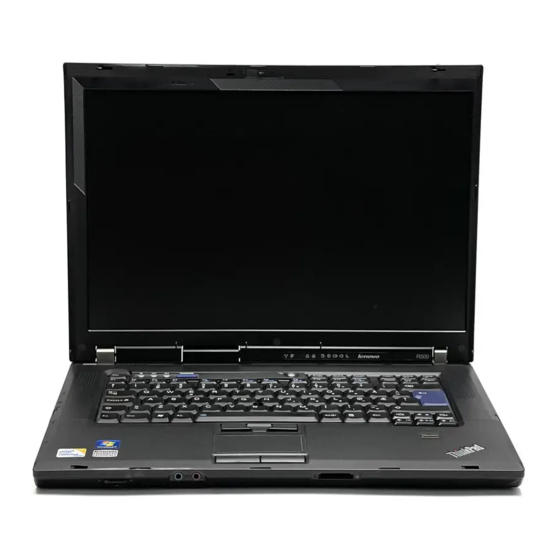
Page 145: Locations
Locations This chapter presents the location of ThinkPad R500 features and hardware. Front view ThinkLight Integrated camera (for some models) Status indicators Note: For the description of each indicator, see “Status indicators” on page 71. Wireless LAN antennas Stereo speakers... -
Page 146: Rear View
Note: For the description of each indicator, see “Status indicators” on page IEEE 1394 connector PC Card/ExpressCard/Smart Card slots eject buttons PC Card/ExpressCard/Smart Card slots USB connector RJ-45 (Ethernet) connector Display Port External monitor connector AC power connector RJ-11 (modem) connector ThinkPad R500 Hardware Maintenance Manual... -
Page 147: Bottom View
Bottom view Battery pack Battery pack latch Docking connector Wireless radio switch Stereo headphone jack Microphone jack 7-in-1 Media Card Reader slot LCD cover latch Hard disk drive Locations... - Page 148 ThinkPad R500 Hardware Maintenance Manual...
-
Page 149: Parts List
CRU. A single asterisk (*) means that the part is a Self-service CRU; two asterisks (**) means that the part is an Optional-service CRU. ThinkPad computers contain the following types of CRUs: Self-service CRUs These CRUs unplug or are held by no more than two screws. -
Page 150: Overall
Overall ThinkPad R500 Hardware Maintenance Manual... - Page 151 Table 31. Parts list—Overall FRU no. a - g See “Miscellaneous parts” on page 192. LCD unit (see “LCD FRUs” on page 179.) Keyboard bezel 44C9571 Palm rest assembly with fingerprint reader 45N5628 v 2713-CTO, 3Jx, 5Kx, 5Lx, 5Mx, 7Bx v 2714-CTO, 34x, 38x, 39x, 3Bx, 3Cx, 3Dx, 3Ex, 4Mx, 4Nx, 4Px, 4Qx, 4Rx, 4Sx, 4Tx, 4Ux, 4Vx, 4Wx, 4Xx, 4Yx, 4Zx, 53x, 54x, 5Ux, 5Yx, 5Zx, 62x, 63x, 64x, 65x, 66x, 67x, 6Ax, 6Cx, 6Dx, 6Ex, 6Fx, 77x, 79x, 7Jx, 7Kx, 7Lx, 7Mx, 7Nx, 7Tx, 7Ux, 7Vx, 7Wx, 7Xx, 7Yx,...
- Page 152 Table 31. Parts list—Overall (continued) FRU no. ThinkPad 11b/g Wireless LAN Mini PCI Express Adapter III 43Y6511 v 2713-CTO, 5Jx, 99x v 2714-CTO, 54x, 59x, 5Ax, 5Bx, 5Cx v 2716-CTO, 5Tx, 9Ax v 2717-CTO v 2718-CTO v 2719-CTO v 2720-CTO...
- Page 153 2733-CTO v 2734-CTO v 2735-CTO v 2736-CTO v 2737-CTO ThinkPad 11b/g/n Wireless LAN Mini-PCI Express Adapter II 43Y6553 v 2713-CTO, 9Dx v 2714-CTO, 9Rx, A7x, AFx, ARx, B8x v 2716-CTO, 9Ex, 9Fx, 9Gx, 9Hx, 9Jx, 9Kx, 9Lx, 9Mx, A5x...
- Page 154 Table 31. Parts list—Overall (continued) FRU no. ThinkPad 11b/g/n Wireless LAN Mini-PCI Express Adapter II 60Y3177 v 2713-CTO, 9Dx v 2714-CTO, 9Rx, A7x, AFx, ARx, B8x v 2716-CTO, 9Ex, 9Fx, 9Gx, 9Hx, 9Jx, 9Kx, 9Lx, 9Mx, A5x v 2717-CTO, A8x, ASx...
- Page 155 Table 31. Parts list—Overall (continued) FRU no. SATA hard disk drive, 80 GB, 5,400 rpm 42T1305 v 2713-CTO, 3Hx, 7Ax v 2714-CTO, 4Wx, 4Xx, 53x, 7Px, E2x, E7x, E8x, E9x, EAx v 2716-CTO, 3Kx, 3Tx, 5Px, 6Jx, 6Lx, 7Cx, 7Gx, 7Hx, ECx v 2717-CTO v 2718-CTO, 3Kx, 49x, 6Lx v 2719-CTO...
- Page 156 4Jx, 4Lx, 4Mx, 4Xx, 4Yx, 4Zx, 53x, 55x, 57x, 59x, 5Tx, 5Vx, 5Wx, 5Yx, 5Zx, 62x, 6Bx, v 2733-CTO, 3Bx, 3Cx, 3Dx, 3Ex, 3Fx, 3Gx, 4Tx, 5Hx, 5Jx, 65x, 66x, 67x, 68x, 6Nx, 6Px, 6Qx, 6Rx, 7Bx, 7Cx, 7Dx, 7Mx, 7Nx, 7Px, 7Qx v 2734-CTO v 2735-CTO v 2736-CTO v 2737-CTO ThinkPad R500 Hardware Maintenance Manual...
- Page 157 Table 31. Parts list—Overall (continued) FRU no. SATA hard disk drive, 250 GB, 5,400 rpm OP 42T1481 v 2713-CTO, 3Gx, 5Mx v 2714-CTO, 3Bx, 4Qx, 4Ux, 4Vx, 64x, 6Ax, 6Cx, 6Dx, 6Ex, 6Hx, 7Lx, 7Mx, 7Tx, 7Ux, 7Vx, 7Wx, 7Xx, 8Lx, 8Tx, 8Ux, 96x, 9Nx, 9Px, 9Qx, 9Rx, 9Sx, 9Tx, 9Ux, 9Vx, 9Wx, 9Xx, A7x, A9x, AAx, AFx, AGx, AHx, AJx, AKx, ALx, AMx, ANx, B6x, B7x v 2716-CTO, 3Zx, 45x, 6Qx, 83x, 8Dx, 8Px, 8Zx, 9Hx, A2x, AXx, AYx, AZx, B4x v 2717-CTO, 8Vx, 9Yx, ATx...
- Page 158 SATA hard disk drive, 500 GB, 5,400 rpm 45N7211 v 2713-CTO, 99x v 2714-CTO v 2716-CTO, 9Ax v 2717-CTO v 2718-CTO v 2719-CTO v 2720-CTO v 2731-CTO, 77x v 2732-CTO v 2733-CTO, 78x v 2734-CTO v 2735-CTO v 2736-CTO v 2737-CTO ThinkPad R500 Hardware Maintenance Manual...
- Page 159 Table 31. Parts list—Overall (continued) FRU no. SATA hard disk drive, 500 GB, 5,400 rpm 45N7221 v 2713-CTO, 99x v 2714-CTO v 2716-CTO, 9Ax v 2717-CTO v 2718-CTO v 2719-CTO v 2720-CTO v 2731-CTO, 77x v 2732-CTO v 2733-CTO, 78x v 2734-CTO v 2735-CTO v 2736-CTO...
- Page 160 2718-CTO, 4Bx, 4Hx, 6Vx, 73x, 8Sx v 2719-CTO v 2720-CTO v 2731-CTO, 37x v 2732-CTO v 2733-CTO, 3Jx, 3Mx, 3Nx, 5Lx, 5Nx, 5Px, 6Cx, 6Tx, 7Sx, 7Tx v 2734-CTO v 2735-CTO, 3Sx, 5Rx v 2736-CTO v 2737-CTO ThinkPad R500 Hardware Maintenance Manual...
- Page 161 Table 31. Parts list—Overall (continued) FRU no. SATA hard disk drive, 200 GB , FDE, 7,200 rpm OP 42T1463 v 2713-CTO v 2714-CTO v 2716-CTO v 2717-CTO v 2718-CTO, 4Gx, 4Jx, 72x, 74x v 2719-CTO v 2720-CTO v 2731-CTO v 2732-CTO v 2733-CTO, 3Kx, 3Px v 2734-CTO v 2735-CTO, 3Tx, 3Ux, 5Sx...
- Page 162 2713-CTO v 2714-CTO, 8Mx v 2716-CTO, 8Bx v 2717-CTO v 2718-CTO, 8Gx v 2719-CTO v 2720-CTO v 2731-CTO v 2732-CTO, 6Lx v 2733-CTO, 6Vx, 6Wx v 2734-CTO v 2735-CTO, 72x v 2736-CTO v 2737-CTO ThinkPad R500 Hardware Maintenance Manual...
- Page 163 Table 31. Parts list—Overall (continued) FRU no. SATA hard disk drive, 500 GB, 7,200 rpm 45N7267 v 2713-CTO v 2714-CTO v 2716-CTO v 2717-CTO v 2718-CTO v 2719-CTO v 2720-CTO v 2731-CTO v 2732-CTO v 2733-CTO v 2734-CTO v 2735-CTO v 2736-CTO v 2737-CTO Battery pack, Li-ion (6 cell, 2.2 Ah)
- Page 164 6Sx, 6Tx, 6Ux, 6Vx, 6Wx, 78x, 7Bx, 7Cx, 7Dx, 7Mx, 7Nx, 7Px, 7Qx, 7Rx, 7Sx, 7Tx, 7Wx, 7Xx, 7Zx, 82x v 2734-CTO, 7Lx, 7Vx v 2735-CTO, 3Rx, 3Sx, 3Tx, 3Ux, 3Vx, 5Qx, 5Rx, 5Sx, 6Zx, 72x v 2736-CTO v 2737-CTO ThinkPad R500 Hardware Maintenance Manual...
- Page 165 Table 31. Parts list—Overall (continued) FRU no. Battery pack, Li-ion (6 cell, 2.4 Ah) 42T4670 v 2713-CTO, 3Fx, 3Gx, 3Hx, 3Jx, 5Jx, 5Kx, 5Lx, 5Mx, 7Ax, 7Bx, 97x, 98x, 99x, 9Dx v 2714-CTO, 34x, 36x, 37x, 38x, 39x, 3Ax, 3Bx, 3Cx, 3Dx, 3Ex, 4Lx, 4Mx, 4Nx, 4Px, 4Qx, 4Rx, 4Sx, 4Tx, 4Ux, 4Vx, 4Wx, 4Xx, 4Yx, 4Zx, 53x, 54x, 55x, 56x, 57x, 58x, 59x, 5Ax, 5Bx, 5Cx, 5Dx, 5Ux, 5Vx, 5Wx, 5Xx, 5Yx, 5Zx, 62x, 63x, 64x, 65x, 66x, 67x, 68x, 69x, 6Ax, 6Bx, 6Cx, 6Dx, 6Ex, 6Fx, 6Gx, 6Hx, 76x, 77x, 78x, 79x, 7Jx, 7Kx, 7Lx, 7Mx, 7Nx,...
- Page 166 Battery pack, Li-ion (6 cell, 2.6 Ah) 42T4622 v 2713-CTO v 2714-CTO v 2716-CTO v 2717-CTO v 2718-CTO v 2719-CTO v 2720-CTO v 2731-CTO v 2732-CTO v 2733-CTO v 2734-CTO v 2735-CTO v 2736-CTO v 2737-CTO ThinkPad R500 Hardware Maintenance Manual...
- Page 167 Table 31. Parts list—Overall (continued) FRU no. Battery pack, Li-ion (6 cell, 2.6 Ah) 42T4621 v 2713-CTO v 2714-CTO v 2716-CTO v 2717-CTO v 2718-CTO v 2719-CTO v 2720-CTO v 2731-CTO v 2732-CTO v 2733-CTO v 2734-CTO v 2735-CTO v 2736-CTO v 2737-CTO Battery pack, Li-ion (6 cell, 2.6 Ah) 42T4623...
- Page 168 2736-CTO v 2737-CTO DVD drive 42T2561 v 2713-CTO, 97x v 2714-CTO v 2716-CTO v 2717-CTO v 2718-CTO v 2719-CTO v 2720-CTO v 2731-CTO v 2732-CTO v 2733-CTO v 2734-CTO v 2735-CTO v 2736-CTO v 2737-CTO ThinkPad R500 Hardware Maintenance Manual...
- Page 169 Table 31. Parts list—Overall (continued) FRU no. DVD/CD-RW combo drive 42T2535 v 2713-CTO, 3Hx, 7Ax, 98x, 9Dx v 2714-CTO, 4Sx, 4Wx, 4Xx, 53x, 55x, 57x, 66x, 7Px, 92x, 94x, E2x, E5x, E6x, E7x, E8x v 2716-CTO, 3Kx, 3Tx, 5Px, 6Jx, 7Cx, 7Gx, 8Yx, ECx v 2717-CTO v 2718-CTO, 3Kx, 49x v 2719-CTO...
- Page 170 6Sx, 6Tx, 6Ux, 6Vx, 6Wx, 78x, 7Bx, 7Cx, 7Dx, 7Mx, 7Nx, 7Px, 7Qx, 7Rx, 7Sx, 7Tx, 7Wx, 7Xx, 7Zx, 82x v 2734-CTO, 7Lx, 7Vx v 2735-CTO, 3Rx, 3Sx, 3Tx, 3Ux, 5Qx, 5Rx, 5Sx, 6Zx, 72x v 2736-CTO v 2737-CTO ThinkPad R500 Hardware Maintenance Manual...
- Page 171 Table 31. Parts list—Overall (continued) FRU no. DVD-RAM/RW drive 42T2565 v 2713-CTO, 3Fx, 3Gx, 3Jx, 5Jx, 5Kx, 5Lx, 5Mx, 7Bx, 99x v 2714-CTO, 34x, 37x, 38x, 39x, 3Ax, 3Bx, 3Cx, 3Dx, 3Ex, 4Lx, 4Mx, 4Nx, 4Px, 4Qx, 4Rx, 4Tx, 4Ux, 4Vx, 4Yx, 4Zx, 54x, 56x, 58x, 59x, 5Ax, 5Bx, 5Cx, 5Dx, 5Ux, 5Wx, 5Xx, 5Yx, 5Zx, 62x, 63x, 64x, 65x, 67x, 69x, 6Ax, 6Bx, 6Cx, 6Dx, 6Ex, 6Fx, 6Gx, 6Hx, 76x, 77x, 78x, 79x, 7Jx, 7Kx, 7Lx, 7Mx, 7Nx, 7Qx, 7Sx, 7Tx, 7Ux, 7Vx, 7Wx, 7Xx, 7Yx, 8Lx, 8Mx, 8Tx, 8Ux, 93x, 95x, 96x, 9Nx, 9Px, 9Qx, 9Rx, 9Sx, 9Tx, 9Ux, 9Vx, 9Wx, 9Xx, A7x, A9x, AAx,...
- Page 172 6Sx, 6Tx, 6Ux, 6Vx, 6Wx, 78x, 7Bx, 7Cx, 7Dx, 7Mx, 7Nx, 7Px, 7Qx, 7Rx, 7Sx, 7Tx, 7Wx, 7Xx, 7Zx, 82x v 2734-CTO, 7Lx, 7Vx v 2735-CTO, 3Rx, 3Sx, 3Tx, 3Ux, 5Qx, 5Rx, 5Sx, 6Zx, 72x v 2736-CTO v 2737-CTO ThinkPad R500 Hardware Maintenance Manual...
- Page 173 Table 31. Parts list—Overall (continued) FRU no. DVD-RAM/RW drive 42T2573 v 2713-CTO, 3Fx, 3Gx, 3Jx, 5Jx, 5Kx, 5Lx, 5Mx, 7Bx, 99x v 2714-CTO, 34x, 37x, 38x, 39x, 3Ax, 3Bx, 3Cx, 3Dx, 3Ex, 4Lx, 4Mx, 4Nx, 4Px, 4Qx, 4Rx, 4Tx, 4Ux, 4Vx, 4Yx, 4Zx, 54x, 56x, 58x, 59x, 5Ax, 5Bx, 5Cx, 5Dx, 5Ux, 5Wx, 5Xx, 5Yx, 5Zx, 62x, 63x, 64x, 65x, 67x, 69x, 6Ax, 6Bx, 6Cx, 6Dx, 6Ex, 6Fx, 6Gx, 6Hx, 76x, 77x, 78x, 79x, 7Jx, 7Kx, 7Lx, 7Mx, 7Nx, 7Qx, 7Sx, 7Tx, 7Ux, 7Vx, 7Wx, 7Xx, 7Yx, 8Lx, 8Mx, 8Tx, 8Ux, 93x, 95x, 96x, 9Nx, 9Px, 9Qx, 9Rx, 9Sx, 9Tx, 9Ux, 9Vx, 9Wx, 9Xx, A7x, A9x, AAx,...
- Page 174 Base cover assembly for 2733 (World-wide) 45M2554 Base cover assembly for 2734 (World-wide) 45M2555 Base cover assembly for 2735 (World-wide) 45M2556 Base cover assembly for 2736 (World-wide) 45M2557 Base cover assembly for 2737 (World-wide) 45M2558 ThinkPad R500 Hardware Maintenance Manual...
- Page 175 Table 31. Parts list—Overall (continued) FRU no. PC Card/ExpressCard bezel assembly 42X3917 v 2713-CTO, 3Fx, 3Hx, 3Jx, 5Jx, 5Kx, 5Lx, 5Mx, 7Ax, 7Bx, 97x, 98x, 99x, 9Dx v 2714-CTO, 34x, 36x, 37x, 38x, 39x, 3Ax, 3Bx, 3Cx, 3Dx, 3Ex, 4Lx, 4Mx, 4Nx, 4Px, 4Qx, 4Rx, 4Sx, 4Tx, 4Ux, 4Vx, 4Wx, 4Xx, 4Yx, 4Zx, 53x, 54x, 55x, 56x, 57x, 58x, 59x, 5Ax, 5Bx, 5Cx, 5Dx, 5Ux, 5Vx, 5Wx, 5Xx, 5Yx, 5Zx, 62x, 63x, 64x, 65x, 66x, 67x, 68x, 69x, 6Ax, 6Bx, 6Cx, 6Dx, 6Ex, 6Fx, 6Gx, 6Hx, 76x, 77x, 78x, 79x, 7Jx, 7Kx, 7Lx, 7Mx, 7Nx,...
- Page 176 2733-CTO, 3Bx, 3Dx, 3Ex, 3Fx, 3Gx, 3Hx, 3Jx, 3Kx, 4Tx, 4Ux, 5Hx, 5Jx, 5Kx, 5Lx, 65x, 66x, 67x, 68x, 6Cx, 6Tx, 6Vx, 6Wx, 7Sx v 2734-CTO, 7Lx v 2735-CTO, 72x v 2736-CTO v 2737-CTO ThinkPad R500 Hardware Maintenance Manual...
- Page 177 Table 31. Parts list—Overall (continued) FRU no. 2-GB DDR3-1067 SDRAM SO-DIMM (PC3-8500) card 43R1969 v 2713-CTO, 3Gx, 5Lx, 99x v 2714-CTO, 34x, 5Ux, 77x, 79x, 7Lx, 7Mx, 7Tx, 7Ux, 8Tx, 8Ux, 96x, 9Nx, 9Px, 9Qx, 9Rx, 9Sx, 9Tx, 9Ux, 9Vx, 9Wx, 9Xx, A7x, A9x, AAx, AFx, AGx, AHx, AJx, AKx, ALx, AMx, ANx, B5x, B6x, B7x, B8x v 2716-CTO, 3Sx, 45x, 7Fx, 7Rx, 82x, 83x, 84x, 85x, 86x, 88x, 89x, 8Ax, 8Bx, 8Cx, 8Dx, 8Sx, 8Zx, 9Ax, 9Ex, 9Fx, 9Gx, 9Hx, 9Jx, 9Lx, 9Mx, 9Zx, A2x, A3x, A4x, A6x, ADx, AEx, AUx,...
- Page 178 2714-CTO, 7Px, 7Qx, E2x, E3x, E4x, E5x, E6x, E7x, E8x, E9x, EAx v 2716-CTO, EBx, ECx v 2717-CTO v 2718-CTO v 2719-CTO v 2720-CTO CPU assembly, Intel Celeron processor585 (2.16 GHz) 42W8033 v 2713-CTO v 2714-CTO v 2716-CTO v 2717-CTO v 2718-CTO v 2719-CTO v 2720-CTO ThinkPad R500 Hardware Maintenance Manual...
- Page 179 Table 31. Parts list—Overall (continued) FRU no. CPU assembly, Intel Celeron processor900 (2.2 GHz) 43R0795 v 2713-CTO, 97x, 98x v 2714-CTO, 92x, 93x, 94x, 95x, ARx v 2716-CTO, A5x v 2717-CTO v 2718-CTO, 9Bx, 9Cx v 2719-CTO v 2720-CTO CPU assembly, Intel Celeron processor T3000 (1.8 GHz) 43R0894 v 2713-CTO v 2714-CTO...
- Page 180 2717-CTO, 9Yx, ABx, ACx, ATx v 2718-CTO v 2719-CTO v 2720-CTO v 2731-CTO v 2732-CTO, 75x, 76x, 7Jx, 7Kx, 7Ux v 2733-CTO, 6Nx, 6Px, 6Tx, 7Bx, 7Cx, 7Zx, 82x v 2734-CTO, 7Vx v 2735-CTO v 2736-CTO v 2737-CTO ThinkPad R500 Hardware Maintenance Manual...
- Page 181 Table 31. Parts list—Overall (continued) FRU no. CPU assembly, Intel Core 2 Duo mobile processor P8800 (2.66 GHz) 45M2814 v 2713-CTO v 2714-CTO, AKx, ALx v 2716-CTO, 9Zx, A2x, A3x, A6x, ADx, AEx v 2717-CTO v 2718-CTO v 2719-CTO v 2720-CTO v 2731-CTO v 2732-CTO, 7Yx v 2733-CTO, 7Mx, 7Nx, 7Sx, 7Tx, 7Wx...
- Page 182 2718-CTO, 3Lx, 3Mx, 4Hx, 4Jx, 4Kx, 73x, 74x v 2719-CTO v 2720-CTO v 2731-CTO, 38x, 4Rx v 2732-CTO v 2733-CTO, 3Fx, 3Gx, 3Nx, 3Px, 3Qx, 5Jx, 5Px, 66x, 68x v 2734-CTO v 2735-CTO, 3Tx, 3Ux, 3Vx, 5Sx v 2736-CTO v 2737-CTO ThinkPad R500 Hardware Maintenance Manual...
- Page 183 Table 31. Parts list—Overall (continued) FRU no. CPU assembly, Intel Core 2 Duo mobile processor T9550 (2.66 GHz) 42W8195 v 2713-CTO v 2714-CTO v 2716-CTO, 85x, 86x, 8Ax v 2717-CTO v 2718-CTO, 8Fx v 2719-CTO v 2720-CTO v 2731-CTO v 2732-CTO v 2733-CTO, 6Qx, 6Rx, 6Sx, 6Ux, 7Dx v 2734-CTO v 2735-CTO, 6Zx...
- Page 184 6Vx, 6Wx, 78x, 7Bx, 7Cx, 7Dx, 7Mx, 7Nx, 7Px, 7Qx, 7Rx, 7Sx, 7Tx, 7Wx, 7Xx, 7Zx, 82x v 2734-CTO, 7Lx, 7Vx v 2735-CTO, 3Rx, 3Sx, 3Tx, 3Ux, 5Qx, 5Rx, 5Sx, 6Zx, 72x v 2736-CTO v 2737-CTO ThinkPad R500 Hardware Maintenance Manual...
- Page 185 Table 31. Parts list—Overall (continued) FRU no. ExpressCard/Smart Card slot 42X4992 v 2713-CTO, 3Gx v 2714-CTO v 2716-CTO, 3Xx, 6Px v 2717-CTO v 2718-CTO, 4Dx, 6Xx v 2719-CTO v 2720-CTO v 2731-CTO, 38x v 2732-CTO v 2733-CTO, 3Jx, 3Qx, 5Lx v 2734-CTO v 2735-CTO, 3Vx v 2736-CTO...
- Page 186 2734-all v 2735-all v 2736-CTO v 2737-CTO Keyboard (see “Keyboard” on page 190.) TrackPoint stick caps 91P9642 — Thermal grease 91P8835 — Telephone cable 91P6967 — AC adapter (see “AC adapters” on page 194.) ThinkPad R500 Hardware Maintenance Manual...
-
Page 187: Lcd Frus
LCD FRUs In R500, there are following types of LCDs. v 15.4-in. WXGA TFT LCD (Table 32 on page 180) v 15.4-in. WSXGA+ TFT LCD (Table 33 on page 188) Parts list... - Page 188 2733-CTO, 3Bx, 3Cx, 3Dx, 3Fx, 4Tx, 4Ux, 5Hx, 65x, 67x, 6Nx, 6Qx, 6Ux, 6Wx, 7Bx, 7Cx, 7Mx, 7Px, 7Tx, 7Zx, 82x v 2734-CTO, 7Lx v 2735-CTO, 6Zx, 72x v 2736-CTO v 2737-CTO Hinges 44C0930 Hinges 44C0931 ThinkPad R500 Hardware Maintenance Manual...
- Page 189 Table 32. Parts list—15.4-in. WXGA TFT (continued) FRU no. Integrated camera 42T3108 v 2713-CTO, 3Fx, 3Gx, 99x v 2714-CTO, 36x, 37x, 38x, 3Ax, 3Bx, 3Dx, 3Ex, 54x, 5Vx, 5Wx, 5Xx, 5Yx, 5Zx, 68x, 69x, 6Ax, 6Ex, 7Nx, 7Tx, 7Ux, 8Tx, 8Ux, 96x, 9Nx, 9Sx, 9Tx, 9Vx, 9Wx, 9Xx, A7x, A9x, AAx, AFx, AGx, AHx, AJx, AKx, ALx, B5x, B6x, B7x v 2716-CTO, 3Mx, 5Nx, 5Px, 5Qx, 87x, 88x, 8Ex, 8Sx, 8Yx, 8Zx, 9Ax, 9Kx, 9Lx, AUx, AVx, B4x, EBx, ECx...
- Page 190 2736-CTO v 2737-CTO LED control card 45M2778 v 2713-CTO v 2714-CTO v 2716-CTO v 2717-CTO v 2718-CTO v 2719-CTO v 2720-CTO v 2731-CTO v 2732-CTO v 2733-CTO v 2734-CTO v 2735-CTO v 2736-CTO v 2737-CTO ThinkPad R500 Hardware Maintenance Manual...
- Page 191 Table 32. Parts list—15.4-in. WXGA TFT (continued) FRU no. LED control card 45M2780 v 2713-CTO v 2714-CTO v 2716-CTO v 2717-CTO v 2718-CTO v 2719-CTO v 2720-CTO v 2731-CTO v 2732-CTO v 2733-CTO v 2734-CTO v 2735-CTO v 2736-CTO v 2737-CTO Bluetooth daughter card (BDC-2.1) 42T0969 v 2713-CTO, 3Fx, 3Gx, 3Jx, 5Jx, 5Kx, 5Lx, 5Mx, 7Bx, 99x...
- Page 192 5Ax, 5Wx, 5Zx, 6Dx, 6Lx, 75x, 76x, 7Ex, 7Fx, 7Gx, 7Hx, 7Yx, 84x v 2733-CTO, 3Bx, 3Cx, 3Dx, 3Fx, 4Tx, 4Ux, 5Hx, 65x, 67x, 6Nx, 6Qx, 6Ux, 6Wx, 7Bx, 7Cx, 7Mx, 7Px, 7Tx, 7Zx, 82x v 2734-CTO, 7Lx v 2735-CTO, 6Zx, 72x v 2736-CTO v 2737-CTO ThinkPad R500 Hardware Maintenance Manual...
- Page 193 Table 32. Parts list—15.4-in. WXGA TFT (continued) FRU no. LCD panel, 15.4-in. WXGA 42T0484 v 2713-CTO, 3Fx, 3Gx, 3Hx, 3Jx, 5Jx, 5Kx, 5Lx, 5Mx, 7Ax, 7Bx, 97x, 98x, 99x, 9Dx v 2714-CTO, 34x, 36x, 37x, 38x, 39x, 3Ax, 3Bx, 3Cx, 3Dx, 3Ex, 4Lx, 4Mx, 4Nx, 4Px, 4Qx, 4Rx, 4Sx, 4Tx, 4Ux, 4Vx, 4Wx, 4Xx, 4Yx, 4Zx, 53x, 54x, 55x, 56x, 57x, 58x, 59x, 5Ax, 5Bx, 5Cx, 5Dx, 5Ux, 5Vx, 5Wx, 5Xx, 5Yx, 5Zx, 62x, 63x, 64x, 65x, 66x, 67x, 68x, 69x, 6Ax, 6Bx, 6Cx, 6Dx, 6Ex, 6Gx, 6Hx, 76x, 77x, 78x, 79x, 7Jx, 7Kx, 7Lx, 7Mx, 7Nx, 7Px,...
- Page 194 5Ax, 5Wx, 5Zx, 6Dx, 6Lx, 75x, 76x, 7Ex, 7Fx, 7Gx, 7Hx, 7Yx, 84x v 2733-CTO, 3Bx, 3Cx, 3Dx, 3Fx, 4Tx, 4Ux, 5Hx, 65x, 67x, 6Nx, 6Qx, 6Ux, 6Wx, 7Bx, 7Cx, 7Mx, 7Px, 7Tx, 7Zx, 82x v 2734-CTO, 7Lx v 2735-CTO, 6Zx, 72x v 2736-CTO v 2737-CTO ThinkPad R500 Hardware Maintenance Manual...
- Page 195 Table 32. Parts list—15.4-in. WXGA TFT (continued) FRU no. LCD panel, 15.4-in. WXGA 42T0576 v 2713-CTO, 3Fx, 3Gx, 3Hx, 3Jx, 5Jx, 5Kx, 5Lx, 5Mx, 7Ax, 7Bx, 97x, 98x, 99x, 9Dx v 2714-CTO, 34x, 36x, 37x, 38x, 39x, 3Ax, 3Bx, 3Cx, 3Dx, 3Ex, 4Lx, 4Mx, 4Nx, 4Px, 4Qx, 4Rx, 4Sx, 4Tx, 4Ux, 4Vx, 4Wx, 4Xx, 4Yx, 4Zx, 53x, 54x, 55x, 56x, 57x, 58x, 59x, 5Ax, 5Bx, 5Cx, 5Dx, 5Ux, 5Vx, 5Wx, 5Xx, 5Yx, 5Zx, 62x, 63x, 64x, 65x, 66x, 67x, 68x, 69x, 6Ax, 6Bx, 6Cx, 6Dx, 6Ex, 6Gx, 6Hx, 76x, 77x, 78x, 79x, 7Jx, 7Kx, 7Lx, 7Mx, 7Nx, 7Px,...
- Page 196 2733-CTO, 3Gx, 3Jx, 3Kx, 3Px, 3Qx, 5Jx, 5Lx, 66x, 68x, 6Cx, 6Rx, 6Sx, 6Tx, 6Vx, 78x, 7Qx, 7Rx, 7Sx v 2734-CTO v 2735-CTO, 3Ux, 3Vx v 2736-CTO v 2737-CTO Inverter card 41W1482 Inverter card 41W1484 ThinkPad R500 Hardware Maintenance Manual...
- Page 197 Table 33. Parts list—15.4-in. WSXGA+ TFT (continued) FRU no. Bluetooth daughter card (BDC-2.1) 42T0969 v 2713-CTO v 2714-CTO, 6Fx v 2716-CTO, 3Qx, 3Sx, 7Fx, 84x, 86x, 8Ax, 9Jx, A3x, A4x, AEx v 2717-CTO v 2718-CTO, 4Fx, 4Gx, 4Hx, 4Jx, 4Kx, 6Zx, 72x, 73x, 74x v 2719-CTO v 2720-CTO v 2731-CTO, 37x, 38x, 3Ax, 4Qx, 4Rx, 4Sx, 64x, 77x, 7Ax...
-
Page 198: Keyboard
42T4088 42T3959 Thai 42T4030 42T4094 42T3965 Traditional Chinese 42T4029 42T4093 42T3964 Turkish 42T4025 42T4089 42T3960 U.K. English 42T4026 42T4090 42T3961 U.S. English 42T4002 42T4066 42T3937 U.S. English (International, with a Euro symbol) 42T4027 42T4091 42T3962 ThinkPad R500 Hardware Maintenance Manual... - Page 199 Table 35. Parts list—Keyboard Language Arabic 42T3212 42T3276 42T3146 Belgian 42T3213 42T3277 42T3147 Brazilian Portuguese 42T3240 42T3304 42T3174 Canadian French (058) 42T3211 42T3275 42T3145 Canadian French (Acnor) 42T3210 42T3274 42T3144 Czech 42T3214 42T3278 42T3148 Danish 42T3215 42T3279 42T3149 Dutch 42T3223 42T3287 42T3157 Finnish, Swedish...
-
Page 200: Miscellaneous Parts
(d) Bracket, Kensington v (e) Bracket, CPU support v (f) Bracket, N/B, fan discrete/integ. v (g) Bracket, VGA, fan discrete/integ. Note: Italicized letters in parentheses are references to the exploded view in “Overall” on page 142. ThinkPad R500 Hardware Maintenance Manual... - Page 201 Table 36. Parts list—Miscellaneous parts (continued) System board miscellaneous parts: 44C9563 N v Insulation sheet, battery connector v Insulation sheet, docking v Insulation sheet, front louver v Insulation sheet, PC Card slot v Insulation sheet, 7-in-1 media reader slot v Insulation sheet, front top v Insulation sheet, NB v Insulation sheet, Video v Label, AMoM...
-
Page 202: Ac Adapters
3-pin (65 W, 20 V) adapter (models CTO, xxA, xxB, xxC, xxG, xxH, xxK, xxM, xxT, xxV) 42T4417 3-pin (65 W, 20 V) adapter (models CTO, xxA, xxB, xxC, xxG, xxH, xxK, xxM, xxT, xxV) 42T4421 ThinkPad R500 Hardware Maintenance Manual... -
Page 203: Power Cords
Power cords A ThinkPad power cord for a specific country or region is usually available only in that country or region: Table 39. Parts list—2-pin power cords Country or region FRU no. Argentina 42T5020 42T5105 * v models -CTO, xxY... -
Page 204: Recovery Discs
5Dx, 5Ex, 5Fx, 5Gx, 62x, 6Ax, 6Fx, 76x, 7Gx, 7Jx, 7Yx v 2733-CTO, 5Hx, 5Jx, 5Kx, 5Lx, 5Mx, 5Nx, 5Px, 67x, 68x, 78x, 7Bx, 7Zx v 2734-CTO, 7Lx v 2735-CTO, 5Qx, 5Rx, 5Sx v 2736-CTO v 2737-CTO ThinkPad R500 Hardware Maintenance Manual... - Page 205 Table 41. Parts list—Windows XP Professional (32 bit) recovery DVDs Language Arabic 58Y1832 Brazilian Portuguese 58Y1833 Czech 58Y1836 Danish 58Y1837 Dutch 58Y1848 English 58Y1858 English (modem-disabled) 58Y1857 Finnish 58Y1838 French 58Y1839 German 58Y1841 Greek 58Y1840 Hebrew 58Y1842 Hungarian 58Y1844 Italian 58Y1845 Japanese 58Y2622...
-
Page 206: Windows Vista Starter Edition (32 Bit) Recovery Dvds
2718-CTO v 2719-CTO v 2720-CTO v 2731-CTO v 2732-CTO v 2733-CTO v 2734-CTO v 2735-CTO v 2736-CTO v 2737-CTO Table 42. Parts list—Windows Vista Starter Edition (32 bit) recovery DVDs Language English (for India) 58Y2097 ThinkPad R500 Hardware Maintenance Manual... -
Page 207: Windows Vista Home Basic (32 Bit) Recovery Dvds
Windows Vista Home Basic (32 bit) recovery DVDs Windows Vista Home Basic (32 bit) is preinstalled as the operating system in the following models: v 2713-CTO, 5Jx, 99x v 2714-CTO, 54x, 5Cx, E7x, E8x, 9Rx, 9Ux v 2716-CTO, 5Tx, 9Ax v 2717-CTO v 2718-CTO, 49x, 4Ax v 2719-CTO... - Page 208 58Y2029 Italian 58Y2030 Japanese 58Y2627 Korean 58Y2032 Norwegian 58Y2033 Polish 58Y2034 Romanian 58Y2035 Serbian-Latin 58Y2039 Simplified Chinese 58Y2020 Slovak 58Y2036 Slovenian 58Y2037 Spanish 58Y2038 Traditional Chinese 58Y2021 Traditional Chinese (Hong Kong S.A.R.) 58Y2028 Turkish 58Y2040 ThinkPad R500 Hardware Maintenance Manual...
-
Page 209: Windows Vista Home Premium (32 Bit) Recovery Dvds
Windows Vista Home Premium (32 bit) recovery DVDs Windows Vista Home Premium (32 bit) is preinstalled as the operating system in the following models: v 2713-CTO v 2714-CTO, 39x, 3Bx, 3Cx, 4Wx, 4Xx, 4Yx, 4Zx, 53x, 9Nx, 9Px, 9Qx, 9Tx, E9x, EAx v 2716-CTO v 2717-CTO v 2718-CTO... -
Page 210: Windows Vista Business (32 Bit) Recovery Dvds
2733-CTO, 3Bx, 3Dx, 3Ex, 3Fx, 3Gx, 3Hx, 3Jx, 3Lx, 3Mx, 3Nx, 4Tx, 4Ux, 65x, 66x, 6Cx, 6Nx, 6Px, 6Qx, 6Rx, 6Sx, 6Tx, 6Ux, 6Vx, 6Wx, 7Cx, 7Dx, 7Mx, 7Nx, 7Px, 7Qx, 7Rx, 7Sx, 7Tx v 2734-CTO v 2735-CTO, 3Rx, 3Sx, 3Tx, 6Zx, 72x v 2736-CTO v 2737-CTO ThinkPad R500 Hardware Maintenance Manual... - Page 211 Table 45. Parts list—Windows Vista Business (32 bit) recovery DVDs Language Brazilian Portuguese 58Y1913 Czech 58Y1916 Danish 58Y1917 English 58Y1939 English (modem-disabled) 58Y1938 English (for India) 58Y2093 English, Finnish, and Swedish (in Sweden) 58Y1941 English, French, German, and Dutch (in Belgium and Luxemburg) 58Y1940 English, French, German, and Italian (in Switzerland) 58Y1942...
-
Page 212: Windows Vista Business (64 Bit) Recovery Dvds
2734-CTO v 2735-CTO v 2736-CTO v 2737-CTO Table 46. Parts list—Windows Vista Business (64 bit) recovery DVDs Language English 58Y2073 English (modem-disabled) 58Y2072 English (for India) 58Y2096 German 58Y2070 Japanese 58Y2629 Simplified Chinese 58Y2069 ThinkPad R500 Hardware Maintenance Manual... -
Page 213: Windows Vista Ultimate (32 Bit) Recovery Dvds
Windows Vista Ultimate (32 bit) recovery DVDs Windows Vista Ultimate (32 bit) is preinstalled as the operating system in the following models: v 2713-CTO v 2714-CTO, 4Ux, 4Vx, 96x v 2716-CTO, 45x, 8Sx v 2717-CTO, 8Vx v 2718-CTO, 4Kx, 8Sx v 2719-CTO v 2720-CTO v 2731-CTO... - Page 214 58Y2056 Japanese 58Y2628 Korean 58Y2088 Norwegian 58Y2057 Polish 58Y2058 Romanian 58Y2059 Russian 58T2089 Serbian-Latin 58Y2063 Simplified Chinese 58Y2046 Slovak 58Y2060 Slovenian 58Y2061 Spanish 58Y2062 Traditional Chinese 58Y2047 Traditional Chinese (Hong Kong S.A.R.) 58Y2054 Turkish 58Y2064 ThinkPad R500 Hardware Maintenance Manual...
-
Page 215: Windows 7 Home Basic (32 Bit) Dvds
Windows 7 Home Basic (32 bit) DVDs Windows 7 Home Basic (32 bit) is preinstalled as the operating system in the following models: v 2713-CTO v 2714-CTO v 2716-CTO v 2717-CTO v 2718-CTO v 2719-CTO v 2720-CTO v 2731-CTO v 2732-CTO v 2733-CTO v 2734-CTO v 2735-CTO... -
Page 216: Windows 7 Home Premium (32 Bit) Dvds
English, French, German, and Italian (in Switzerland) 58Y3235 French 58Y3220 German 58Y3221 Hebrew 58Y3222 Japanese 58Y3224 Korean 58Y3225 Polish 58Y3226 Russian 58Y3228 Russian (English-enabled) 58Y3227 Simplified Chinese 58Y3217 Spanish 58Y3229 Traditional Chinese 58Y3218 Traditional Chinese (Hong Kong S.A.R.) 58Y3223 Turkish 58Y3230 ThinkPad R500 Hardware Maintenance Manual... -
Page 217: Windows 7 Home Premium (64 Bit) Dvds
Windows 7 Home Premium (64 bit) DVDs Windows 7 Home Premium (64 bit) is preinstalled as the operating system in the following models: v 2713-CTO v 2714-CTO v 2716-CTO v 2717-CTO v 2718-CTO v 2719-CTO v 2720-CTO v 2731-CTO v 2732-CTO v 2733-CTO v 2734-CTO v 2735-CTO... -
Page 218: Windows Professional (32 Bit) Dvds
2716-CTO, ADx, AEx, AVx, AYx, B2x, B4x v 2717-CTO, ACx v 2718-CTO v 2719-CTO v 2720-CTO v 2731-CTO v 2732-CTO, 7Ux, 83x, 84x v 2733-CTO, 7Wx, 7Xx, 82x v 2734-CTO, 7Vx v 2735-CTO v 2736-CTO v 2737-CTO ThinkPad R500 Hardware Maintenance Manual... - Page 219 Table 51. Parts list—Windows 7 Professional (32 bit) DVDs Language Brazilian Portuguese 58Y3242 Czech 58Y3245 Danish 58Y3246 English 58Y3268 English (modem-disabled) 58Y3267 English (for India) 58Y4030 English, Finnish, and Swedish (in Sweden) 58Y3270 English, French, German, and Dutch (in Belgium and Luxemburg) 58Y3269 English, French, German, and Italian (in Switzerland) 58Y3271...
-
Page 220: Windows Professional (64 Bit) Dvds
English, French, German, and Italian (in Switzerland) 58Y3286 French 58Y3275 German 58Y3276 Hebrew 58Y3277 Italian 58Y3279 Japanese 58Y3280 Korean 58Y3281 Polish 58Y3282 Simplified Chinese 58Y3272 Spanish 58Y3283 Traditional Chinese 58Y3273 Traditional Chinese (Hong Kong S.A.R.) 58Y3278 Turkish 58Y3284 ThinkPad R500 Hardware Maintenance Manual... -
Page 221: Common Service Tools
USB floppy diskette drive for maintenance diskette 05K9283 USB floppy diskette drive tool kit 27L3452 Test card for integrated Smart Card 42W7820 ThinkPad Hardware Maintenance Diskette Version 1.73 or later — Note: Download the file from the following Web site: http://www.lenovo.com/ Parts list... - Page 222 ThinkPad R500 Hardware Maintenance Manual...
-
Page 223: Notices
Notices Lenovo may not offer the products, services, or features discussed in this document in all countries. Consult your local Lenovo representative for information on the products and services currently available in your area. Any reference to a Lenovo product, program, or service is not intended to state or imply that only that Lenovo product, program, or service may be used. -
Page 224: Trademarks
The following are trademarks of Intel Corporation or its subsidiaries in the United States, other countries, or both: ® Intel ® ® Intel Celeron ® Intel Core 2 Duo Other company, product, or service names may be the trademarks or service marks of others. ThinkPad R500 Hardware Maintenance Manual... - Page 226 Part Number: 43Y6631_03 (1P) P/N: 43Y6631_03 *1P43Y6631_03*...
Need help?
Do you have a question about the R500 and is the answer not in the manual?
Questions and answers