Table of Contents
Advertisement
Advertisement
Table of Contents

Related Manuals for MSI MS 6760


Summary of Contents for MSI MS 6760
- Page 1 Mainboard MS 6760 Vers.1...
- Page 2 FCC-B Radio Frequency Interference Statement This equipment has been tested and found to comply with the limits for a class B digital device, pursuant to part 15 of the FCC rules. These limits are designed to provide reasonable protection against harmful interference when the equipment is operated in a commercial environment.
- Page 3 Lithium Battery Statement CAUTION Danger of explosion if battery is incorrectly replaced. Replace only with the same or equivalent type recommended by the manufactuer. Discard used bat- teries according to the manufacturer’s instructions. ® Macrovision Statement This product incorporates copyright protection technology that is protected by method claims of certain U.S.
-
Page 4: Safety Instructions
Safety Instructions Always read the safety instructions carefully. Keep this User’s Manual for future reference. Keep this equipment away from humidity. Lay this equipment on a reliable flat surface before setting it up. The openings on the enclosure are for air convection hence protects the equipment from overheating. -
Page 5: Copyright Notice
Copyright Notice The material in this document is the intellectual property of MICRO-STAR INTERNATIONAL. We take every care in the preparation of this document, but no guarantee is given as to the correctness of its contents. Our products are under continual improvement and we reserve the right to make changes with- out notice. -
Page 6: Table Of Contents
CONTENTS System Specification ................viii Chapter 1. Introducing Mainboard............1-1 Mainboard Layout................1-2 CPU/Memory.................1-3 Introduction to DDR SDRAM..........1-3 Power Supply.................1-4 Front Panel...................1-5 IEEE 1394 Port: J1394-2............1-5 IEEE 1394 Port: J1394-1............1-6 USB Ports.................1-6 Mic-in/Head-Phone.............1-7 OPTICAL SPDIF-in..............1-7 Back Panel..................1-8 Serial Port................1-8 VGA Port................1-9 Mouse/Keyboard Connectors..........1-9 RJ45 LAN Jack..............1-10 USB Ports................1-10 OPTICAL SPDIF-out............1-10... - Page 7 Modem Module Connector: CN21......1-16 Jumper................1-17 Clear CMOS Jumper: J2..........1-17 Slots..................1-18 PCI Slot...............1-18 AGP Slot..............1-18 Chapter 2: Setting BIOS Function..........2-1 Entering Setup................2-2 Control Keys..............2-2 Getting Help..............2-3 Main Menu................2-3 Sub-Menu..............2-3 General Help<F1>............2-3 The Main Menu................2-4 Standard CMOS Features............2-6 Advanced BIOS Features............2-8 Advanced Chipset Features............2-11 Integrated Peripherals..............2-13 Power Management Setup............2-19 PNP/PCI Configurations............2-23...
-
Page 8: System Specification
System Specification - MS-6760 (Proprietary F/F), 185 x 290 mm (4 layer) CPU: - Support Socket 478 for Pentium ® 4, 2.8 GHz Chipset: - SiS 651 + SiS 962 Memory: - DDR 333 x 2, support memory up to 2.0GB On-Board Audio: - AC’97 Codec integrated in ALC 650, support 5.1 channel , SPDIF In/Out. - Page 9 On-Board Headers & Connectors - Rear Panel: Parallel Port x 1, Serial Port x 1, VGA x 1, PS/2 x 2, Mic in/Line in/ Line out x 1, USB x 2, LAN (RJ45) x 1, SPDIF/O x 1, Modem (RJ11) x 1 - Front Panel: Mic in/Headphone x 1, USB x 2, SPDIF/I x 1, 1394 x 1 (4-pin), 1394 x 1(6-pin) BIOS...
-
Page 10: Chapter 1. Introducing Mainboard
Introducing Mainboard Introducing Mainboard Introducing Mainboard Introducing Mainboard Introducing Mainboard Introducing Mainboard 1.1 Mainboard Layout 1.1 Mainboard Layout 1.1 Mainboard Layout 1.1 Mainboard Layout 1.1 Mainboard Layout 1.2 CPU/Memory 1.2 CPU/Memory 1.2 CPU/Memory 1.2 CPU/Memory 1.2 CPU/Memory 1.3 Power Supply 1.3 Power Supply 1.3 Power Supply 1.3 Power Supply... -
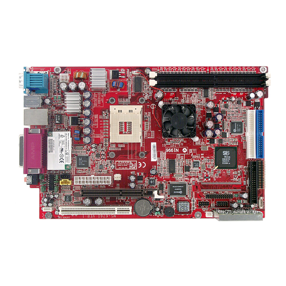
Page 11: Mainboard Layout
Chapter 1 1.1 Mainboard layout See the following for the mainboard layout: FDD Connector IDE Connectors Front Panel Connector USB Card Reader DDR DIMM Slots Connector Radio Module USB Connector Radio Antenna Connector LCM Connector Front Panel Power Connector AGP Slot Clear CMOS Jumper CPU Fan... -
Page 12: Cpu/Memory
Introducing Mainboard 1.2 CPU/memory ® ® The mainboard supports Intel Pentium 4 processors in the 478-pin package. The mainboard uses a CPU socket called PGA478 for easy CPU installation. When you are installing the CPU, make sure the CPU has a heat sink and a cooling fan attached on the top to prevent overheating. -
Page 13: Power Supply
Chapter 1 1.3 Power Supply The system is equipped with a 200W(PFC) ATX power supply. The power cord of power supply has been connected to the connectors on the mainboard when shipped out. You can find two connectors (20-Piin & CN 20) on the mainboard. -
Page 14: Front Panel
Introducing Mainboard 1.4 Front panel The Front Panel is independent and extended from the mainboard. It’s connected to the Front Panel Connector on the mainboard. You can find the following ports on the Front Panel. Optical SPDIF-In USB x 2 J1394-1 J1394-2 Mic-In Head-Phone... -
Page 15: Ieee 1394 Port: J1394-1
Chapter 1 IEEE 1394 Port: J1394-1 The bigger 6-pin IEEE 1394 Port on the back panel is designed for you to connect to IEEE 1394 devices without external power. That means the mainboard can provide the power for the devices connected to this port. Software Support IEEE 1394 Driver is provided by Windows ®... -
Page 16: Mic-In/Head-Phone
Introducing Mainboard Mic-in/Head-Phone Mic-in is a connector for microphone. Head-Phone is a connector for Speakers or Headphones. OPTICAL SPDIF-in The OPTICAL connector allows you to receive the audio file of SPDIF interface for recording and playing. The SPDIF (Sony & Philips Digital Interface) is developed jointly by the Sony and Philips corporations . -
Page 17: Back Panel
Chapter 1 1.5 Back panel The Back Panel provides the following ports: Serial Port Mouse LAN Port Parallel Port VGA Port Keyboard USB x 2 Optical SPDIF-out Lin-in Mic-in Speak-out Serial Port The mainboard offers a 9-pin male DIN serial port . The port is 16550A high speed communication ports that sends/receives 16 bytes FIFOs. -
Page 18: Vga Port
Introducing Mainboard VGA Port The mainboard provides one DB 15-pin female connector to connect a VGA monitor. Pin Definition Analog Video Display Connector (DB-15s) SIGNAL DESCRIPTION Green Blue Not used Ground DB 15-Pin Female Connector Ground Ground Ground Power Ground Not used Horizontal Sync Vertical Sync... -
Page 19: Rj45 Lan Jack
Chapter 1 RJ45 LAN Jack The mainboard provides one standard RJ-45 jack for connection to Local Area Network (LAN). You can connect a network cable to the LAN jack. Pin Definition SIGNAL DESCRIPTION Transmit Differential Pair Transmit Differential Pair Receive Differential Pair Not Used Not Used Receive Differential Pair... -
Page 20: Parallel Port
Introducing Mainboard Parallel Port The mainboard provides a 25-pin female centronic connector as LPT. A parallel port is a standard printer port that supports Enhanced Parallel Port (EPP) and Extended Capabilities Parallel Port (ECP) mode. Pin Definition SIGNAL DESCRIPTION STROBE Strobe DATA0 Data0 DATA1... -
Page 21: Audio Port
Chapter 1 Audio Port Speak-out is a connector for Speakers or Headphones. Line In is used for external CD player, Tape player, or other audio devices. Mic-in is a connector for microphones. Speak-out Lin-in Mic-in 1-12... -
Page 22: Connectors
Introducing Mainboard 1.6 Connectors IDE Connectors: CN22 & CN23 The mainboard has a 32-bit Enhanced PCI IDE and Ultra DMA 33/66/100 controller that provides PIO mode 0~4, Bus Master, and Ultra DMA/33/66/100 function. The two connectors on the mainboard allows you to connect to two IDE device. -
Page 23: Cd-In Connector: Cn16
Chapter 1 CD-in Connector: CN16 The connector is for CD-ROM audio connector. CN16 TV-Tuner Card Connector: CN13 The mainboard provides the connector to connect the TV-Tuner card. The TV-Tuner card is included in the package. You can insert the TV-Tuner card into the PCI Slot 1. -
Page 24: Front Panel Power Connector: Cn4
Introducing Mainboard Front Panel Power Connector: CN4 The mainboard provides a Front Panel connector for electrical connec- ® tion to the Front Panel switches and LEDs. CN4 is compliant with Intel Front Panel I/O Connectivity Design Guide. Power LED Reset Power Switch Switch... -
Page 25: Lcm Connector: Cn18
Chapter 1 LCM Connector: CN8 The connector is used to connect the LCM on the front panel. CN 8 VCC3SBY +12VSBY SPI Bus Key (0-~5) CD_SMI VCC5 HDLED PWRBTNH FP_RST LED-BL VCC5SBY Modem Module Connector: CN21 The mainboard provides the connector to connect the modem module. The modem module is directly inserted into the connector without an extra cable. -
Page 26: Jumper
Introducing Mainboard 1.7 Jumper There is a CMOS RAM on board that has a power supply from external battery to keep the data of system configuration. With the CMOS RAM, the system can automatically boot OS every time it is turned on. That battery has long life time for at least 5 years. -
Page 27: Slots
Chapter 1 1.8 Slots PCI Slot The PCI slot allows you to insert PCI card or TV Tuner card. The TV Tuner card is included in the MEGA651. When adding or removing expansion cards, make sure that you unplug the power supply first. Meanwhile, read the documentation for the expansion card to make any neces- sary hardware or software settings NOTE: You can insert the OPTIONAL MS8606 card into the... -
Page 28: Chapter 2: Setting Bios Function
Setting BIOS Function Setting BIOS Function Setting BIOS Function Setting BIOS Function Setting BIOS Function Setting BIOS Function 2.1 Entering Setup 2.1 Entering Setup 2.1 Entering Setup 2.1 Entering Setup 2.1 Entering Setup 2.2 The Main Menu 2.2 The Main Menu 2.2 The Main Menu 2.2 The Main Menu 2.2 The Main Menu... -
Page 29: Entering Setup
Chapter 2 2.1 Entering Setup Power on the computer and the system will start POST (Power On Self Test) process. When the message below appears on the screen, press <DEL> key to enter Setup. Press DEL to enter SETUP If the message disappears before you respond and you still wish to enter Setup, restart the system by turning it OFF and On or pressing the RESET button. -
Page 30: Getting Help
Setting BIOS Function Getting Help After entering the Setup menu, the first menu you will see is the Main Menu. Main Menu The main menu lists the setup functions you can make changes to. You can use the control keys ( ↑↓ ) to select the item. The on-line description of the highlighted setup function is displayed at the bottom of the screen. -
Page 31: The Main Menu
Chapter 2 2.2 The main menu ® Once you enter Phoenix-Award BIOS CMOS Setup Utility, the Main Menu (Figure 1) will appear on the screen. The Main Menu allows you to select from twelve setup functions and two exit choices. Use arrow keys to select among the items and press <Enter>... - Page 32 Setting BIOS Function Power Management Setup Use this menu to specify your settings for power management. PNP/PCI Configurations This entry appears if your system supports PnP/PCI. PC Health Status This entry shows your PC health status. Frequency/Voltage Control Use this menu to specify your settings for frequency/voltage control. Load Fail/Safe Defaults Use this menu to load factory default settings into the BIOS for stable system performance operations.
-
Page 33: Standard Cmos Features
Chapter 2 2.3 standard cmos features The items in Standard CMOS Features Menu are divided into 12 categories. Each category includes no, one or more than one setup items. Use the arrow keys to highlight the item and then use the <PgUp> or <PgDn> keys to select the value you want in each item. - Page 34 Setting BIOS Function If you select Manual, related information is asked to be entered to the following items. Enter the information directly from the keyboard. This information should be provided in the documentation from your hard disk vendor or the system manufacturer.
-
Page 35: Advanced Bios Features
Chapter 2 2.4 advanced bios features Quick Boot Setting the item to Enabled allows the system to boot within 5 seconds since it will skip some check items. Available options: Enabled, Disabled. Boot Sequence The items allow you to set the sequence of boot devices where BIOS attempts to load the disk operating system. - Page 36 Setting BIOS Function CPU L2 Cache ECC Checking This setting allows you to enable or disable the ECC (Error-Correcting Code) feature for error detection and correction when data passes through L2 cache memory. Setting options: Disabled, Enabled. Seek Floppy Setting to Enabled will make BIOS seek floppy drive A: before booting the system.
- Page 37 Chapter 2 Security Option This specifies the type of BIOS password protection that is implemented. Set- tings are described below: Option Description Setup The password prompt appears only when end users try to run Setup. System A password prompt appears every time when the com- puter is powered on or when end users try to run Setup.
-
Page 38: Advanced Chipset Features
Setting BIOS Function 2.5 advanced chipset features Advanced DRAM Control 1 Press <Enter> to enter the sub-menu and the following screen appears: System Performance The DRAM timing is controlled by the DRAM Timing Registers. The Timings programmed into this register are dependent on the system design. Slower rates may be required in certain system designs to support loose layouts or slower memory. - Page 39 Chapter 2 MA 1T/2T Select This setting controls the SDRAM command rate. Setting to Auto allows the SDRAM command rate to be determined by the BIOS. Selecting MA 1T/MA 2T makes SDRAM signal controller run at 1T/2T rate. 1T is faster than 2T. Setting options: Auto, MA 2T, MA 1T.
-
Page 40: Integrated Peripherals
Setting BIOS Function 2.6 integrated peripherals SIS OnChip IDE Device Press <Enter> to enter the sub-menu and the following screen appears: Internal PCI/IDE This setting enables or disables the internal primary and secondary PCI & IDE controllers. Setting options: Disabled, Primary, Secondary, Both. 2-13... - Page 41 Chapter 2 IDE Primary/Secondary Master/Slave PIO The four IDE PIO (Programmed Input/Output) fields let you set a PIO mode (0-4) for each of the four IDE devices that the onboard IDE interface supports. Modes 0 through 4 provide successively increased performance. In Auto mode, the system automatically determines the best mode for each device.
- Page 42 Setting BIOS Function USB 2.0 Supports Set to Enabled if you need to use any USB 2.0 device in the operating system that does not support or have any USB 2.0 driver installed, such as DOS and SCO Unix. Setting options: Disabled, Enabled. USB Keyboard Support Select Enabled if you need to use a keyboard in the operating system.
- Page 43 Chapter 2 Onboard Super IO Device Press <Enter> to enter the sub-menu and the following screen appears: Onboard FDC Controller Select Enabled if your system has a floppy disk controller (FDD) installed on the system board and you wish to use it. If you install add-on FDC or the system has no floppy drive, select Disabled in this field.
- Page 44 Setting BIOS Function EPP Mode Select The onboard parallel port is EPP Spec. compliant, so after the user chooses the onboard parallel port with the EPP function, the following message will be dis- played on the screen: “EPP Mode Select.” At this time either EPP 1.7 spec or EPP 1.9 spec can be chosen.
- Page 45 Chapter 2 Onboard LAN Device This item is used to enable or disable the onboard LAN controllers. Setting options: Enabled, Disabled. Onboard Lan Boot ROM The items enable or disable the initialization of the onboard LAN Boot ROMs during bootup. Selecting Disabled will speed up the boot process. 2-18...
-
Page 46: Power Management Setup
Setting BIOS Function 2.7 Power management setup Sleep State This item specifies the power saving modes for ACPI function. If your operating system supports ACPI, such as Windows 98SE, Windows ME and Windows 2000, you can choose to enter the Standby mode in S1(POS) or S3(STR) fashion through the setting of this field. - Page 47 Chapter 2 Power Management This item is used to select the degree (or type) of power saving and is related to these modes: Suspend Mode and HDD Power Down. There are three options for power management: Min Saving Minimum Power Management. Suspend Mode=1 Hour Max Saving Maximum Power Management.
- Page 48 Setting BIOS Function After AC Power Lost This setting specifies whether your system will reboot after a power failure or interrupt occurs. Available settings are: Leaves the computer in the power off state. Leaves the computer in the power on state. Last State Restores the system to the status before power failure or interrupt occurred.
- Page 49 Chapter 2 USB Wake Up from S3 This item allows the activity of the USB device to wake up the system from S3 (Suspend to RAM) sleep state. Settings are: Enabled and Disabled. PS2KB Wake Up from S3/S4/S5 This setting allows you to enter “Any Key” (max. 8 numbers) to wake up the system from S3/S4/S5 state.
-
Page 50: Pnp/Pci Configurations
Setting BIOS Function 2.8 pnp/pci configurations This section describes configuring the PCI bus system and PnP (Plug & Play) feature. PCI, or Peripheral Component Interconnect, is a system which allows I/O devices to operate at speeds nearing the speed the CPU itself uses when communicating with its special components. - Page 51 Chapter 2 by a “ ”). The settings are: Auto (ESCD), Manual. IRQ Resources The items are adjustable only when Resources Controlled By is set to Manual. Press <Enter> and you will enter the sub-menu of the items. IRQ Resources list IRQ 3/4/5/7/9/10/11/12/14/15 for users to set each IRQ a type depending on the type of device using the IRQ.
-
Page 52: Pc Health Status
Setting BIOS Function 2.9 PC health status Shutdown Temperature When the processor reaches the preset temperature, the ACPI-aware system will be shut down. Settings: Disabled, 85 C/185 F, 90 C/194 System/CPU Temperature, CPU Fan, Vcore, 3.3V, +5V, +12V, -12V, VBAT (V), 5VSB(V) These items display the current status of all of the monitored hardware devices/ components such as CPU voltages, temperatures and all fans’... -
Page 53: Frequency/Voltage Control
Chapter 2 2.10 Frequency/Voltage Control CPU Clock Ratio This setting controls the multiplier that is used to determine the internal clock speed of the processor relative to the external or motherboard clock speed. Auto Detect DIMM/PCI Clk This option allows you to enable/disable the feature of auto detecting the clock frequency of the installed DIMM/PCI bus. - Page 54 Setting BIOS Function CPU Frequency Use this item to select the appropriate frequency for your CPU FSB. Options: Default, 100MHz, 133MHz. DRAM Frequency This setting shows the current frequency of DDR DRAM (read only). Options: By SPD, 200MHz, 266MHz, 333MHz. 2-27...