
Related Manuals for Dell XPS 8700


Summary of Contents for Dell XPS 8700
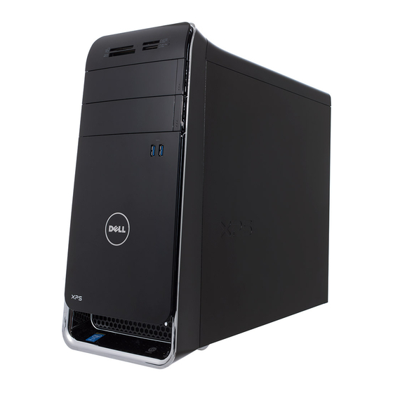
- Page 1 XPS 8700 Owner’s Manual Computer model: XPS 8700 Regulatory model: D14M Regulatory type: D14M001...
- Page 2 WARNING: A WARNING indicates a potential for property damage, personal injury, or death. ____________________ © 2013 Dell Inc. Trademarks used in this text: Dell™, the DELL logo, and XPS™ are trademarks of Dell Inc.; ® ® Microsoft and Windows are registered trademarks of Microsoft Corporation in the United ®...
-
Page 3: Table Of Contents
Contents Before You Begin ......Turn Off Your Computer and Connected Devices ..Safety Instructions . - Page 4 Removing the Graphics-Card Bracket (optional) ......Prerequisites ......Procedure .
- Page 5 Replacing the Primary Hard-Drive ... . Procedure ......Postrequisites .
- Page 6 Replacing the Top Cover ....Procedure ......Postrequisites .
- Page 7 Replacing the Chassis Fan ....Procedure ......Postrequisites .
- Page 8 Replacing the System Board ....Procedure ......Postrequisites .
-
Page 9: Before You Begin
Before You Begin Turn Off Your Computer and Connected Devices CAUTION: To avoid losing data, save and close all open files and exit all open programs before you turn off your computer. Save and close all open files and exit all open programs. Move your mouse pointer to the upper-right or lower-right corner of the screen to open the Charms sidebar, and then click Settings→... -
Page 10: Safety Instructions
For additional safety best practices information, see the Regulatory Compliance Homepage at dell.com/regulatory_compliance. WARNING: Disconnect all power sources before opening the computer cover or panels. After you finish working inside the computer, replace all covers, panels, and screws before connecting to the power source. -
Page 11: After Working Inside Your Computer
After Working Inside Your Computer After you complete the replacement procedures, ensure the following: • Replace all screws and ensure that no stray screws remain inside your computer. • Place the computer in an upright position. • Connect any external devices, cables, cards, and any other part(s) you removed before working on your computer. -
Page 12: Technical Overview
9. After working inside your computer, follow the instructions in "After Working Inside Your Computer" on page 11. For additional safety best practices information, see the Regulatory Compliance Homepage at dell.com/regulatory_compliance. Inside View of Your Computer front bezel primary hard-drive... -
Page 13: System-Board Components
System-Board Components 5 5 6 7 8 chassis fan connector power connector (PWRCONN1) (SYS_FAN 1) processor socket processor fan connector (CPU_FAN) memory module connector memory module connector (DIMM3) (DIMM1) memory module connector memory module connector (DIMM4) (DIMM2) main power connector CMOS reset jumper (RTCRST) (PWR1) Technical Overview... - Page 14 mSATA slot (MSATA1) SATA 3.0 (6 Gb/s) drive connector (SATA 2) SATA 3.0 (6 Gb/s) drive connector SATA 3.0 (6 Gb/s) drive connector (SATA 4) (SATA 3) front panel USB connector front panel USB connector (F_USB3) (F_USB2) SATA 3.0 (6 Gb/s) drive connector power button connector (SATA 1) (F_PANEL)
-
Page 15: Removing The Computer Cover
9. After working inside your computer, follow the instructions in "After Working Inside Your Computer" on page 11. For additional safety best practices information, see the Regulatory Compliance Homepage at dell.com/regulatory_compliance. Procedure Lay the computer on its side with the computer cover facing up. -
Page 16: Replacing The Computer Cover
9. After working inside your computer, follow the instructions in "After Working Inside Your Computer" on page 11. For additional safety best practices information, see the Regulatory Compliance Homepage at dell.com/regulatory_compliance. Procedure Connect all the cables and fold the cables out of the way. -
Page 17: Removing The Memory Module(S)
9. After working inside your computer, follow the instructions in "After Working Inside Your Computer" on page 11. For additional safety best practices information, see the Regulatory Compliance Homepage at dell.com/regulatory_compliance. Prerequisites Remove the computer cover. See "Removing the Computer Cover" on page 15. -
Page 18: Replacing The Memory Module(S)
Dell. If possible, do not pair an original memory module with a new memory module. Otherwise, your computer may not start properly. - Page 19 Press out the securing clip at each end of the memory-module connector. Align the notch on the bottom of the memory module with the tab on the memory-module connector. cutouts (2) memory-module connector notch memory module Replacing the Memory Module(s)
-
Page 20: Postrequisites
Insert the memory module into the memory-module connector until the memory module snaps into position. If you insert the memory module correctly, the securing clips snap into the cutouts at each end of the memory module. securing clip (snapped in position) memory-module connector memory module Postrequisites... -
Page 21: Removing The Front Bezel
9. After working inside your computer, follow the instructions in "After Working Inside Your Computer" on page 11. For additional safety best practices information, see the Regulatory Compliance Homepage at dell.com/regulatory_compliance. Prerequisites Remove the computer cover. See "Removing the Computer Cover" on page 15. -
Page 22: Procedure
Procedure Place the computer in an upright position. Grasp and release the front bezel tabs sequentially, one at a time by moving them outward from the front panel. Rotate and pull the front bezel away from the front of the computer to release the front bezel clamps from the front panel slots. -
Page 23: Replacing The Front Bezel
9. After working inside your computer, follow the instructions in "After Working Inside Your Computer" on page 11. For additional safety best practices information, see the Regulatory Compliance Homepage at dell.com/regulatory_compliance. Procedure Align and insert the front bezel clamps into the front panel slots. -
Page 24: Removing The Graphics-Card Bracket (Optional)
9. After working inside your computer, follow the instructions in "After Working Inside Your Computer" on page 11. For additional safety best practices information, see the Regulatory Compliance Homepage at dell.com/regulatory_compliance. Prerequisites Remove the computer cover. See "Removing the Computer Cover" on page 15. -
Page 25: Replacing The Graphics-Card Bracket (Optional)
9. After working inside your computer, follow the instructions in "After Working Inside Your Computer" on page 11. For additional safety best practices information, see the Regulatory Compliance Homepage at dell.com/regulatory_compliance. Procedure Align the screw holes on the graphics-card bracket with the screw holes on the chassis. -
Page 26: Removing The Graphics Card
Working Inside Your Computer" on page 11. For additional safety best practices information, see the Regulatory Compliance Homepage at dell.com/regulatory_compliance. The system board of your computer is equipped with one PCI-Express x16 connector to install graphics card. To locate the PCI-Express x16 connector on the system board, see "System-Board Components"... -
Page 27: Procedure
Procedure Remove the screw that secures the card-retention bracket to the chassis. Lift the card-retention bracket and set it aside in a secure location. NOTE: Your graphics card may have power-cable connectors. Press the releasing clips on the power-cable connectors and disconnect the power cable from the graphics card, if applicable. - Page 28 Press and hold the securing tab on the card connector, grasp the card by its top corners, and then ease the card out of the card connector. securing tab graphics card Removing the Graphics Card...
-
Page 29: Replacing The Graphics Card
9. After working inside your computer, follow the instructions in "After Working Inside Your Computer" on page 11. For additional safety best practices information, see the Regulatory Compliance Homepage at dell.com/regulatory_compliance. Procedure Align the graphics card with the PCI-Express x16 card connector on the system board. -
Page 30: Removing The Wireless Mini-Card
9. After working inside your computer, follow the instructions in "After Working Inside Your Computer" on page 11. For additional safety best practices information, see the Regulatory Compliance Homepage at dell.com/regulatory_compliance. Prerequisites Remove the computer cover. See "Removing the Computer Cover" on page 15. - Page 31 Slide and remove the wireless mini-card out of the wireless mini-card connector. wireless mini-card connector wireless mini-card Removing the Wireless Mini-Card...
-
Page 32: Replacing The Wireless Mini-Card
9. After working inside your computer, follow the instructions in "After Working Inside Your Computer" on page 11. For additional safety best practices information, see the Regulatory Compliance Homepage at dell.com/regulatory_compliance. Procedure CAUTION: To avoid damage to the wireless mini-card, ensure that no cables are placed under the wireless mini-card. -
Page 33: Removing The Msata Drive
9. After working inside your computer, follow the instructions in "After Working Inside Your Computer" on page 11. For additional safety best practices information, see the Regulatory Compliance Homepage at dell.com/regulatory_compliance. Prerequisites Remove the computer cover. See "Removing the Computer Cover" on page 15. -
Page 34: Replacing The Msata Drive
9. After working inside your computer, follow the instructions in "After Working Inside Your Computer" on page 11. For additional safety best practices information, see the Regulatory Compliance Homepage at dell.com/regulatory_compliance. Procedure Align the notch on the mSATA drive with the tab on the system-board connector. -
Page 35: Removing The Primary Hard-Drive
Working Inside Your Computer" on page 11. For additional safety best practices information, see the Regulatory Compliance Homepage at dell.com/regulatory_compliance. WARNING: If you remove the hard drive from the computer when the drive is hot, do not touch the metal housing of the hard drive. -
Page 36: Procedure
Procedure Disconnect the power and data cables from the primary hard-drive. Remove the screws that secure the hard drive to the chassis. Slide the hard drive out towards the back of the computer. power cable data cable primary hard-drive screws (4) Removing the Primary Hard-Drive... -
Page 37: Replacing The Primary Hard-Drive
9. After working inside your computer, follow the instructions in "After Working Inside Your Computer" on page 11. For additional safety best practices information, see the Regulatory Compliance Homepage at dell.com/regulatory_compliance. Procedure Slide the primary hard-drive into the hard-drive cage. -
Page 38: Removing The Hard-Drive Cage
9. After working inside your computer, follow the instructions in "After Working Inside Your Computer" on page 11. For additional safety best practices information, see the Regulatory Compliance Homepage at dell.com/regulatory_compliance. Prerequisites Remove the computer cover. See "Removing the Computer Cover" on page 15. -
Page 39: Replacing The Hard-Drive Cage
9. After working inside your computer, follow the instructions in "After Working Inside Your Computer" on page 11. For additional safety best practices information, see the Regulatory Compliance Homepage at dell.com/regulatory_compliance. Procedure Align the screw holes on the hard-drive cage with the screw holes on the chassis. -
Page 40: Removing The Secondary Hard-Drive (Optional)
Working Inside Your Computer" on page 11. For additional safety best practices information, see the Regulatory Compliance Homepage at dell.com/regulatory_compliance. WARNING: If you remove the hard drive from the computer when the drive is hot, do not touch the metal housing of the hard drive. -
Page 41: Replacing The Secondary Hard-Drive (Optional)
9. After working inside your computer, follow the instructions in "After Working Inside Your Computer" on page 11. For additional safety best practices information, see the Regulatory Compliance Homepage at dell.com/regulatory_compliance. Procedure Slide the secondary hard-drive into the hard-drive cage. -
Page 42: Installing A Third Hard-Drive (Optional)
9. After working inside your computer, follow the instructions in "After Working Inside Your Computer" on page 11. For additional safety best practices information, see the Regulatory Compliance Homepage at dell.com/regulatory_compliance. CAUTION: Hard drives are fragile. Exercise care when handling the hard drive. Prerequisites Remove the computer cover. - Page 43 Gently slide the third hard-drive into the hard-drive bay through the front of the computer. third hard-drive Installing a third Hard-Drive (optional)
-
Page 44: Postrequisites
Replace the screws that secure the third hard-drive to the chassis. Connect the power and data cables to the third hard-drive. power cable data cable screws (2) Postrequisites Replace the front bezel. See "Replacing the Front Bezel" on page 23. Replace the computer cover. -
Page 45: Removing The Optical Drive
9. After working inside your computer, follow the instructions in "After Working Inside Your Computer" on page 11. For additional safety best practices information, see the Regulatory Compliance Homepage at dell.com/regulatory_compliance. Prerequisites Remove the computer cover. See "Removing the Computer Cover" on page 15. -
Page 46: Replacing The Optical Drive
9. After working inside your computer, follow the instructions in "After Working Inside Your Computer" on page 11. For additional safety best practices information, see the Regulatory Compliance Homepage at dell.com/regulatory_compliance. Procedure Gently slide the optical drive into the optical-drive bay through the front of the computer. -
Page 47: Removing The Top Cover
9. After working inside your computer, follow the instructions in "After Working Inside Your Computer" on page 11. For additional safety best practices information, see the Regulatory Compliance Homepage at dell.com/regulatory_compliance. Prerequisites Remove the computer cover. See "Removing the Computer Cover" on page 15. -
Page 48: Replacing The Top Cover
9. After working inside your computer, follow the instructions in "After Working Inside Your Computer" on page 11. For additional safety best practices information, see the Regulatory Compliance Homepage at dell.com/regulatory_compliance. Procedure Align the tabs on the top cover with the slots on the top panel. -
Page 49: Removing The Media-Card Reader
9. After working inside your computer, follow the instructions in "After Working Inside Your Computer" on page 11. For additional safety best practices information, see the Regulatory Compliance Homepage at dell.com/regulatory_compliance. Prerequisites Remove the computer cover. See "Removing the Computer Cover" on page 15. -
Page 50: Replacing The Media-Card Reader
9. After working inside your computer, follow the instructions in "After Working Inside Your Computer" on page 11. For additional safety best practices information, see the Regulatory Compliance Homepage at dell.com/regulatory_compliance. Procedure Gently slide the media-card reader guides into the slots in the top panel Replace the screws that secure the media-card reader to the front panel Connect the media-card reader cable to the media-card reader. -
Page 51: Removing The Top I/O Panel
9. After working inside your computer, follow the instructions in "After Working Inside Your Computer" on page 11. For additional safety best practices information, see the Regulatory Compliance Homepage at dell.com/regulatory_compliance. Prerequisites Remove the computer cover. See "Removing the Computer Cover" on page 15. - Page 52 top I/O panel top panel screws (2) USB cable connector (F_USB3) Audio cable connector (F_AUDIO1) Removing the Top I/O Panel...
-
Page 53: Replacing The Top I/O Panel
9. After working inside your computer, follow the instructions in "After Working Inside Your Computer" on page 11. For additional safety best practices information, see the Regulatory Compliance Homepage at dell.com/regulatory_compliance. Procedure Align the screw holes on the top I/O panel with the screw holes on the top panel. -
Page 54: Removing The Front Usb Panel
9. After working inside your computer, follow the instructions in "After Working Inside Your Computer" on page 11. For additional safety best practices information, see the Regulatory Compliance Homepage at dell.com/regulatory_compliance. Prerequisites Remove the computer cover. See "Removing the Computer Cover" on page 15. - Page 55 front USB panel screw USB panel cables Removing the Front USB Panel...
-
Page 56: Replacing The Front Usb Panel
9. After working inside your computer, follow the instructions in "After Working Inside Your Computer" on page 11. For additional safety best practices information, see the Regulatory Compliance Homepage at dell.com/regulatory_compliance. Procedure Align and slide the front USB panel clamps into the front USB panel clamp slot. -
Page 57: Removing The Power Button Module
9. After working inside your computer, follow the instructions in "After Working Inside Your Computer" on page 11. For additional safety best practices information, see the Regulatory Compliance Homepage at dell.com/regulatory_compliance. Prerequisites Remove the computer cover. See "Removing the Computer Cover" on page 15. - Page 58 power button module cable power button module tabs (4) power button module Removing the Power Button Module...
-
Page 59: Replacing The Power Button Module
9. After working inside your computer, follow the instructions in "After Working Inside Your Computer" on page 11. For additional safety best practices information, see the Regulatory Compliance Homepage at dell.com/regulatory_compliance. Procedure Align and push the power button module tabs into the slots on the top panel. -
Page 60: Removing The Chassis Fan
9. After working inside your computer, follow the instructions in "After Working Inside Your Computer" on page 11. For additional safety best practices information, see the Regulatory Compliance Homepage at dell.com/regulatory_compliance. Prerequisites Remove the computer cover. See "Removing the Computer Cover" on page 15. -
Page 61: Replacing The Chassis Fan
9. After working inside your computer, follow the instructions in "After Working Inside Your Computer" on page 11. For additional safety best practices information, see the Regulatory Compliance Homepage at dell.com/regulatory_compliance. Procedure Align the screw holes on the chassis fan with the screw holes on the chassis. -
Page 62: Removing The Processor Fan And Heat-Sink
Working Inside Your Computer" on page 11. For additional safety best practices information, see the Regulatory Compliance Homepage at dell.com/regulatory_compliance. WARNING: The heat sink may be hot during normal operation. Provide sufficient time for the heat-sink to cool before you touch it. - Page 63 processor fan cable processor fan and heat-sink assembly captive screws (4) Removing the Processor Fan and Heat-Sink...
-
Page 64: Replacing The Processor Fan And Heat-Sink
9. After working inside your computer, follow the instructions in "After Working Inside Your Computer" on page 11. For additional safety best practices information, see the Regulatory Compliance Homepage at dell.com/regulatory_compliance. Procedure Clean the thermal grease from the bottom of the heat-sink. -
Page 65: Removing The Processor
9. After working inside your computer, follow the instructions in "After Working Inside Your Computer" on page 11. For additional safety best practices information, see the Regulatory Compliance Homepage at dell.com/regulatory_compliance. CAUTION: Processors are fragile. Handle the processor only by the edges and do not touch the metal pins. - Page 66 Gently lift the processor and remove it from the processor socket. release lever securing tab processor cover socket processor Removing the Processor...
-
Page 67: Replacing The Processor
Working Inside Your Computer" on page 11. For additional safety best practices information, see the Regulatory Compliance Homepage at dell.com/regulatory_compliance. NOTE: The original thermal grease can be reused if the original processor and processor heat-sink are reinstalled together. If either the processor or the processor heat-sink is replaced, use the thermal grease provided in the kit to ensure that thermal conductivity is achieved. -
Page 68: Procedure
Procedure Ensure that the release lever on the processor socket is fully extended in the open position. CAUTION: You must position the processor correctly in the processor socket to avoid permanent damage to the processor. Align the notches on the processor with the tabs on the processor socket. Align the pin-1 corner on the processor with the pin-1 corner on the processor socket, and then place the processor in the processor socket. -
Page 69: Removing The Coin-Cell Battery
Working Inside Your Computer" on page 11. For additional safety best practices information, see the Regulatory Compliance Homepage at dell.com/regulatory_compliance. CAUTION: Removing the coin-cell battery resets the BIOS settings to default. It is recommended that you note the BIOS settings before removing the coin-cell battery. -
Page 70: Replacing The Coin-Cell Battery
Working Inside Your Computer" on page 11. For additional safety best practices information, see the Regulatory Compliance Homepage at dell.com/regulatory_compliance. WARNING: The battery may explode if installed incorrectly. Replace the battery only with the same or equivalent type. Discard used batteries according to the manufacturer’s instructions. -
Page 71: Removing The Power-Supply Unit
9. After working inside your computer, follow the instructions in "After Working Inside Your Computer" on page 11. For additional safety best practices information, see the Regulatory Compliance Homepage at dell.com/regulatory_compliance. Prerequisites Remove the computer cover. See "Removing the Computer Cover" on page 15. -
Page 72: Replacing The Power-Supply Unit
9. After working inside your computer, follow the instructions in "After Working Inside Your Computer" on page 11. For additional safety best practices information, see the Regulatory Compliance Homepage at dell.com/regulatory_compliance. Procedure Slide the power supply towards the back of the chassis. -
Page 73: Removing The System Board
9. After working inside your computer, follow the instructions in "After Working Inside Your Computer" on page 11. For additional safety best practices information, see the Regulatory Compliance Homepage at dell.com/regulatory_compliance. Prerequisites Remove the computer cover. See "Removing the Computer Cover" on page 15. -
Page 74: Procedure
Procedure NOTE: Your computer’s service tag is stored in the system board. You must enter the service tag in the BIOS after you replace the system board. NOTE: Before disconnecting the cables from the system board, note the location of the connectors, so that you can reconnect them correctly after you replace the system board. -
Page 75: Replacing The System Board
9. After working inside your computer, follow the instructions in "After Working Inside Your Computer" on page 11. For additional safety best practices information, see the Regulatory Compliance Homepage at dell.com/regulatory_compliance. Procedure Gently place the system board into the chassis and slide it towards the back of the computer. -
Page 76: System Setup
Entering System Setup Turn on (or restart) your computer. During POST, when the DELL logo is displayed, watch for the F2 prompt to appear and then press <F2> immediately. NOTE: The F2 prompt indicates that the keyboard has initialized. This prompt can appear very quickly, so you must watch for it, and then press <F2>. -
Page 77: System Setup Options
System Setup Screens The system setup screen displays current or changeable configuration information for your computer. Information on the screen is divided into three areas: the setup item, active help screen, and key functions. Setup Item — This field appears on the left Help Screen —... - Page 78 Main→ Processor Information Displays the processor type. Processor Type Displays the processor identification code. Processor ID Displays the number of processor cores in your Processor Core Count computer. Displays the processor’s total L1 cache size. Processor L1 Cache Displays the processor’s total L2 cache size. Processor L2 Cache Displays the processor’s total L3 cache size.
- Page 79 SATA 3 Displays the type of device connected. Device Type Displays the device identification code. Device ID Displays the size of the SATA device present in Device Size your computer. mSATA Device Displays the type of device connected. Device Type Displays the device identification code.
- Page 80 Advanced→ Onboard Device Configuration Allows you to enable or disable the onboard Onboard Audio Controller audio controller. Allows you to configure the integrated hard drive SATA Mode controller to ATA or AHCI. Allows you to enable or disable the onboard Onboard LAN Controller LAN controller.
-
Page 81: Tpm Security
Power If enabled, will wake the system using a Wake Up by Integrated network message. LAN/WLAN Allows you to select the action the computer takes AC Recovery when power is restored. Allows you to configure the DeepSx mode. DeepSx Power Policies Allows the computer to start up automatically at a Auto Power On pre-configured time. -
Page 82: Changing Boot Sequence
Changing Boot Sequence for the Current Boot You can use this feature to change the current boot sequence, for example, to boot from the optical drive to run Dell Diagnostics from the Drivers and Utilities disc. The previous boot sequence is restored at the next boot. -
Page 83: Clearing Forgotten Passwords
9. After working inside your computer, follow the instructions in "After Working Inside Your Computer" on page 11. For additional safety best practices information, see the Regulatory Compliance Homepage at dell.com/regulatory_compliance. Remove the computer cover. See "Removing the Computer Cover" on page 15. Locate the password jumper on the system board. -
Page 84: Clearing Cmos Settings
9. After working inside your computer, follow the instructions in "After Working Inside Your Computer" on page 11. For additional safety best practices information, see the Regulatory Compliance Homepage at dell.com/regulatory_compliance. Remove the computer cover. See "Removing the Computer Cover" on page 15. Locate the CMOS jumper on the system board. -
Page 85: Flashing The Bios
The BIOS may require flashing when an update is available or when replacing the system board. To flash the BIOS: Turn on the computer. Go to dell.com/support. If you have your computer's Service Tag, type your computer's Service Tag and click Submit. -
Page 86: More Information
View or Download the following documents to learn about your computer features: • Quick Start Guide: provides information about setting up your computer. • Specifications: provides information about your computer specifications. • Me and My Dell: provides information about your computer features. More Information...
Need help?
Do you have a question about the XPS 8700 and is the answer not in the manual?
Questions and answers