Table of Contents
Advertisement
Advertisement
Table of Contents

Related Manuals for Grizzly G1021


Summary of Contents for Grizzly G1021
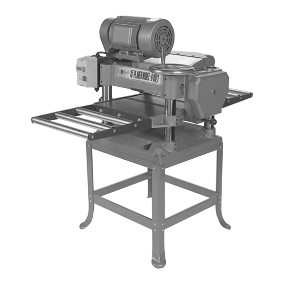
- Page 1 15" PLANER MODEL G1021 INSTRUCTION MANUAL COPYRIGHT © 1986 BY GRIZZLY INDUSTRIAL, INC. REG.# TX 3 170 572 WARNING: NO PORTION OF THIS MANUAL MAY BE REPRODUCED IN ANY SHAPE OR FORM WITHOUT THE WRITTEN APPROVAL OF GRIZZLY INDUSTRIAL, INC.
-
Page 3: Table Of Contents
TABLE ADJUSTMENT ...15-16 KNIFE INSPECTION ...16-17 KNIFE ADJUSTMENT ...17-18 CHIP BREAKER ...18-19 FEED ROLLER HEIGHT ...19-20 FEED ROLLER PRESSURE...20-21 BED ROLLERS ...21-22 CHIP DEFLECTOR ...22 ANTI-KICKBACK ...23 BELTS ...23-24 GEARBOX ...24-25 THICKNESS SCALE ...26 G1021 15" Planer Table Of Contents PAGE... - Page 4 TEST RUN ...29 WOOD SPECIES ...29 PLANING DIFFICULTIES ...30 MAINTENANCE ...31 GENERAL...31 TABLE...31 KNIVES...31 LUBRICATION...32-33 CLOSURE ...34 MACHINE DATA...35 TROUBLESHOOTING ...36 PARTS BREAKDOWN AND PARTS LISTS ...37-42 ADJUSTMENT BLOCK PATTERN...43 WARRANTY AND RETURNS ...44 Table Of Contents PAGE G1021 15" Planer...
-
Page 5: G1021 15" Planer
MENT. Don’t use power tools in damp or wet locations, or where any flammable or noxious fumes may exist. Keep work area well lighted. G1021 15" Planer WARNING Failure to obey a WARNING symbol and notation can result in serious injury to yourself and others. - Page 6 A guard or other part that is damaged should be properly repaired or replaced. blade or cutter against the direction of rota- tion of the blade or cutter only. TENDED. TURN POWER OFF. Don’t leave tool until it comes to a complete stop. G1021 15" Planer...
-
Page 7: Additional Safety Instructions For Planers
WARNING Like all power tools, there is danger asso- ciated with the Model G1021 15" Planer. Use the tool with respect and caution to lessen the possibility of mechanical dam- age or operator injury. If normal safety pre- cautions are overlooked or ignored. -
Page 8: Section 2: Circuit Requirements
SECTION 2: CIRCUIT REQUIREMENTS 220V Operation The G1021 Planer motor is wired to operate at 220V only. A cordset without a 220V plug is included with the Model G1021. Plugs and recep- tacles can be purchased at your local hardware store or home center. -
Page 9: Section 3: Introduction
SECTION 3: INTRODUCTION Commentary Grizzly Industrial, Inc. is proud to offer the Model G1021 15" Planer. The G1021 is part of Grizzly’s growing family of fine woodworking and metal- working machinery. When used according to the guidelines stated in this manual, you can expect years of trouble-free, enjoyable operation. -
Page 10: Unpacking
If you need advice regarding this situa- tion, please call us immediately. WARNING The G1021 is a heavy machine with a 475 lb. shipping weight. DO NOT over-exert your- self while unpacking or moving your machine – get assistance. In the event that... -
Page 11: Clean Up
Site Considerations FLOOR LOAD Your G1021 Planer represents a relatively large weight load in a small footprint. Most commercial floors are suitable for the Model G1021. Some residential floors may require additional support to accommodate both machine and operator. WORKING CLEARANCES... -
Page 12: Section 4: Assembly
SECTION 4: ASSEMBLY Overview Most of your G1021 Planer has been assembled at the factory, but some parts must be assembled or installed after delivery. We have organized the assembly process into steps. Please follow along in the order presented here. -
Page 13: Planer Unit
2. Secure the planer base to the stand with the four hex bolts, nuts, washer and fender wash- ers provided. -
Page 14: Handwheel
TO MOUNT THE HANDWHEEL: 1. Place the handwheel over the keyed shaft on the planer body. Make sure the key on the shaft and the keyway on the handwheel line up. The handwheel shaft is at the front right of the planer. -
Page 15: Extension Rollers
Figure 8. Extension roller attachment points. G1021 15" Planer Dust Port The G1021 Planer features a 4" dust port for use with a dust collection system. As with the extension rollers, you may find it more convenient to attach the dust port after making adjustments to the planer. -
Page 16: Section 5: Adjustments
SECTION 5: ADJUSTMENTS Overview Once assembly has been completed, your G1021 15" Planer requires just a few adjustments to ready it for use in your shop. Many adjustments have already been made at the factory, yet we recommend you familiarize yourself with all of the following procedures to gain a better understanding of the Planer’s con-... -
Page 17: Table Adjustment
Use the dial indicator whenever the instructions call for use of the gauge block and/or feeler gauge. Refer to the current Grizzly catalog for dial indicators. Figure 11. Guide block specifications. WARNING DO NOT make adjustments while the planer is running. -
Page 18: Knife Inspection
Figure 13 Cap screws for column adjustment. -18- Knife Inspection The Model G1021 Planer has a three-knife cut- terhead. The cutterhead is located in the head casting and rotates on two sealed bearings. No lubrication is needed for the life of the bearings. -
Page 19: Knife Setting
Improper knife height adjustment can result in damage to knives, poor planer per- formance and possible operator injury. G1021 15" Planer Knife Setting The process of setting the knives in the cutter- head will come into play whenever you sharpen or replace, or after determining that setting is necessary during the initial setup. -
Page 20: Chip Breaker
Figure 16. Tightening knives in cutterhead. Chip Breaker The chip breaker is located on the top side of the planer and extends down around the front of the cutterhead. Its function is to prevent tear-out or deep, unregulated gouging as the knives remove material. -
Page 21: Feed Roller Height
Re-tighten both locknuts Replace the exhaust hood. Figure 18. Chip breaker height adjustment. G1021 15" Planer Feed Roller Height The infeed and outfeed rollers propel the lumber through the planer. The rollers also press the lumber flat against the planer table. -
Page 22: Feed Roller Pressure
TO ADJUST ROLLER PRESSURE: Disconnect the machine from the power source. Ensure that knives and feed rollers are set correctly. Unscrew the four large pressure setscrews on top of the planer body. See Figure 21. Light Pressure Setscrew Regular Pressure Setscrews Figure 21. -
Page 23: Bed Rollers
Figure 22. Roller pressure assembly. Bed Rollers The bed rollers ease stock movement through the planer. The height of the bed rollers will vary depending on the types of wood you will be plan- ing. When planing rough stock, set the rollers slightly high to keep the lumber from dragging along the bed. -
Page 24: Chip Deflector
Re-tighten the chip deflector mounting bolts and re-mount the upper cover to the planer. Cutterhead Chipbreaker Figure 25. Chip deflector access. ⁄ " - ⁄ " from the tip of the cutting Mounting Bolts Chip Deflector G1021 15" Planer... -
Page 25: Anti-Kickback
Anti-Kickback The Model G1021 Planer provides an anti-kick- back safety feature. The anti-kickback fingers hang from a rod suspended across the front of the cutterhead casting. The anti-kickback fingers should be inspected regularly. Check the fingers to ensure that they swing freely and easily. See Figure 26. -
Page 26: Gearbox
-26- Gearbox The gearbox is located just behind the hand- wheel on the right side of the planer. The gearbox transfers power from the belt-driven cutterhead to the power feed rollers. The two-speed transmis- sion is controlled by a push/pull lever on the right side of the planer. - Page 27 Fill Plug Figure 30. Location of gearbox fill plug. Drain Plug Figure 31. Location of gearbox drain plug. G1021 15" Planer Extension Rollers N. EXTENSION ROLLERS If you elected to wait to install the extension rollers during the assembly process, install the extension rollers now.
-
Page 28: Thickness Scale
-28- Re-measure the board and compare your results with the scale. If there is a discrepan- cy, loosen the scale adjustment screw and correct the position. See Figure 33. Adjustment Screw NOTES Figure 33 G1021 15" Planer... -
Page 29: Table Locks
SECTION 6: Operations WARNING The Model G1021 15" Planer is a powerful woodworking machine, designed and con- structed for professional-quality applica- tions. Because of its powerful motor and razor-sharp knives, the Model G1021 is inherently dangerous and should be operat- ed with considerable caution and respect. -
Page 30: Power Feed
Take it slow and easy. The quality of your work will be better and your planer will last longer. Depth Limiter The Model G1021 is equipped with a depth lim- iter – located on the bottom of the cutterhead casting just under the nameplate. See Figure 36. -
Page 31: Test Run
Do not allow visitors into your workshop when testing or operating equip- ment. G1021 15" Planer Wood Species The species of wood, as well as its condition, have a dramatic effect on planing ability. The harder the wood (as illustrated by its shear strength), the more difficult it will be to plane. -
Page 32: Planing Difficulties
Using a dust collection system in combination with the planer can help reduce chip marks. Inspect the chip deflector and re-adjust as described earlier in the text. G1021 15" Planer... -
Page 33: Section 7: Maintenance
Table The table and other non-painted surfaces on the Model G1021 should be protected against rust and pitting. Wiping the table clean after every use ensures that moisture from wood dust isn’t allowed to trap moisture against bare metal sur- faces. -
Page 34: Lubrication
If the bad bearing is not replaced, it will eventually seize - possibly doing damage to other parts of the machine. Bearings are standard sizes and can be replaced through Grizzly. Proper lubrication of other components of the Model G1033 are essential for long life and trou- ble-free operation. - Page 35 See Figure 43. Lubrication ports on top of machine. Figures 43 and 44. Lead Screw Oil Can, 1-2 drops Column Figure 42. Lead Screw inside of column. Figure 44. Oiling lubrication ports. G1021 15" Planer -35-...
-
Page 36: Section 8: Closure
Washington location using the address in the Introduction. The specifications, drawings, and photographs illustrated in this manual represent the Model G1021 as supplied when the manual was prepared. However, due to Grizzly’s policy of continuous improvement, changes may be made at any time with no obligation on the part of Grizzly. -
Page 37: Machine Data
TROUBLESHOOTING This section covers the most common processing problems encountered in planing and what to do about them. Do not make any adjustments until planer is unplugged and moving parts have come to a complete stop. SYMPTOM POSSIBLE CAUSE Motor will not start. - Page 38 SEE PAGE 42-43 FOR REFERENCE NUMBER LISTING -38- G1021 15" Planer...
-
Page 39: Parts View
G1021 15" Planer 68-1 68-2 -39-... - Page 40 SEE PAGE 41-42 FOR REFERENCE NUMBER LISTING -40- G1021 15" Planer...
- Page 41 SEE PAGE 41-42 FOR REFERENCE NUMBER LISTING G1021 15" Planer -41-...
- Page 42 KEY 8 x 8 x 40mm CUTTERHEAD SPRING GIB BOLT CHAIN TENSIONER OIL PLUG OIL SEAL 28 x 40 x 8mm GEAR BOX GASKET BEARING 6204 - 2RS GEAR CAP SCREW M6 - 1.0 x 20mm BEARING 6201 - 2RS GEAR G1021 15" Planer...
- Page 43 OUTFEED ROLLER P1021152 SPRING P1021153 BUSHING BLOCK P1021154 CHIPBREAKER PN01M HEX NUT M6 - 1.0 PSS11M SET SCREW M6 - 1.0 x 16mm G1021 15" Planer Ref# Part# Description P1021157 CHIPBREAKER ADJUST ROD PR05M E-CLIP 15mm P1021160 SPACER P1021161 ANTI-KICKBACK FINGER...
- Page 44 -44- G1021 15" Planer...
-
Page 45: Adjustment Block Pattern
WARRANTY AND RETURNS Grizzly Industrial, Inc. warrants every product it sells for a period of 1 year to the original purchaser from the date of purchase. This warranty does not apply to defects due directly or indirectly to misuse, abuse, negligence, accidents, repairs or alterations or lack of maintenance.
Need help?
Do you have a question about the G1021 and is the answer not in the manual?
Questions and answers