Table of Contents

Related Manuals for Grizzly G1021Z


Summary of Contents for Grizzly G1021Z
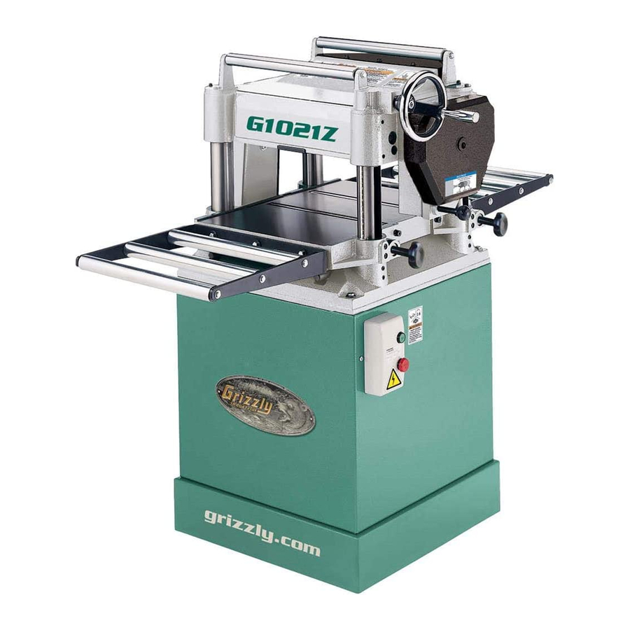
- Page 1 15" PLANER MODEL G1021Z INSTRUCTION MANUAL COPYRIGHT ©2000 BY GRIZZLY INDUSTRIAL, INC. WARNING: NO PORTION OF THIS MANUAL MAY BE REPRODUCED IN ANY SHAPE OR FORM WITHOUT THE WRITTEN APPROVAL OF GRIZZLY INDUSTRIAL, INC. JANUARY, 2000 PRINTED IN U.S.A.
-
Page 2: Table Of Contents
KNIFE INSPECTION ...17 KNIFE SHARPENING ...18 KNIFE SETTING ...19-20 CHIP BREAKER ...21 FEED ROLLER HEIGHT ...22 FEED ROLLER PRESSURE ...23 BED ROLLERS...24 CHIP DEFLECTOR...25 ANTI-KICKBACK ...26 BELTS ...26-27 GEARBOX ...27 THICKNESS SCALE ...28 Table Of Contents PAGE G1021Z 15" Planer... - Page 3 TABLE LOCKS ...29 POWER FEED ...30 HANDWHEEL ...30 DEPTH LIMITER ...30 TEST RUN ...31 WOOD SPECIES ...31 WOOD CHARACTERISTICS ...32 MAINTENANCE GENERAL...33 TABLE ...33 KNIVES...33 LUBRICATION ...34-35 CLOSURE ...36 TROUBLESHOOTING...37 ADJUSTMENT BLOCK PATTERN ...38 G1021Z 15" Planer Table Of Contents PAGE...
-
Page 4: Section 1: Safety
All children and visitors should be kept a safe distance from work area. padlocks, master switches, or by removing starter keys. better and safer at the rate for which it was designed. attachment to do a job for which it was not designed. G1021Z 15" Planer... - Page 5 12. SECURE WORK. Use clamps or a vise to hold work when practical. It’s safer than using your hand and frees both hands to operate tool. G1021Z 15" Planer 13. DON’T OVERREACH. Keep proper footing and balance at all times. 14. MAINTAIN TOOLS WITH CARE. Keep tools sharp and clean for best and safest performance.
-
Page 6: Additional Safety Instructions For Planers
Ensure that the planer is properly adjusted before using. Like all power tools, there is danger associ- ated with the Model G1021Z 15" Planer. Use the tool with respect and caution to lessen the possibility of mechanical damage or operator injury. If normal safety precau- tions are overlooked or ignored. -
Page 7: Section 2: Circuit Requirements
SECTION 2: CIRCUIT REQUIREMENTS 220V Operation The G1021Z Planer motor is wired to operate at 220V only. A cordset without a 220V plug is included with the Model G1021Z. Plugs and receptacles can be purchased at your local hard- ware store or home center. Contact your local electrical contractor if uncertain about connecting to a 220V circuit. -
Page 8: Section 3: General Information
SECTION 3: GENERAL INFORMATION Commentary We are proud to offer the Grizzly Model G1021Z 15" Planer. The Model G1021Z is part of a grow- ing Grizzly family of fine woodworking machinery. When used according to the guidelines set forth in this manual, you can expect years of trouble- free, enjoyable operation and proof of Grizzly’s... -
Page 9: Unpacking
If you need advice regarding this situation, please call us immediately. The G1021Z is a heavy machine with a 540 lb. shipping weight. DO NOT over-exert yourself while unpacking or moving your machine –... -
Page 10: Clean Up
Site Considerations FLOOR LOAD Your G1021Z Planer represents a large weight load in a small footprint. Most commercial floors are suitable for the Model G1021Z. Some resi- dential floors may require additional support to accommodate both machine and operator. WORKING CLEARANCES... -
Page 11: Assembly Overview
SECTION 4: ASSEMBLY Overview The G1021Z Planer requires very little assembly when you receive it. There a just a few easy assembly steps to get the machine ready for your shop. The machine should be properly adjusted from the factory, however should you desire to check the various settings, the following section will detail the proper adjustment procedures. -
Page 12: Speed Change Knob
5. Repeat steps 3-4 for the other extension roller assembly. Figure 6. Checking extension roller height. G1021Z 15" Planer Mounting Bolt... -
Page 13: Dust Port
Dust Port The G1021Z Planer features a 4" dust port for use with a dust collection system. If you will not be using a dust collection system with this plan- er, do not attach this dust port! TO ATTACH THE DUST PORT: 1. -
Page 14: Adjustments Overview
SECTION 5: ADJUSTMENTS Overview Once assembly has been completed, your G1021Z 15" Planer requires just a few adjust- ments to ready it for use in your shop. Many adjustments have already been made at the factory, yet we recommend you familiarize yourself with all of the following procedures to gain a better understanding of the Planer’s con-... -
Page 15: Table Adjustment
Use the dial indicator whenever the instructions call for use of the gauge block and/or feeler gauge. Refer to the current Grizzly catalog for dial indicators. Figure 10. Guide block specifications. DO NOT make adjustments while the planer is running. - Page 16 5. If the gap difference from one side to the other is greater than 0.016", the table raising chain under the planer base will need to be adjusted. Please call our Customer Service number for chain adjustment instructions. To adjust for gap differences of less than 0.016": 5.
-
Page 17: Knife Inspection
However it will not affect the adjustment if both the springs and jack screws are in place together. G1021Z 15" Planer Figure 14. Placing springs into knife slots. Jack Screw The knives of your planer must be periodically adjusted and will ultimately need to be removed for sharpening. -
Page 18: Knife Sharpening
For the best results it is best to have planer knives sharpened by a professional sharpening service which has the grinding and measurement equip- ment to assure that the knife cutting geometry is maintained at optimum levels. -
Page 19: Knife Setting
Make sure the gauge extension rod is parallel to the cutterhead to maintain accuracy. G1021Z 15" Planer Figure 18. Tightening knives in cutterhead. 5. Adjust the screws below each end of the knife until both feet of the gauge rest even-... - Page 20 Do not adjust one knife without adjusting the others as well. Improper knife height adjustment can result in damage to knives, poor planer per- formance and possible operator injury. Planer knives are dangerously sharp. Use...
-
Page 21: Chip Breaker
Chip Breaker The chip breaker is located on the top side of the planer and extends down around the front of the cutterhead. Its function is to prevent tear-out or deep, unregulated gouging as the knives remove material. The chip breaker works by breaking the woodchips as they are being cut by the cutter- head. -
Page 22: Feed Roller Height
Feed Roller Height The infeed and outfeed rollers propel the lumber through the planer. The rollers also press the lum- ber flat against the planer table. Set the infeed and outfeed rollers 0.040" below the knife edge at bottom dead center. -
Page 23: Feed Roller Pressure
1. Disconnect the machine from the power source. 2. Ensure that knives and feed rollers are set correctly. 3. Unscrew the four large pressure setscrews on top of the planer body. See Figure 25. Light Pressure Setscrew Regular Pressure Setscrews Figure 25. -
Page 24: Bed Rollers
Bed Rollers The bed rollers ease stock movement through the planer. The height of the bed rollers will vary depending on the types of wood you will be plan- ing. When planing rough stock, set the rollers slightly high to keep the lumber from dragging along the bed. -
Page 25: Chip Deflector
Cutterhead Chip Deflector Chipbreaker Figure 29. Chip deflector access. G1021Z 15" Planer 3. Move the deflector until its edge is approxi- 4. Re-tighten the chip deflector mounting bolts Planer knives are dangerously sharp. Use extreme caution when inspecting, remov- ing, sharpening, or replacing knives into the cutterhead. -
Page 26: Anti-Kickback
Anti-Kickback The Model G1021Z Planer provides an anti-kick- back safety feature. The anti-kickback fingers hang from a rod suspended across the front of the cutterhead casting. The anti-kickback fingers should be inspected regularly. Check the fingers to ensure that they swing freely and easily. See Figure 30. -
Page 27: Belts
G1021Z 15" Planer Gearbox The gearbox is located just behind the handwheel on the right side of the planer. The gearbox trans- fers power from the belt-driven cutterhead to the power feed rollers. The two-speed transmission is controlled by a push/pull lever on the right side of the planer. -
Page 28: Thickness Scale
-28- 4. Re-measure the board and compare your results with the scale. If there is a discrep- ancy, loosen the scale adjustment screw and correct the position. See Figure 34. Adjustment Screw Figure 34. Thickness scale. NOTES G1021Z 15" Planer... -
Page 29: Table Locks
SECTION 6: Operations The Model G1021Z 15" Planer is a powerful woodworking machine, designed and con- structed for professional-quality applica- tions. Because of its powerful motor and razor-sharp knives, the Model G1021Z is inherently dangerous and should be oper- ated with considerable caution and respect. -
Page 30: Power Feed
Make sure the height scale is properly adjusted. Depth Limiter The Model G1021Z is equipped with a depth lim- iter located on the bottom of the cutterhead cast- ing just under the nameplate. See Figure 37. The depth limiter controls maximum depth of cut to ". -
Page 31: Test Run
Be certain the safety glass- es you wear meet the appropriate stan- dards of the American National Standards Institute (ANSI). G1021Z 15" Planer Wood Species The species of wood, as well as its condition, have a dramatic effect on planing ability. The harder the wood (as illustrated by its shear strength), the more difficult it will be to plane. -
Page 32: Wood Characteristics
Using a dust collection system in combination with the planer can help reduce chip marks. Inspect the chip deflector and readjust (as described earlier in the text). G1021Z 15" Planer... -
Page 33: Section 7: Maintenance
Table The table and other non-painted surfaces on the Model G1021Z should be protected against rust and pitting. Wiping the table clean after every use ensures that moisture from wood dust isn’t allowed to trap moisture against bare metal sur- faces. -
Page 34: Lubrication
Bearings are standard sizes and can be replaced through Grizzly. Proper lubrication of other components of the Model G1021Z are essential for long life and trou- ble-free operation. Below is a list of components that require periodic lubrication. Schedules are based on daily use. - Page 35 The lead screws and columns should be wiped of any grease and dust build up once a week. They should be relubricated with light machine oil. See Figure 42. Lead Screw Column Figure 42. Lead Screw inside of column. G1021Z 15" Planer -35-...
-
Page 36: Section 8: Closure
Washington location using the address in the Introduction. The specifications, drawings, and photographs illustrated in this manual represent the Model G1021Z as supplied when the manual was prepared. However, due to Grizzly’s policy of continuous improvement, changes may be made at any time with no obligation on the part of Grizzly. -
Page 37: Troubleshooting
This section covers the most common processing problems encountered in planing and what to do about them. Do not make any adjustments until planer is unplugged and moving parts have come to a complete stop. See the section on Wood Characteristics for additional troubleshooting information. -
Page 38: Adjustment Block Pattern
-38- G1021Z 15" Planer... -
Page 39: Warranty And Returns
WARRANTY AND RETURNS Grizzly Industrial, Inc. warrants every product it sells for a period of 1 year to the original purchaser from the date of purchase. This warranty does not apply to defects due directly or indirectly to misuse, abuse, negligence, accidents, repairs or alterations or lack of maintenance.
Need help?
Do you have a question about the G1021Z and is the answer not in the manual?
Questions and answers