Table of Contents
Advertisement
Quick Links
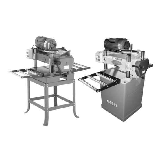
15" PLANER
MODEL G0550/G0551
INSTRUCTION MANUAL
COPYRIGHT © NOVEMBER 2003 BY GRIZZLY INDUSTRIAL, INC.
WARNING: NO PORTION OF THIS MANUAL MAY BE REPRODUCED IN ANY SHAPE
OR FORM WITHOUT THE WRITTEN APPROVAL OF GRIZZLY INDUSTRIAL, INC.
#5697 PRINTED IN CHINA
ONLINE MANUAL DISCLAIMER
THE INFORMATION IN THIS MANUAL REPRESENTS THE CONFIGURATION OF THE MACHINE AS IT IS CURRENTLY BEING SHIPPED. THE MACHINE
CONFIGURATION CAN CHANGE AS PRODUCT IMPROVEMENTS ARE INCORPORATED. IF YOU OWN AN EARLIER VERSION OF THE MACHINE, THIS
MANUAL MAY NOT EXACTLY DEPICT YOUR MACHINE . CONTACT CUSTOMER SERVICE IF YOU HAVE ANY QUESTIONS ABOUT DIFFERENCES. PRE-
VIOUS VERSIONS ARE NOT AVAILABLE ONLINE.
Advertisement
Table of Contents

Related Manuals for Grizzly G0550/G0551


Summary of Contents for Grizzly G0550/G0551
- Page 1 INSTRUCTION MANUAL COPYRIGHT © NOVEMBER 2003 BY GRIZZLY INDUSTRIAL, INC. WARNING: NO PORTION OF THIS MANUAL MAY BE REPRODUCED IN ANY SHAPE OR FORM WITHOUT THE WRITTEN APPROVAL OF GRIZZLY INDUSTRIAL, INC. #5697 PRINTED IN CHINA ONLINE MANUAL DISCLAIMER THE INFORMATION IN THIS MANUAL REPRESENTS THE CONFIGURATION OF THE MACHINE AS IT IS CURRENTLY BEING SHIPPED. THE MACHINE CONFIGURATION CAN CHANGE AS PRODUCT IMPROVEMENTS ARE INCORPORATED.
- Page 2 WARNING Some dust created by power sanding, sawing, grind- ing, drilling, and other construction activities contains chemicals known to the State of California to cause cancer, birth defects or other reproductive harm. Some examples of these chemicals are: • Lead from lead-based paints. •...
-
Page 3: Table Of Contents
Feed Roller Height ...34 Bed Rollers...35 Feed Roller Pressure ...36 Chip Deflector ...37 SECTION 9: REFERENCE INFO ...38 Aftermarket Accessories ...39 G0550/G0551 Parts Breakdown ...42 Troubleshooting Guide...47 G0550/G0551 Wiring Diagram...48 Gauge Block Measurements ...49 Warranty & Returns ...50 Table Of Contents... -
Page 4: Section 1: Safety
G0550/G0551 15" Planer VISITORS... - Page 5 14. MAINTAIN TOOLS WITH CARE. Keep tools sharp and clean for best and safest performance. Follow instructions for lubri- cating and changing accessories. G0550/G0551 15" Planer 15. USE RECOMMENDED ACCESSORIES. 16. REDUCE THE RISK OF UNINTENTION- 17. CHECK DAMAGED PARTS. Before fur-...
-
Page 6: Additional Safety Instructions For Planers
Like all machines there is danger associated with the Model G0550/G0551. Accidents are frequently caused by lack of familiarity or failure to pay attention. Use this machine with respect and caution to lessen the pos- sibility of operator injury. -
Page 7: Section 2: Introduction
We are proud to offer the Model G0550/G0551 15" Planer. This machine is part of a growing Grizzly family of fine woodworking machinery. When used according to the guidelines set forth in this manual, you can expect years of trouble- free, enjoyable operation and proof of Grizzly’s... -
Page 8: Section 3: Circuit Requirements
SECTION 3: CIRCUIT REQUIREMENTS Amperage Draw The Model G0550/G0551 motor is wired to oper- ate at 220V only. The planer motors draw the fol- lowing amperage: Amperage Draw G0550 2 HP...12 Amps G0551 3 HP...18 Amps Circuit Breaker Use the following guidelines when choosing a cir-... -
Page 9: Circuit Capacity
If you find it absolutely necessary to use an extension cord at 220V with your Grizzly Planer: • Make sure the cord is rated for Standard Service (grade S) or better. -
Page 10: Section 4: Machine Features
SECTION 4: MACHINE FEATURES Motor V-Belt Cover Height Handwheel Depth Limiter Height Lock Knob Thickness Scale Power Switch Feed Rate Knob Bed Rollers Extension Rollers Figure 2. Machine features. G0550/G0551 15" Planer... -
Page 11: Common Terms & Definitions
The chip breaker prevents excessive chipping caused by the knives. Snipe: A gouge at the end of the board. G0550/G0551 15" Planer Pressure Bar: Rides on the planed surface behind the cutterhead. Prevents vibration, chattering and snipe. -
Page 12: Section 5: Set Up
Wear safety glasses dur- ing the entire set up process! Unpacking The Model G0550/G0551 was carefully packed when it left our warehouse. If you discover the machine is damaged after you have signed for delivery, please immediately call Customer Service at (570) 546-9663 for advice. - Page 13 Dust Port Hardware Bag ...1 — Phillips Head Screw M6-1.0 x 12 ...6 F. Legs ...4 G. Lower Braces ...4 H. Predrilled Upper Braces ...4 G0550/G0551 15" Planer DESCRIPTION A. Dust Port ...1 B. Extension Roller Hardware Bag ...1 ⁄...
-
Page 14: Hardware Recognition Chart
40mm 45mm 50mm 55mm 60mm 65mm 70mm 75mm Wing Slotted Screw Button Flange Head Bolt Screw Phillips Phillips Head Head Sheet Metal Bolt Screw ⁄ ⁄ ⁄ ⁄ ⁄ ⁄ G0550/G0551 15" Planer ⁄ ⁄ ⁄ ⁄ ⁄ ⁄ ⁄... -
Page 15: Site Considerations
See Figure 6 for the overall dimen- sions of the Model G0550/G0551. 48" 28" Figure 6. Overall machine dimensions. -
Page 16: Beginning Assembly
"-18...32 ⁄ " ...32 Connect the lower and upper braces to the legs of the stand with the carriage bolts, hex nuts and flat washers. See Figure 7. Figure 7. Upper and lower braces connected to leg. G0550/G0551 15" Planer... -
Page 17: Mounting Planer (G0550)
Place two 2x4 boards under the cutterhead of the planer unit. Note—Make sure that the boards are long enough so that they protrude from the planer at least 16" on each side. G0550/G0551 15" Planer The planer unit represents a heavy load at 400 pounds. -
Page 18: Dust Port
Secure the handwheel with the hex nut and washer. Attach the handle to the outer edge of the handwheel. Install the High/Low label around the hex nut. Figure 10. Installing handwheel. G0550/G0551 15" Planer... -
Page 19: Extension Rollers
Remove the three hex bolts and washers from below the outfeed and infeed tables. Position the extension rollers over the holes. Finger-tighten the hardware removed in step 2 to secure the extension rails to the planer as shown in Figure 11. Hex Bolts Level Adjust Setscrews Figure 11. -
Page 20: Knife Setting Jig
Slide the cast aluminum knife setting jig feet onto the rod. Snap the other E-clip onto the notch at the other end of the knife setting jig shaft. -18- E-Clip Figure 14. Knife setting jig. Jig Shaft Jig Feet G0550/G0551 15" Planer... -
Page 21: Start Up
Press the START button to turn the machine ON. The machine should run smoothly with little or no vibration. G0550/G0551 15" Planer For your convenience, the adjustments listed below have been performed at the factory and no further setup is required to operate your machine. -
Page 22: Section 6: Operations
Once the height has been set, tighten the lock knobs. See Figure 15. loose clothing Lock down the cutterhead with the cutter- head lock knobs before planing or snipe will occur. Cutterhead Locks Figure 15. Cutterhead lock knob. NOTICE G0550/G0551 15" Planer... -
Page 23: Power Feed
Power Feed The power feed can be set for two feed rates—16 FPM and 20 FPM. While the planer is running the feed rate can be changed by pulling the feed con- trol knob (Figure 16). Press the knob in towards the machine for 20 FPM and pull the knob out for 16 FPM. -
Page 24: Anti-Kickback
Cottonwood Type Western Larch Tamarack Douglas Fir Alaska Cedar Sitka Spruce Sugar Pine Cypress Redwood (OG) Red Cedar White Pine Balsam Fir G0550/G0551 15" Planer Shear (PSI) 2,480 2,330 2,080 2,000 1,950 1,700 1,510 1,370 1,080 Shear (PSI) 1,410 1,280... -
Page 25: Section 7: Maintenance
G0550/G0551 15" Planer Regular periodic maintenance on the Model G0550/G0551 will ensure optimum performance. Make a habit of inspecting the machine each time you use it. Before each use, look for the following condi- disconnect... -
Page 26: V-Belts
To tension the V-Belt: Disconnect the machine from the power source! Insert a wooden lever between the motor mount and the top of the planer as shown in Figure 20. Loosen These Bolts Figure 20. Tensioning Belt. Loosen the two bolts that hold the motor pul- ley assembly to the planer (Figure 19). -
Page 27: Gearbox
Gearbox The gearbox is located just behind the handwheel on the right side of the planer. The gearbox trans- fers power from the belt-driven cutterhead to the power feed rollers. The two-speed transmission is controlled by a push/pull lever on the right side of the planer. - Page 28 Daily lubrication of the feed rollers is crucial to the oper- ation of your planer. Lubricate before start-up. Apply a light oil, making sure that the lubricant penetrates the bearing. Figure 25. Feed roller lubrication points. G0550/G0551 15" Planer...
-
Page 29: Planing Difficulties
However, small amount of snipe is inevitable. G0550/G0551 15" Planer Snipe can be minimized by proper adjustment of the planer components, but complete removal of snipe is extremely unlikely. More likely, you will be able to reduce it to a tolerance of .002". -
Page 30: Section 8: Service Adjustments
This section is provided for your convenience—it is not a substitute for the Grizzly Service Department. If any adjustments arise that are not described in this manual, then feel free to call the Grizzly Service Department at (570) 546-9663. -
Page 31: Table Adjustment
— If the gap difference from one side to the other is equal to or less than 0.004", no further adjustment is necessary. G0550/G0551 15" Planer — If the gap difference from one side to the other is greater than 0.004", but less than 0.016", go to step 5. -
Page 32: Thickness Scale
" under the thick- Measure the board again and compare your results with the scale. If there is a discrepan- cy, loosen the scale adjustment screw and correct the position. See Figure 30. Figure 30. Screw for column adjustment. G0550/G0551 15" Planer... -
Page 33: Knife Inspection
Knife Inspection The Model G0550/G0551 Planer has a three- knife cutterhead. The cutterhead is located in the head casting and rotates on two sealed bearings. No lubrication is needed for the life of the bear- ings. Because of normal use and wear, the knives must be periodically sharpened, replaced or adjusted. -
Page 34: Knife Sharpening
Knife Sharpening For the best results, it is best to have planer knives sharpened by a professional sharpening service which has the grinding and measurement equipment to assure that the knife cutting geom- etry is maintained at optimum levels. Knife sharp-... -
Page 35: Chip Breaker
Repeat these steps for the other two knives. Figure 34. Tightening gib bolts in cutterhead. G0550/G0551 15" Planer Chip Breaker The chip breaker is located on the top side of the planer and extends down around the front of the cutterhead. -
Page 36: Feed Roller Height
Measure the clearance between the top of the gauge block and the edge of the knife with a feeler gauge. Note the measurement indicated on the feeler gauge. Infeed Roller Chipbreaker Figure 37. Feed roller height inspection. G0550/G0551 15" Planer Anti-Kickback Fingers... -
Page 37: Bed Rollers
G0550/G0551 15" Planer Bed Rollers The bed rollers ease stock movement through the planer. The height of the bed rollers will vary depending on the types of wood you will be plan- ing. When planing rough stock, set the rollers slightly high to keep the lumber from dragging along the bed;... -
Page 38: Feed Roller Pressure
Disconnect the machine from the power source! Ensure that knives and feed rollers are set correctly. Unscrew setscrews on top of the planer body. See Figure 41. Figure 41. Roller pressure setscrews. three regular pressure Regular Pressure Setscrews Light Pressure Setscrew G0550/G0551 15" Planer... -
Page 39: Chip Deflector
Pressure Spring Roller Check Nut Figure 42. Roller pressure assembly. G0550/G0551 15" Planer The chip deflector keeps chips from falling onto the outfeed roller. It is the orange plastic plate located under the top cover. The beveled edge of the chip deflector should be properly adjusted according to your dust collec- tion setup. -
Page 40: Section 9: Reference Info
(570) 546-9663. Trained service technicians will be glad to help you. If you have any comments regarding this manual, please write to Grizzly at the address below: Grizzly Industrial, Inc. Technical Documentation P.O. Box 2069... -
Page 41: Aftermarket Accessories
SHOP FOX Mobile Base—Model G8683 Make your planer mobile with this popular patent- ed mobile base. Planer Pals—See The Current Grizzly Catalog For Model #s. These patented jigs are remarkably simple to use an hold knives securely in place while you tighten them in the cutterhead. -
Page 42: Machine Data Sheet
Customer Service #: (570) 546-9663 • To Order Call: (800) 523-4777 • Fax #: (800) 438-5901 GRIZZLY MODEL G0550 15" PLANER Design Type ...Bench Model Overall Dimensions: Table Size...14 Height w⁄ Stand ...53'' Overall Length ...48'' Overall Width ...28'' Shipping Weight ...460 lbs. - Page 43 Customer Service #: (570) 546-9663 • To Order Call: (800) 523-4777 • Fax #: (800) 438-5901 GRIZZLY MODEL G0551 15" PLANER Design Type ...Bench Model Overall Dimensions: Table Size...14 Height w⁄ Stand ...53'' Overall Length ...48'' Overall Width ...28'' Shipping Weight ...560 lbs.
-
Page 44: G0550/G0551 Parts Breakdown
-42- G0550/G0551 15" Planer... - Page 45 G0550/G0551 15" Planer -43-...
- Page 46 -44- G0551 Stand G0550 Stand G0550/G0551 15" Planer...
- Page 47 CHIP DEFLECTOR P0550037 COLUMN CAP PSB05M CAP SCREW M8-1.25 X 50 P0550039 LOCKING KNOB P0550040 PB02M HEX BOLT M6-1 X 12 G0550/G0551 15" Planer PART # DESCRIPTION P0550042 HEAD CASTING P0550043 CHIP BREAKER SPRING P0550044 TENSIONING SETSCREW PSS11M SET SCREW M6-1 X 16...
- Page 48 SHORT TOP BRACE PB03 HEX BOLT 5/16-18 X 1 PCB02 CARRIAGE BOLT 5/16-18 X 1/2 PN02 HEX NUT 5/16-18 PLW04M LOCK WASHER 8MM PW01M FLAT WASHER 8MM P0550191 STAND TOP PW01M FLAT WASHER 8MM PN03M HEX NUT M8-1.25 G0550/G0551 15" Planer...
-
Page 49: Troubleshooting Guide
Table moves down while 1. Knives dull. cutting. 2. Cutterhead is not locked. G0550/G0551 15" Planer CORRECTIVE ACTION 1. Check power line for proper voltage. 2. Inspect all lead connections on motor for loose or open connections. 1. Inspect cord or plug for damaged insulation and shorted wires. -
Page 50: G0550/G0551 Wiring Diagram
G0550/G0551 Wiring Diagram Single Phase Power Source Black Black Green -48- White NO 13 Magnetic Switch NC 15 16 NC 14 NO Thermal Protection Circuit Breaker Reset MOTOR Black White Green Ground G0550 G0551 Black Disconnect power from machine before performing any electrical service. -
Page 51: Gauge Block Measurements
G0550/G0551 15" Planer -49-... -
Page 52: Warranty & Returns
Warranty & Returns Grizzly Industrial, Inc. warrants every product it sells for a period of 1 year to the original purchaser from the date of purchase. This warranty does not apply to defects due directly or indirectly to misuse, abuse, negligence, accidents, repairs or alterations or lack of maintenance. -
Page 53: Warranty Card
Do you think your purchase represents good value? ___Yes Would you recommend Grizzly Industrial to a friend? ___Yes Would you allow us to use your name as a reference for Grizzly customers in your area? Note: We never use names more than three times. ___Yes Comments:_________________________________________________... - Page 54 FOLD ALONG DOTTED LINE FOLD ALONG DOTTED LINE Send a Grizzly Catalog to a friend: Name_______________________________ Street_______________________________ City______________State______Zip______ GRIZZLY INDUSTRIAL, INC. P.O. BOX 2069 BELLINGHAM, WA 98227-2069 TAPE ALONG EDGES--PLEASE DO NOT STAPLE Place Stamp Here...
- Page 56 Buy Direct and Save with Grizzly Visit Our Website Today And Discover Why • • • ® – Trusted, Proven and a Great Value! Grizzly ® Is The Industry Leader! SECURE ORDERING ORDERS SHIPPED WITHIN 24 HOURS E-MAIL RESPONSE WITHIN ONE HOUR...
Need help?
Do you have a question about the G0550/G0551 and is the answer not in the manual?
Questions and answers