Nortec NH Series Installation And Operation Manual
Resistive element steam humidifier
Hide thumbs
Also See for NH Series:
- Installation manual (92 pages) ,
- Installation manual (42 pages) ,
- Installation manual (110 pages)
Table of Contents
Advertisement
Quick Links
Advertisement
Table of Contents

Related Manuals for Nortec NH Series


Summary of Contents for Nortec NH Series
- Page 1 Important: Read and save these instructions. This guide to be left with equipment. Series Installation and Operation Manual Includes installation, operation maintenance and troubleshooting information for your NHRS Resistive Element Steam Humidifier 2530618- | 08 SEP 2010...
- Page 2 WALTER MEIER LTD., except to the extent required for installation or maintenance of recipient’s equipment. All references to the NORTEC name should be taken as referring to WALTER MEIER LTD. Liability Notice NORTEC does not accept any liability for installations of humidity equipment installed by unqualified personnel or the use of parts/components/equipment that are not authorized or approved by NORTEC.
-
Page 3: Table Of Contents
TABLE OF CONTENTS 10-00 INTRODUCTION PRE-INSTALLATION ............3 PACKAGING . - Page 4 ...
- Page 5 Regardless of selecting On/Off or modulating control method, NORTEC humidifiers must have a closed circuit across its On/Off security loop control terminal to operate. NORTEC highly recommends the use of a high limit humidistat and an air proving switch in series for this function.
-
Page 6: Introduction
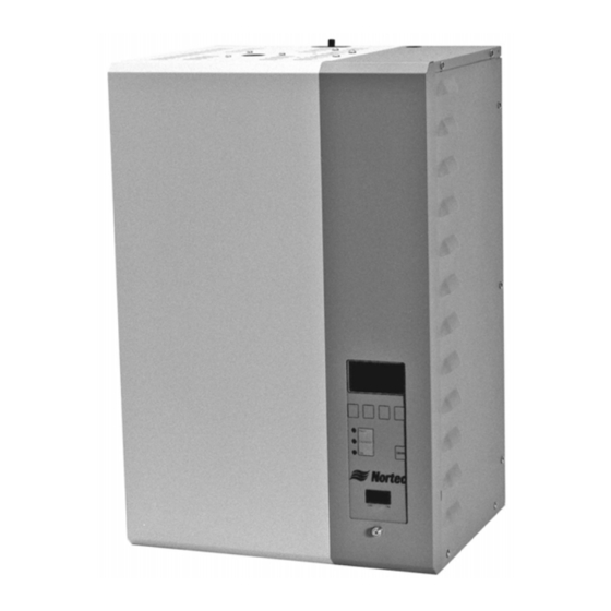
10-00 INTRODUCTION Page 1... - Page 7 Figure 1. NHRS Page 2...
-
Page 8: Pre-Installation
A. RECEIVING & UNPACKING EQUIPMENT (1) Check packing slip to ensure ALL material has been delivered. All material shortages are to be reported to NORTEC within 48 hours from the receipt of good. NORTEC assumes no responsibility for any material shortages beyond this period. - Page 9 HUMIDIFIER BAG WITH MANUAL, CLAMPS, STEAM HOSE HOSE SECTION SECTION (NOT SUPPLIED IF BUILT ON BLOWER PACK CONTROLS ORDERED) (IF ORDERED ONLY) BOX WITH ABBREVIATED INSTRUCTIONS AND BOX CONTENT STICKERS Figure 2. Humidifier Box Figure 3. Distributor Box Figure 4. SAM-e Distributor Box Figure 5.
-
Page 10: Pre-Installation Equipment Verification
3. PRE-INSTALLATION EQUIPMENT VERIFICATION A. GENERAL (1) Ensure the available voltage and phase correspond with humidifier voltage and phase as indicated on the humidifier’s specification label. (2) Ensure that the external fuse disconnect is sufficient size to handle the rated amperage as indicated on the humidifier’s specifications label. - Page 11 Figure 6. Typical NHRS Installation (Sheet 1 of 2) Page 6...
- Page 12 Figure 7. Typical NHRS Installation (Sheet 2 of 2) Page 7...
- Page 13 THIS PAGE INTENTIONALLY LEFT BLANK Page 8...
-
Page 14: Installation Procedures
10-10 INSTALLATION PROCEDURES Page 9... -
Page 15: Humidifier Installation
1. HUMIDIFIER INSTALLATION LOCATION The NORTEC NHRS series humidifier is designed to mount on a suitable wall or vertical surface. Do not sit the unit on the floor due to clearances required for plumbing and electrical connections. The clearance dimensions shown in this manual are for reference only and are the minimum required for maintenance on the humidifier. - Page 16 WATER SUPPLY LINE (Potable Water Supply) All water supply and drain line connections should be installed in accordance with local building codes. It is always recommended to install a manual shut off valve on the fill water supply line dedicated to the humidifier to facilitate servicing. Use 1/2 in. outside diameter copper piping to the humidifier.
- Page 17 Figure 1. Plumbing Connections Page 12...
- Page 18 WATER DRAIN LINE All water supply and drain line connections should be installed in accordance with local building codes. The NHRS comes equipped with a 1-1/2 in. drain outlet on the under side of the drain canal. Attach the factory supplied 1-1/2 in. hose to the drain outlet. A 1 in.
- Page 19 SCALE MANAGEMENT SYSTEM INSTALLATION Figure 2. Installation of the Scale Tank Bracket Line up holes in bracket with holes in drain pan. Fasten the bracket to the drain pan using the four #10-32 nylon lock nuts. Fasten the front of the bracket with the two #10-24 self tapping screws provided.
- Page 20 Figure 3. Installation of the Scale Tank Unlock support bracket by removing locking screws. Open both mechanisms by rotating counter clockwise until opening is visible. Place scale tank on support bracket. Rotate bracket to close mechanism and raise scale tank. Note ensure scale tank lines up with opening at the bottom of the drain pan when raising.
- Page 21 STEAM LINES AND CONDENSATE RETURNS Tables 1 through 5 indicate what material and recommended length to use when installing atmospheric steam lines. The lengths mentioned are equivalent feet and therefore the full length of steam line includes the addition of the equivalent length of all elbows and tees.
- Page 22 Notes: 1. This chart gives the maximum length of recommended steam line by unit size. 2. The use of steam line other then copper, stainless steel and Nortec steam hose will void the warranty and may cause adversely effect the operation of the humidifier 3.
- Page 23 Figure 4. Steam Run and Condensate Return Installation Guidelines (1 of 2) Page 18...
- Page 24 Figure 5. Steam Run and Condensate Return Installation Guidelines (2 of 2) Page 19...
- Page 25 Copper Tube (Potable) (RO or DI) 0.375 inch 0.250 inch. MED-L Tubing 1 x Steam Distributor 0.375 Tube 0.049 inch thick NORTEC 132-8840 (0.375 inch OD) 0.375 inch 0.500 inch. MED-L Tubing 3 x Steam Distributor 0.650 Tube 0.049 inch thick NORTEC 132-8840 (0.875 inch OD)
- Page 26 ELECTRICAL Local electrical codes should always be followed when installing a NORTEC Humidifier. Direct wiring to the high voltage terminal is shown in Figure 7. CONTROL WIRING Controls are available from NORTEC as accessories. If controls were not ordered with the humidifier they must be purchased or supplied by others. The following information is relevant to all controls, factory supplied or otherwise.
- Page 27 PRIMARY (LINE) VOLTAGE WIRING TO UNIT (BY OTHERS) WIRING TO BE PERFORMED BY A LICENSED ELECTRICIAN. GROUND WIRE GROUND GROUND DEDICATED 2 POLE CIRCUIT TERMINAL BREAKER OR FUSED BLOCK DISCONNECT - SINGLE PHASE UNIT. - SINGLE PHASE SUPPLY. - REQUIRED VOLTAGE BETWEEN L1 AND L2. - LOAD BALANCED.
- Page 28 254-8731 Figure 7. On/Off Guidelines and Low Voltage Terminal Strip Page 23...
- Page 29 Figure 8. NORTEC Control Guidelines and Wiring (Optional) Page 24...
- Page 30 When any key on the controller is pressed, the LCD screen will display the customer specified setpoint for a short duration. HUMIDITY TRANSDUCER SIGNAL INSTALLATION Figure 10 displays NORTEC optional humidity transducer installation. Figure 9. Setpoint vs. Outdoor Temperature Page 25...
- Page 31 Figure 10. NORTEC Humidity Transducer Guidelines and Wiring (Option) Page 26...
-
Page 32: Steam Distributor Installation For The Asd, Bsd, Csd
(c) CSD: 115 lbs/hour (45 kg/hour) C. DISTRIBUTOR LOCATIONS AND MOUNTING NORTEC distributors can be mounted in air handlers, supply air ducts or return air ducts. Return air ducts should only be considered if 100% of the return air enters the building again and is not exhausted by the air handling device. - Page 33 D. MULTIPLE DISTRIBUTOR APPLICATION The use of multiple steam distributors can reduce the absorption distance in most situations. (See Figure 13). CAUTION THESE INSTALLATION GUIDELINE APPLY FOR DUCT VELOCITIES UNDER 2000 FT/MIN (610M/MIN), PLEASE CONSULT FACTORY FOR HIGHER VELOCITY. CAUTION PLEASE MAKE SURE THAT NO OBSTACLES (ELBOW, FILTER, OR DIFFUSER) ARE LOCATED AFTER THE DISTRIBUTOR IN THE DIRECTION OF AIRFLOW CLOSER...
- Page 34 Figure 11. Leveling the Distributor Figure 12. Single Steam Distributor Figure 13. Multiple Steam Distributor Page 29...
- Page 35 Figure 14. Cutting Duct for Mounting Duct vertical clearance requirements for standard steam distributors are as follows. (a) ASD 8 in. vertical duct height for the 1 5 inches additional duct height for each additional ASD ROUNDDOWN („Duct height‟ – 8 inch / 5 inches) + 1) (b) BSD 10 in.
- Page 36 LOCATION OF STEAM DISTRIBUTORS WITHIN AN AIR HANDLER Humidify after the heating coil (H/C) so that absorption will occur before the cooling coil, any excess water will be drained away. There is little chance of condensation on the blower, blower motor, or fan isolation components, especially if you use a modulating high limit humidistat.
- Page 37 Figure 16. Roof Top Units 2-20 Tons – Figure 15. Best Location for Multiple Steam Distributors Typical Location Figure 17. Small Unit on Residential Furnace Page 32...
-
Page 38: Sam-E Short Absorption Manifold
SAM-e SHORT ABSORPTION MANIFOLD (1) Absorption distance is the minimum distance an obstruction can be placed downstream of the SAM-e to prevent condensing on the obstruction. (2) If any of the ducts of the AHU conditions are changed, the absorption distance may change due to a increase or decrease in the ducts temperature, amount of fresh air, various outside conditions, setpoint requirements, etc. - Page 39 (2) Installation with Adjustable Mounting Frame (Option, See Figure 21) (a) Insert the side panel into the base. (b) Fasten the pivoting head to the sliding panel with 0.375 in. UNC x 1 in. bolt, washer, and nut assembly (Factory Supplied). (c) Fasten side frame to the base of the manifold with 0.375 in.
- Page 40 Figure 18. SAM-e Tubes Figure 19. Steam Tube Offset Figure 20. Top Steam Tube Bracket Figure 21. Adjustable Mounting Frame Page 35...
- Page 41 Figure 22. Typical SAM-e Duct Installation Page 36...
- Page 42 B. OUTSIDE DUCT INSTALLATION (1) WITHOUT MOUNTING FRAME (a) Once you have selected the location of the manifold, cut out a 2 in. wide slot or a 2 in. diameter hole for each tube to be installed. (b) Insert all steam tubes into the main header, until flange is flush with the rubber gasket.
- Page 43 (f) Fasten the top of the steam tube bracket to secure all steam tubes using a bolt, washer, and nut assembly. (Factory Supplied). See Figure 20. (g) Fasten top steam tube bracket to side frame using bolt, washer, and nut assembly.
- Page 44 Figure 24. Vertical Duct Installation (8) Drill 8 x 0.500 in. (12.7mm) holes to match the mounting bracket‟s holes. (9) Fasten the manifold using a bolt, nut, and washer assembly. (Field Supplied). CAUTION DO NOT PULL OUT THE STEAM TUBES ONCE THEY HAVE BEEN INSTALLED, THIS COULD DAMAGE THE GASKET (10) Insert all steam tubes into the main header.
- Page 45 Figure 25. SAM-e Drain Water Cooling Page 40...
-
Page 46: Blower Packs
WARNING STEAM DISTRIBUTOR ON THE BUILT-ON AND REMOTE MOUNTED BLOWER PACKS HAVE A HOT SURFACE THAT COULD RESULT IN BURNS IF TOUCHED. NORTEC RECOMMENDS MOUNTING AT LEAST 8 FEET ABOVE THE FLOOR. A. BLOWER PACKS (1) Optional blower packs are used to distribute steam to localized areas such as computer rooms or in areas that do not have built-in air distribution systems. - Page 47 Figure 26. NHRS with remote Blower Pack Option Table 7. Ceiling and Frontal Clearances Minimum Number of Minimum Ceiling Minimum Frontal NHRS Series Model Blower Packs Clearance Clearance 18 (45) 30 (76) 18 (45) 30 (76) 18 (45) 36 (91) 18 (45) 72 (183) 36 (91)
- Page 48 (4) Field wiring of remote mounted blower pack must conform to national and local electrical codes. (5) For NH series use approved wire for power connections from 2 pole terminal block of the remote mounted blower pack to additional 2 pole terminal block inside the electrical section of the humidifier.
- Page 49 THIS PAGE INTENTIONALLY LEFT BLANK Page 44...
- Page 50 10-20 OPERATION Page 45...
-
Page 51: Operation
1. OPERATION INTRODUCTION The NORTEC NHRS Series humidifier is a completely new design based on up-to-date technology. The NHRS is designed to provide clean steam humidification at an economical price. The NHRS uses a microcomputer control system for greater flexibility. The NHRS has a liquid crystal display (LCD) to indicate system messages and display RH. -
Page 52: Nhrs Operation
STEAM GENERATION REGULATION The steam is produced in the steam tank by resistive heating element technology. Steam production is fully variable from 3 to 100%. FLUSHING - NHRS WITH SCALE MANAGEMENT (OPTIONAL) The evaporation process increases the concentration of minerals in the water of the steam cylinder. - Page 53 (b) Turn manual shut off valve to the flow through position providing water to the unit. (c) Switch on the external disconnect to provide voltage to the unit. NOTE If the Scale Management Option is used make sure the valve on the NHRS mineral tank is closed (d) Turn main power on via the rocker located on the keypad.
- Page 54 INITIAL START-UP PROCEEDURE The following procedure should be carried out only on the first occasion that the unit is operated: (a) Check the function of the steam humidifier 1. Switch on the humidification by raising the set humidity value on the humidity controller / humidistat / NHRS Display.
- Page 55 If the steam humidifier is equipped with the optional remote operating and fault indication (option ”RFS”), the operating status will be shown as follows: Table 2. Remote Fault Indication Steam (N/O) Normally open (N/O) Normally open Or (N/C) Normally Error closed (N/O) Normally open Or (N/C) Normally Service...
- Page 56 DISPLAY MENU NOTE The NHRS unit has a “display menu” from which various operating parameters can be viewed. It is not possible to change the values on the display level. Display level Operation (a) Call up the display level with <>or<>. (b) <>...
- Page 57 (b) Analog Input (humidity demand) 1. Current value of the signal applied to the analog input in [%] of its max. value. NOTE If the internal controller is active the displayed value corresponds to the current air humidity (%rh). (c) Internal Controller 1.
- Page 58 Value Setting Position Interval Minor Interval Major Maintenance Maintenance 200 hours 600 hours 300 hours 600 hours 300 hours 900 hours 450 hours 900 hours 400 hours 1200 hours 600 hours 1200 hours 500 hours 1500 hours 750 hours 1500 hours 3000 hours 3000 hours 6000 hours...
- Page 59 (f) Drain Cycle 1. The following indications are provided for the set-flushing interval Left: Switch setting on rotary switch “S1” (4 in example) Right: Set flushing interval (120 in example) NOTE The flushing interval is set on switch “S1” on the control board. Page 54...
- Page 60 Figure 2. Drain Interval Settings Page 55...
- Page 61 NOTE Should you have water conditions above the stated parameters consult the factory for a new blow-down setting to help improve your scale management. NORTEC recommends performing a semi-annual water analysis to ensure optimal performance. (f) Stand-by Heating 1. Stand-by heating activated (”on”) deactivated (”off”).
- Page 62 (g) Capacity Limitation 1. To change the Power Limit (Maximum Capacity) complete the following: Press both arrow key simultaneously Enter code “8808” Change to desired value Press both arrow keys simultaneously (h) Inlet Valve Correction 1. Set inlet valve correction (cycle ratio) in % of standard setting value to balance out water pressure variations.
- Page 63 Figure 3. Control Signal Setting Page 58...
- Page 64 (m) Flush Cycle 1. Flush Cycle activated (on), consult factory. Deactivated (off) factory set. (m) Control Signal 1. Range of the active analog signal in Volts or milliamps. NOTE The range of the analog signal may be adjusted using the rotary switch “S3” on the control board.
- Page 65 THIS PAGE INTENTIONALLY LEFT BLANK Page 60...
-
Page 66: Maintenance Procedures
10-30 MAINTENANCE PROCEDURES Page... -
Page 67: Nhrs Maintenance
ON THE HUMIDIFIER AND ANY OTHER EQUIPMENT PROVIDED BY NORTEC THAT REQUIRES MANTENANCE. NOTE Instruction and details concerning the maintenance of the NORTEC equipment must be observed and adhered to without fail. Only the maintenance documented in this manual must be carried out. - Page 68 (f) Confirm that the high voltage feed to the unit is off then remove the high voltage wires that connect to the top of the steam cylinder. NOTE The heating elements will not be affected if they are connected to different power lines when reinstalled.
- Page 69 Figure 1. Minor Maintenance with Scale Management Option Page 6...
- Page 70 MAJOR MAINTENANCE Manually drain the unit, then turn the unit main power switch to the off position. Switch the external electrical disconnect to the off position. WARNING THE NHRS HUMIDIFIER MAIN FUNCTION INVOLVES BRINGING WATER UP TO BOILING TEMERATURES. DO NOT LOSE SIGHT OF THE FACT THAT THE UNITS STEAM CYLINDER AND PLUMBING COMPONENTS MAY BE HOT!!!.
- Page 71 RESETTING MAINTENANCE INDICTION (1) Restore Primary voltage to the unit. (2) With the unit in the off position press and hold the drain activation switch. (3) Continue to hold the drain activation switch and turn the main power switch to the on position.
- Page 72 10-40 TROUBLESHOOTING Page 6...
-
Page 73: Troubleshooting
1. TROUBLESHOOTING NOTE Most operational malfunctions are not caused by faulty equipment but rather by improper installation or disregard for planning guidelines. Therefore, a complete fault diagnosis always involves a thorough examination of the entire system. Often, the steam hose connection has not been properly executed or the fault lies with the humidity control system. - Page 74 Max. Boil down rate too long Individual heating elements faulty. Replace faulty heating elements. Error code: 4A/4B Main voltage too low or failure of Replace fuses on power board. a phase (L1, L2 or L3). Steam Check main voltage and Error4B line too long or not insulated.
- Page 75 Figure 1. Wiring Diagram Page...
- Page 76 Figure 2. Wiring Diagram Page...
-
Page 77: Start-Up Check Lists
2. START-UP CHECK LISTS NHRS Electric Steam Humidifier Humidifier Mandatory Pre-Start-up Checklist (p.1 of 3) Unit Serial #: ____________ # of humidifiers: ____________ Tag:_____________ Unit type: NHRS Voltage: _____V/___ph Steam output: ____lbs./hr Customer/Job:_______________ Address: ____________________________________________________________________ Inspected by: ____________ Date of inspection: ___/___/___ WATER QUALITY: ... - Page 78 Humidifier Mandatory Pre-Start-up Checklist (p.2 of 3) DRAIN LINES: Air gap located within 3ft of the unit Slopped to drain Size:______________ WIRING: No loose wires around the unit or on the PC board? Yes CONTROLS: Location/Wiring/Setting Installed...
- Page 79 Humidifier Mandatory Start-up Checklist (p. 3 of 3) Unit Serial #: ____________ # of humidifiers: ____________ Tag:_____________ Unit type: NHRS Voltage: _____V/___ph Steam output: ____lbs./hr Customer/Job:___________ Address: ___________________________________________ Start-up by: _____________ Date of Start-up: ___/___/___ PRELIMINARY: Pre-start-up checklist completed? Yes If no, return to Pre-Start-up Checklist before going on with start-up procedure.
-
Page 80: Maintenance Check Lists
OPERATIONAL CHECK: 1. Switch on the humidification by raising the humidity set point on the humidistat/controller. 2. Switch off the humidification by lowering the humidity set point on the humidistat/controller. 3. Check for correct functioning of the external monitoring safeties such as air proving and high limit. 4. - Page 81 THIS PAGE INTENTIONALLY LEFT BLANK Page 7...
-
Page 82: Technical
10-50 TECHNICAL Page 7... -
Page 83: Exploded Views - Plumbing
Figure 1. Exploded View - Plumbing Page 7... - Page 84 Table 1. Exploded View - Plumbing Page 7...
-
Page 85: Exploded Views Electrical
Figure 2. Exploded View - Electrical Page... - Page 86 Table 2. Exploded View - Electrical Page...
-
Page 87: Warranty
Warranty Walter Meier Inc. and/or Walter Meier Ltd. (hereinafter collectively referred to as THE COMPANY), warrant for a period of two years after installation or 30 months from manufacturer’s ship date, whichever date is earlier, that THE COMPANY’s manufactured and assembled products, not otherwise expressly warranted (with the exception of the cylinder), are free from defects in material and workmanship. - Page 88 U.S.A. Walter Meier (Climate USA) Inc. 826 Proctor Avenue Ogdensburg, NY 13669 CANADA Walter Meier (Climate Canada) Ltd. 2740 Fenton Road Ottawa, Ontario K1T 3T7 TEL: 1.866.NORTEC1 FAX: 613.822.7964 EMAIL: northamerica.climate@waltermeier.com WEBSITE: www.humidity.com www.norteconline.com Certificate No. 002419...
Need help?
Do you have a question about the NH Series and is the answer not in the manual?
Questions and answers
What does code W11A mean?