Table of Contents
Advertisement
Quick Links
Advertisement
Table of Contents

Related Manuals for Nortec HP Series


Summary of Contents for Nortec HP Series
- Page 1 Important: Read and save these instructions. This guide to be left with equipment owner. HP Series Installation and Operation Manual Includes installation, operation maintenance and troubleshooting information for your HP Series humidifier 1507183-B| 25 OCT 2010...
- Page 2 WALTER MEIER LTD., except to the extent required for installation or maintenance of recipient’s equipment. All references to the Nortec name should be taken as referring to WALTER MEIER LTD. Liability Notice Nortec does not accept any liability for installations of humidity equipment installed by unqualified personnel or the use of parts/components/equipment that are not authorized or approved by Nortec.
-
Page 3: Table Of Contents
Contents To be updated upon 2 Introduction 37 HP HVAC Start-up Checklist About HP 38 Operation Receiving and Unpacking Equipment 39 Maintenance Absorption Distances 42 Danfoss Stainless Steel Axial Components To be updated upon comple Piston Pump Water Quality 42 Electrical Motor Service Multiple Zones 43 Inlet Water Filters 8 Installation... - Page 4 Regardless of selecting on/off or modulating control method, Nortec humidifiers must have a closed circuit across its on/off security loop control terminal to operate. Nortec highly recommends the use of a duct high limit humidistat. 1 | HP Series Installation Manual...
-
Page 5: Introduction
Receiving and Unpacking Equipment Check packing slip to ensure ALL material has been delivered. All material shortages are to be reported to Nortec within 48 hours from receipt of goods. Nortec assumes no responsibility for any material shortages beyond this period. -
Page 6: Absorption Distances
After unpacking, inspect equipment for damage and if damage is found, notify the shipper promptly. All Nortec products are shipped on an F.O.B. factory basis. Any and all damage, breakage or loss claims are to be made directly to the shipping company. - Page 7 Figure 1: Typical Installation with Medium Pump HP Series Installation Manual | 4...
- Page 8 Figure 2: Typical Installation with Large Pump 5 | HP Series Installation Manual...
-
Page 9: Water Quality
Care must be taken when laying out the piping between the pump and the valve blocks at each zone to prevent vibration transmission or water hammering effects. The piping should be securely supported using appropriate cushion clamps (by others) and long straight runs should be avoided. HP Series Installation Manual | 6... -
Page 10: Installation
Installation 7 | HP Series Installation Manual... -
Page 11: Pre-Installation
Follow manufacturers instructions when installing fittings. Recommended tube material: 304L stainless steel tube, ½” Outside Diameter, 0.049” Wall thickness Recommended fittings: 316 stainless steel, ½”, double ferrule compression connections. HP Series Installation Manual | 8... - Page 12 Vibration Isolation The pump skid will generate some degree of vibrations by its nature. It is recommended that the pump skid be installed on a vibration-damping mat or vibration isolators to reduce vibrations and noise. 9 | HP Series Installation Manual...
-
Page 13: Construction Of A Wet Duct Section
The section of ductwork that the HP HVAC manifolds are installed to be in needs to be capable of handling excess water that is not absorbed by the air. Nortec requires that a wet section be installed in the duct. The wet section should be as long as expected wetting distance. In most cases Nortec recommends the wet section extend 1.5 feet upstream and 6 feet downstream of... -
Page 14: Pump Module
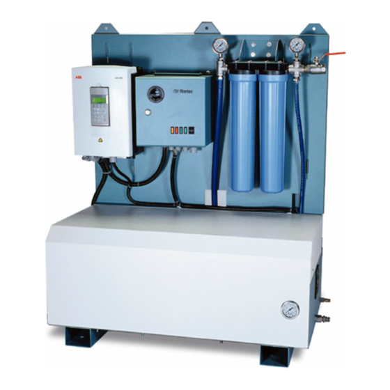
Brass Pumps). The water system capacity must be a minimum of 120% of the humidification system capacity. Running the pump on any voltage other than what is listed on the spec label can serious equipment damage and may ignite a fire. 11 | HP Series Installation Manual... - Page 15 Figure 3: Medium Pump Module Installation Drawing HP Series Installation Manual | 12...
- Page 16 Figure 4: Large Pump Module Installation Drawing 13 | HP Series Installation Manual...
-
Page 17: Installation Of The Hp Hvac Manifolds
HP manifolds. Figure 5: Vibration Clamps Securely fasten the gusset to vibration pad and duct walls with the supplied screws. (2 screws per gusset). Figure 6: Gusset HP Series Installation Manual | 14... - Page 18 The manifolds should be equally spaced in the duct. There should be at least 6” from the top of the duct to the mounting rails. Mounting rails should be installed on the upstream side of the manifolds. Figure 8: Rail and Clamp 15 | HP Series Installation Manual...
- Page 19 Install the air break end caps onto the one end of the HP manifolds. Figure 9: Endcap Install the manifold fittings to the bottom end of the HP manifolds. Figure 10: HP HVAC Manifold and Plumbing Installation HP Series Installation Manual | 16...
- Page 20 4” Min 4” Min 4” Min 4” Min 6” Min ZONE VAL VE ASS EMBLY 6” Min Figure 11: Manifold Minimum Spacing Figure 12: Nozzle Aiming 17 | HP Series Installation Manual...
-
Page 21: Installation Of The Piping Between Valve Block And Manifolds
Figure 13: Hydraulic Schematic for HP Systems It is strongly recommended to flush all lines with clean with clean water prior to installation. This prevents any accumulated dirt, loose flash, or metal fillings from degrading nozzle performance. HP Series Installation Manual | 18... -
Page 22: Check Valve
1.0 in. ( 24 mm ) Figure 14: P/N 2546701 – Check Valve Installation of the Needle Valve Connection Type - ½” compression fittings on the inlet and outlet. Install near inlet to valve block. 19 | HP Series Installation Manual... -
Page 23: Installation Of The Valve Block
RO system for processing. The drain line must flow to an open-air funnel. Solid connection to a drain can result in backflow, failure to drain, and dripping nozzles. HP Series Installation Manual | 20... - Page 24 Figure 15: Typical Valve Block Assembly 21 | HP Series Installation Manual...
-
Page 25: High Pressure Piping
In most cases this voltage will be 120VAC 60Hz single phase. At this voltage, the controller draws 2.7A (except high resolution systems). Install a dedicated disconnect on the electricity source to allow the controller to be isolated. HP Series Installation Manual | 22... -
Page 26: Wiring Of The System
The humidifier will only operate if there is continuity between terminals 1 and 2. If no on/off style safeties are to be used, install a jumper between terminals 1 and 2. 23 | HP Series Installation Manual... - Page 27 Time proportioning control: Connect a 0-10 humidistat to valve terminals 3 and 4. On/Off Control: Connect a humidistat between valve controller terminals 1 and 2. Also connect a jumper between terminals 1 and 3. HP Series Installation Manual | 24...
-
Page 28: Pump Controller Wiring Notes
Non-Nortec valve controllers can be used with the HP HVAC system. In these cases the valve controller is wired to the pump controller, as it would be with a Nortec valve controller. The valve controller need only close the loop, and does not need to provide a voltage or current. If the valve controller does provide a signal, it should be wired to a relay which will then close the pump controller loop. - Page 29 Figure 17: Valve Coils Figure 18: Valve Wiring HP Series Installation Manual | 26...
-
Page 30: Mist Eliminator Installation
Mist Eliminator Installation General The Nortec Mist Eliminator is a single bank water droplet removal system installed at a pre- defined distance from the water entry point. The highly humidified air is to come into contact with the Mist Eliminator and any un-absorbed droplets of water are removed from the air stream. - Page 31 Orient the mounting angle as shown in Detail A in Figure 21: Mounting Angles. Using field supplied self taping screws attach the mounting angle to the duct via the round mounting holes. A screw every 18 inches is recommended. Figure 20: Drainage and Drains Figure 21: Mounting Angles HP Series Installation Manual | 28...
- Page 32 If the duct height greater than 8 feet a channel extension is needed in order to link 2 mounting channels together. The extension slides inside the mounting channel. Use 4 ½ inch factory supplied screws for each mounting channel as shown in Figure 25: Mounting Channel Extension Kit. 29 | HP Series Installation Manual...
- Page 33 Figure 22: Mounting Channel Location Figure 23: Large Duct Mounting Channel Locations Figure 24: Mounting Channel Installation Figure 25: Mounting Channel Extension Kit HP Series Installation Manual | 30...
- Page 34 Be sure to install the wire mesh square when first fastened otherwise it will not align properly at the opposing end. Notch around screws previously installed for best results. Figure 27: Mesh Installation 31 | HP Series Installation Manual...
- Page 35 Place the strips so the 1 inch screw/studs pass through the slotted holes on the media clamping strip then fasten a factory supplied nut to hold the assembly in place. See Figure 29: Clamping Strip Installation. Figure 29: Clamping Strip Installation HP Series Installation Manual | 32...
- Page 36 33 | HP Series Installation Manual...
-
Page 37: Startup, Operation, And Maintenance
Startup, Operation, & Maintenance HP Series Installation Manual | 34... -
Page 38: Commissioning And Startup
(Terminal 3 is negative, terminal 4 is positive.) 10 Start the pump in manual mode and check for leaks in the system. The air handler should be operating during this step. 35 | HP Series Installation Manual... - Page 39 5 Ensure that the water hammer has decreased. Observe the nozzles to ensure that they are still spraying correctly. Note: After installing the needle valve, the manifolds may take a few seconds to charge and begin spraying. HP Series Installation Manual | 36...
- Page 40 Pump is installed and operating normally Manifolds and valves installed and operating normally Installed by: ___________________________________________________________________ (Company Name and Business Address) Inspected by: ___________________________________________________________________ (Company Name and Business Address) Signed: ____________________________ Date: _______________________ 37 | HP Series Installation Manual...
-
Page 41: Operation
8 Once every 24 hours, the valve controller will activate the system for 2 minutes to purge the lines of any standing water. This process occurs regardless of demand for humidity at that time. HP Series Installation Manual | 38... -
Page 42: Maintenance
100 hours before shutting down. The service and fault indicator lights will illuminate to indicate this condition. 3 Remember 500 hours is: Every 9 weeks if operated for 8 hours every day. Every 3 weeks if operated continuously for 24 hours per day. 39 | HP Series Installation Manual... - Page 43 - Synthetic 15w-50 grade oil can be used as an alternate grade. (Mobile1 or equivalent). Incorrect oil grades can cause pump damage. Damage resulting from incorrect oil grades is considered misuse and is not covered by warranty. HP Series Installation Manual | 40...
- Page 44 Figure 30: P200 Series Pumps Figure 31: P56W Pump Figure 32: P420A Pumps 41 | HP Series Installation Manual...
-
Page 45: Danfoss Stainless Steel Axial Piston Pump
2 The service indicator light will illuminate after 7900 hours of operation. The pump will continue to operate for another 100 hours after which time the service and fault indicators will illuminate and the pump will shut down. Nortec recommends replacing the pump at this time. Contact your local Nortec representative for further information. -
Page 46: Inlet Water Filters
Atomization Nozzles The Nortec HP HVAC system is designed to operate only on reverse osmosis or de-ionized water supplies. This allows for long trouble free operation of the nozzles. Occasionally because of either water quality or dirt, an atomization nozzle may become blocked. -
Page 47: Mist Eliminator Maintenance
Mist Eliminator Maintenance 1 The HP HVAC system should typically be installed downstream of air filters to minimize Mist Eliminator maintenance. In any case, Nortec recommends an annual inspection of mist eliminator media. 2 If the media is becoming contaminated with dust, it should be removed and cleaned with a vacuum or gentle water spray. -
Page 48: Decommissioning / Freeze Protecting
The inlet water pressure switch is hydraulically actuated, and completes a 24Vac control circuit. The switch is rated to 150 psi, and cut off sensitivity is adjustable between 12 and 100 psi. This switch is preset at 20 psi at the factory and does not require adjustment. 45 | HP Series Installation Manual... -
Page 49: Troubleshooting
Troubleshooting Troubleshooting | 46... - Page 50 Table 6: Troubleshooting Problem Cause / Solution Recommendations Pump module will not run. The power supply to pump is Turn the power supply on. off and needs to be turned on. Circuit breaker has interrupted Check that the power supply connection to the pumps power supply.
- Page 51 Transformer may be faulty. Check transformer line voltage and secondary voltage. Pump module has stopped Inlet water pressure has Check inlet water pressure for low conditions. running. dropped below 20 PSI. You may have to monitor gauge for water fluctuations.
- Page 52 49 | Troubleshooting...
-
Page 53: Spare Parts
Spare Parts Spare Parts | 50... - Page 54 Figure 35: Medium Pump Module Spare Parts 51 | Spare Parts...
- Page 55 Figure 36. Large Pump Module Spare Parts Spare Parts | 52...
- Page 56 Table 7: HP Spare Parts Nortec P/N Item Number Pump Model Giant 20” Filter 20” Filter 10” Filter Nortec Pumps, No Pump Motor LP Gauge HP Gauge Cartridge Cartridge Cartridge Part # 10 NOM 10 Abs 10 Abs G500 PM...
- Page 57 Nortec P/N Item Number Pump Model 20” Filter 20” Filter 10” Filter Giant Pump, Part # Cartridge Cartridge Cartridge Pump Motor With VFD Gauge Gauge 10 NOM 10 Abs 10 Abs GVFD950 PM 1506934 230V/3ph 1504259 1506495 1506492 1502839 1504307...
- Page 58 Nortec P/N Item Number Pump Model Danfoss 20” Filter 20” Filter 10” Filter Part # Pump, No Cartridge Cartridge Cartridge Pump Motor Gauge Gauge VFD Header 10 NOM 10 Abs 10 Abs D500 PM 1507182 120V/1ph 1506430 1504210 1503900 1506729...
- Page 59 Nortec P/N Item Number Pump Model 20” Filter 20” Filter 10” Filter Danfoss Cartridge Cartridge Cartridge Part # Pump, With 10 NOM 10 Abs 10 Abs Pump Motor Gauge Gauge DVFD500 PM 1506404 230V/3ph 1506430 1506495 1506492 1503900 1505279 1506377...
- Page 60 Table 8: Medium and Large Pump Module Spare Parts Number Description Part Number Switch N Series On Off Drain 1453001 Lamp Red 24VAC For NHC Panel 1493095 Lamp Green 24VAC For NCH/AF Panel 1493096 Lamp Amber 24VAC For AirFog 1603023 Pressure Switch 10 - 100 PSI 1504333 Fan Axial 118CFM 24 VDC...
- Page 61 Figure 37: 3 and 6 Stage Valve Assembly Spare Parts Spare Parts | 58...
- Page 62 59 | Spare Parts...
-
Page 63: Wiring & Installation Diagrams
Wiring & Installation Diagrams Wiring Diagrams | 60... - Page 64 Figure 38: Pump Control 61 | Wiring Diagrams...
- Page 65 Figure 39: Pump Controller with Danfoss VLT 2800 or VLT Aqua 800 Wiring Diagrams | 62...
- Page 66 Figure 40: Pump Controller with Danfoss Integrated VFD 63 | Wiring Diagrams...
- Page 67 Figure 41: 1 Stage Valve Controller Wiring Diagrams | 64...
- Page 68 Figure 42: 3 Stage Valve Controller 65 | Wiring Diagrams...
- Page 69 Figure 43: 6 Stage Valve Controller Wiring Diagrams | 66...
- Page 70 6.6 in. ( 168 mm ) 4.5 in. ( 114 mm ) 3.0 in. ( 75 mm ) 1.5 in. ( 39 mm ) 8.0 in. ( 203 mm ) 3.1 in. ( 80 mm ) 6.8 in. ( 171 mm) 3.6 in.
- Page 71 6.6 in. ( 168 mm ) 4.5 in. ( 114 mm ) 3.0 in. ( 75 mm ) 1.5 in. ( 39 mm ) 1/2" Compression O 0.4 in. ( 10 mm ) 4.1 in. ( 105 mm ) 6.8 in. ( 171 mm) 2.1 in.
- Page 72 6.6 in. ( 168 mm ) 4.5 in. ( 114 mm ) 3.0 in. ( 75 mm ) 1.5 in. ( 39 mm ) O 0.4 in. ( 10 mm ) 4.9 in. ( 123 mm ) 6.8 in. ( 171 mm) 2.9 in.
- Page 73 April 9, 2010 Figure 47: HP Valve Controller Wiring Diagrams | 70...
- Page 74 71 | Wiring Diagrams...
- Page 75 Warranty Walter Meier Inc. and/or Walter Meier Ltd. (hereinafter collectively referred to as THE COMPANY), warrant for a period of two years after installation or 30 months from manufacturer’s ship date, whichever date is earlier, that THE COMPANY’s manufactured and assembled products, not otherwise expressly warranted (with the exception of the cylinder), are free from defects in material and workmanship.
- Page 76 U.S.A. Walter Meier (Climate USA) Inc. 826 Proctor Avenue Ogdensburg, NY 13669 CANADA Walter Meier (Climate Canada) Ltd. 2740 Fenton Road Ottawa, Ontario K1T 3T7 TEL: 1.866.NORTEC1 FAX: 613.822.7964 EMAIL: nortec@waltermeier.com WEBSITE: www.humidity.com Certificate No. 002419...
Need help?
Do you have a question about the HP Series and is the answer not in the manual?
Questions and answers