Heatilator ADVT3428 Owner's Manual
Direct vent gas appliance heater
Hide thumbs
Also See for Heatilator ADVT3428:
- Specifications (4 pages) ,
- Owner's manual installation and operation (78 pages)
Table of Contents
Advertisement
Quick Links
Model(s):
ADVT3428, ADVR3428
ADVT3428I, ADVT3428IL
ADVR3428I, ADVR3428IL
• Important operating and
maintenance instructions
included.
WARNING
If the information in these instruc-
tions is not followed exactly, a
fi re may result causing property
damage, personal injury, or death.
• Do not store or use gasoline or other fl am-
mable vapors and liquids in the vicinity of
this or any other appliance.
• What to do if you smell gas:
- Do not try to light any appliance.
- Do not touch any electrical switch. Do not
use any phone in your building.
- Immediately call your gas supplier from
a neighbor's phone. Follow the gas
supplier's instructions.
- If you cannot reach your gas supplier, call
the fi re department.
• Installation and service must be performed
by a qualifi ed installer, service agency, or
the gas supplier.
This appliance may be installed as an OEM installation
in manufactured home (USA only) or mobile home and
must be installed in accordance with the manufacturer's
instructions and the manufactured home construction and
safety standard, Title 24 CFR, Part 3280 or Standard for
Installation in Mobile Homes, CAN/CSA Z240MH.
This appliance is only for use with the type(s) of gas
indicated on the rating plate.
CAUTION
DO NOT DISCARD THIS MANUAL
Read, understand and follow
•
these instructions for safe
installation and operation.
• CAREFULLY SUPERVISE children in same room as
• A l e r t c h i l d r e n a n d a d u l t s t o h a z a r d s o f h i g h
High temperatures may ignite clothing or other
fl ammable materials.
• Keep clothing, furniture, draperies and other combustibles
This appliance has been supplied with an integral
barrier to prevent direct contact with the fi xed glass
panel. Do NOT operate the appliance with the barrier
removed.
Contact your dealer or Hearth & Home Technologies if the
barrier is not present or help is needed to properly install one.
In the Commonwealth of Massachusetts installation must
be performed by a licensed plumber or gas fi tter;
See Table of Contents for location of additional
Commonwealth of Massachusetts requirements.
Heatilator • AVEO Series DV • 4058-210 Rev F • 10/08
Owner's Manual
Installation and Operation
Leave this manual with
•
party responsible for
use and operation.
WARNING
HOT SURFACES!
Glass and other surfaces are hot during
operation and cool down.
Hot glass will cause burns.
• Do not touch glass until it is cooled
• NEVER allow children to touch glass
• Keep children away
appliance.
temperatures.
away.
Installation and service of this appliance should be performed
by qualifi ed personnel. Hearth & Home Technologies suggests
NFI certifi ed or factory-trained professionals, or technicians
supervised by an NFI certifi ed professional.
1
Advertisement
Table of Contents

Related Manuals for Heatilator Heatilator ADVT3428


Summary of Contents for Heatilator Heatilator ADVT3428
- Page 1 Owner’s Manual Installation and Operation Model(s): ADVT3428, ADVR3428 ADVT3428I, ADVT3428IL ADVR3428I, ADVR3428IL CAUTION DO NOT DISCARD THIS MANUAL Read, understand and follow Leave this manual with • Important operating and • • these instructions for safe party responsible for maintenance instructions installation and operation.
-
Page 2: Congratulations
Read this manual before installing or operating this appliance. Please retain this owner’s manual for future reference. A. Congratulations This owner’s manual should be retained for future reference. We suggest that you keep it with your other important Congratulations on selecting a Heatilator gas fi replace, an documents and product manuals. -
Page 3: Table Of Contents
Safety Alert Key: • DANGER! Indicates a hazardous situation which, if not avoided will result in death or serious injury. • WARNING! Indicates a hazardous situation which, if not avoided could result in death or serious injury. • CAUTION! Indicates a hazardous situation which, if not avoided, could result in minor or moderate injury. •... - Page 4 14 Appliance Setup A. Remove the Packaging B. Open Front Screen Assembly C. Remove the Shipping Materials D. Remove Fixed Glass Assembly E. Clean the Appliance Accessories G. Place the Rockwool H. Place the Lava Rock Place the Vermiculite Remove Screen Protector K.
-
Page 5: Limited Lifetime Warranty
B. Limited Lifetime Warranty Hearth & Home Technologies LIMITED WARRANTY Hearth & Home Technologies (“HHT”) and its respective brands extends the following warranty for HHT gas, wood, pellet and electric appliances purchased from an authorized HHT dealer and installed in the United States of America or Canada. - Page 6 B. Limited Lifetime Warranty (continued) This limited warranty does not extend to or include surface fi nish on the appliance or terminations, door gasketing, glass gasketing, glass discoloration, fi rebrick, pellet logs, kaowool or other ceramic insulating materials. Rust and/or corrosion on any of the metal surfaces, cast iron components, baffl...
-
Page 7: Listing And Code Approvals
Listing and Code Approvals A. Appliance Certifi cation C. BTU Specifi cations Maximum Minimum Orifi ce MODELS: ADVT3428 Series, ADVR3428 Series Input Input Size Models BTU/h BTU/h (DMS) LABORATORY: Underwriters Laboratories, Inc. (UL) ADVR3428 TYPE: Direct Vent Gas Appliance Heater ADVT3428 18,000 12,750... -
Page 8: Requirements For The Commonwealth Of Massachusetts
Inspection Note: The following requirements reference various The state or local gas inspector of the side wall horizon- Massachusetts and national codes not contained in this tally vented gas fueled equipment shall not approve the document. installation unless, upon inspection, the inspector ob- serves carbon monoxide detectors and signage installed H. -
Page 9: User Guide
User Guide Operating Instructions A. Gas Fireplace Safety • Install a physical barrier such as: A decorative fi rescreen. WARNING Adjustable safety gate. • Install a switch lock or a wall/remote control with child HOT SURFACES! protection lockout feature. Glass and other surfaces are hot •... -
Page 10: Clear Space
E. Fixed Glass Assembly C. Clear Space See Section 14.N. WARNING! DO NOT place combustible objects in front of the fi replace or block louvers. High temperatures may start F. Remote Controls, Wall Controls and Wall a fi re. See Figure 2.2. Switches Avoid placing candles and other heat-sensitive objects on Follow the instructions supplied with the control installed... -
Page 11: Lighting Instructions (Ipi)
H. Lighting Instructions (IPI) • For normal use, activate/deactivate your fi replace with the wall switch or remote control. • The IPI system may be operated with two D-cell batteries. When using batteries, unplug the transformer. To prolong battery life, remove them when using the transformer. •... -
Page 12: Lighting Instructions (Standing Pilot)
I. Lighting Instructions (Standing Pilot) • For normal use, activate/deactivate your fi replace with the wall switch or remote control. • If your fi replace must be deactivated for service or an extended period of time, follow the instructions below. VENT Heatilator •... -
Page 13: After Fireplace Is Lit
J. After Fireplace is Lit Initial Break-in Procedure • The fireplace should be run three to four hours continuously on high. • Turn the fi replace off and allow it to completely cool. • Remove fi xed glass assembly. See Section 14.N. •... -
Page 14: Maintenance And Service
Maintenance and Service Doors, Surrounds, Fronts Any safety screen or guard removed for servicing must be Frequency: Annually replaced prior to operating the fi replace. By: Homeowner When properly maintained, your fi replace will give you Tools needed: Protective gloves, stable work surface many years of trouble-free service. -
Page 15: Maintenance Tasks-Qualifi Ed Service Technician
B. Maintenance Tasks-Qualifi ed Service Burner Ignition and Operation Technician Frequency: Annually The following tasks must be performed by a qualifi ed By: Qualifi ed Service Technician service technician. Tools needed: Protective gloves, vacuum cleaner, whisk Gasket Seal and Glass Assembly Inspection broom, fl... -
Page 16: Installer Guide
Installer Guide Getting Started A. Typical Appliance System NOTICE: Illustrations and photos refl ect typical installations and are for design purposes only. Illustrations/diagrams are not drawn to scale. Actual product may vary from pictures in manual Note: Dual venting confi gurations Horizontal ARE NOT allowed. -
Page 17: Design And Installation Considerations
B. Design and Installation Considerations D. Inspect Appliance and Components Heatilator direct vent gas appliances are designed to op- • Carefully remove the appliance and components from erate with all combustion air siphoned from outside of the the packaging. building and all exhaust gases expelled to the outside. No •... -
Page 18: Framing And Clearances
Framing and Clearances A. Select Appliance Location NOTICE: Illustrations refl ect typical installations and are FOR DESIGN PURPOSES ONLY. Illustrations/diagrams When selecting a location for the appliance it is important are not drawn to scale. Actual installation may vary due to to consider the required clearances to walls (see Fig- individual design preference. -
Page 19: Construct The Appliance Chase
B. Construct the Appliance Chase To further prevent drafts, the wall shield and ceiling fi re- stops should be caulked with high temperature caulk to A chase is a vertical box-like structure built to enclose the seal gaps. Gas line holes and other openings should be gas appliance and/or its vent system. -
Page 20: Mantel And Wall Projections
D. Mantel and Wall Projections WARNING! Risk of Fire! Comply with all minimum clear- ances to combustibles as specifi ed. Framing or fi nishing material closer than the minimums listed must be construct- ed entirely of noncombustible materials (i.e., steel studs, concrete board, etc). -
Page 21: Termination Locations
Termination Locations A. Vent Termination Minimum Clearances Direct Vent Gas, Wood or Fuel WARNING Oil Termination 20 in. Fire Risk. (508 mm) (minimum) to 18 in. Maintain vent clearance to combustibles as Perpendicular (457 mm) Wall specifi ed. (DV only) •... - Page 22 Fixed Openable Fixed Closed Closed GAS METER V TERMINATION CAP AIR SUPPLY INLET RESTRICTION ZONE (TERMINATION NOT ALLOWED) Measure vertical clearances from this surface Electrical Service Covered Alcove Measure horizontal clearances Clearances to Electrical Service Applications from this surface. Dimension Descriptions P 6”...
-
Page 23: Vent Information And Diagrams
Vent Information and Diagrams A. Approved Pipe This appliance is approved for use with Hearth & Home Technologies DVP (rear vent) or SLP (top vent) vent- ing systems. Refer to Section 16.B. for vent component information. Vertical DO NOT mix pipe, fi ttings or joining methods from differ- ent manufacturers. -
Page 24: Vent Diagrams
E. Vent Diagrams To replace the fi rst starter elbow with two 45° elbows, refer to Figure 7.4. All other 90° elbows can be replaced with two 45° elbows. General Rules: • SUBTRACT 3 ft. from the total H measurement for each 90°... - Page 25 1. Top Vent - Horizontal Termination - (continued) Two 45° Elbows replacing One 90° Elbow 4 ft min. (1.22 m) 25 ft max. (7.62 m) Figure 7.4 min. max. max. max. Two Elbows 6 in. 6 ft 152 mm 1.83 m 1 ft 11 ft 11 ft...
- Page 26 1. Top Vent - Horizontal Termination - (continued) min. max. max. Three Elbows 1 ft 24 ft 19 ft 305 mm 7.32 m 5.79 m Note: The fi rst elbow used in the system must be a starter elbow Figure 7.6 Heatilator •...
- Page 27 2. Top Vent - Vertical Termination No Elbow 12 ft (3.66 m) min. 60 ft (18.29 m) max. Figure 7.7 Figure 7.7b 12 ft to 30 ft Vertical Run Figure 7.7c 31 ft to 60 ft Vertical Run Install Baffl e •...
- Page 28 2. Top Vent - Vertical Termination - (continued) Two Elbows 12 ft (3.66 m) min. 60 ft (18.29 m) max. Maximum horizontal run is 100% of vertical, but cannot exceed 26 ft (7.92 m) Figure 7.8 Heatilator • AVEO Series DV • 4058-210 Rev F • 10/08...
- Page 29 2. Top Vent - Vertical Termination - (continued) Three Elbows Maximum horizontal run is 100% of vertical, but cannot exceed 26 ft (7.92 m) 12 ft (3.66 m) min. 60 ft (18.29 m) max. Figure 7.9 Heatilator • AVEO Series DV • 4058-210 Rev F • 10/08...
- Page 30 3. Rear Vent - Horizontal Termination No Elbow 18 in. (457 mm) max. Figure 7.10 One 45° Elbow 18 in. (457 mm) max. Figure 7.11 Heatilator • AVEO Series DV • 4058-210 Rev F • 10/08...
- Page 31 3. Rear Vent - Horizontal Termination - (continued) Total Vert Total Horiz Two Elbows Model V Min. ADVR 0-.61 0.31 0.91 1.22 0.61 1.83 1.83 0.91 2.74 2.44 1.22 3.66 2.44 1.52 4.57 2.44 1.83 5.49 Figure 7.12 Total Vert V Total Horiz H Three Elbows Model...
- Page 32 4. Rear Vent - Vertical Termination One Elbow 0 min. 6 ft (1.83 m) max. 12 ft (3.66 m) min. 60 ft (18.29 m) max. Figure 7.14 Two Elbows 0 min. 12 ft (3.66 m) min. 6 ft (1.83 m) max. 60 ft (18.29 m) max.
- Page 33 4. Rear Vent - Vertical Termination - (continued) Three Elbows 0 min. 6 ft (1.83 m) max. 12 ft (3.66 m) min. 60 ft (18.29 m) max. Maximum horizontal run is 100% of vertical, but can- not exceed 26 ft (7.92 m). Figure 7.16 Heatilator •...
-
Page 34: Vent Clearances And Framing
Vent Clearances and Framing A. Pipe Clearances to Combustibles B. Wall Penetration Framing WARNING! Risk of Fire! Maintain air space clearance to Combustible Wall Penetration vent. DO NOT pack insulation or other combustibles: Whenever a combustible wall is penetrated, you must frame a hole for the wall shield fi... -
Page 35: Install The Ceiling Firestop
C. Install the Ceiling Firestop A ceiling fi restop MUST be used between fl oors and attics. • DVP pipe only - Frame an opening 10 in. by 10 in. (254 mm by 254 mm) whenever the vent penetrates a ceiling/fl oor (see Figure ATTIC ABOVE 8.3). -
Page 36: Install Attic Insulation Shield
D. Install Attic Insulation Shield WARNING! Fire Risk. DO NOT allow loose materials or insulation to touch vent. Hearth & Home Technologies Inc. requires the use of an attic shield. The National Fuel Gas Code ANSI Z223.1 and NFPA 54 requires an attic shield constructed of 26 gauge minimum metal that extends at least 2 in. -
Page 37: Appliance Preparation
Appliance Preparation A. Secure and Level the Appliance WARNING! Risk of Fire! Prevent contact with: • Sagging or loose insulation • Insulation backing or plastic • Framing and other combustible materials Block openings into the chase to prevent entry of blown-in insulation. -
Page 38: Top Vent Only
B. Top Vent Only • Locate top heat sheld (Figure 9.2). • Remove back screws holding top heat shield (Figure 9.3). • Bend heat shield up. See Figure 9.4. • Install fi rst piece of vent pipe (Figure 9.5). Figure 9.4 Bend Heat Shield Figure 9.2 Top Heat Shield... -
Page 39: Install Vent Pipe
Install Vent Pipe A. Assemble Vent Sections (DVP Only) Attach Pipe to the Firebox Assembly Note: The end of the pipe sections with the lanced tabs will face towards the appliance. Attach the fi rst pipe section to the starting collar: •... -
Page 40: Assemble Vent Sections (Slp Only)
B. Assemble Vent Sections (SLP Only) C. Assemble Slip Sections To attach the fi rst vent component to the starting collars WARNING! Risk of Fire or Asphyxiation! Overlap pipe of the appliance sections at least 1 1/2 in. (38 mm). Secure slip sections •... -
Page 41: Secure The Vent Sections
D. Secure the Vent Sections E. Disassemble Vent Sections • Vertical runs of DVP pipe must be supported every 8 ft. • Rotate either section (see Figure 10.10) so the (2.44 m) after the 25 ft. (7.62 m) maximum unsupported seams on both pipe sections are aligned as shown in rise. -
Page 42: Install Decorative Ceiling Components (Slp Only)
F. Install Decorative Ceiling Components (SLP only) Level A decorative ceiling thimble can be installed on a fl at ceil- ing through which the vent passes. The decorative ceiling Cathedral ceiling thimble is used to cover the fi restop. support box •... -
Page 43: Install Metal Roof Flashing
G. Install Metal Roof Flashing NOTICE: Failure to properly caulk the roof fl ashing could cause water entry. Note: Skip to Section 10.I. if using the RF4-8. • Caulk the gap between the roof fl ashing and the outside • See minimum vent heights for various pitched roofs diameter of the pipe. -
Page 44: Assemble And Install Storm Collar
H. Assemble and Install Storm Collar CAUTION! Risk of Cuts, Abrasions or Flying Debris. Wear protective gloves and safety glasses during installa- tion. Sheet metal edges are sharp. • Connect both halves of the storm collar with two screws (see Figure 10.16). •... -
Page 45: Install Rf4-8
I. Install RF4-8 The RF4-8 may be used in place of the roof fl ashing and storm collar. Pipe must be supported within 12 in. (305 mm) of the roofl ine using plumbers strapping or an SLP-FS when us- ing the RF4-8 Flashing. Refer to Sect. 10.D., Secure the Vent Sections. -
Page 46: Install Vertical Termination Cap
J. Install Vertical Termination Cap L. Heat Shield Requirements for Horizontal Termination • Attach the vertical termination cap by sliding the inner collar of the cap into the inner fl ue of the pipe section WARNING! Risk of Fire! To prevent overheating and fi re, while placing the outer collar of the cap over the outer heat shields must extend through the entire wall thick- fl... -
Page 47: Heat Shield Requirements
M. Install Horizontal Termination Cap • When installing a horizontal termination cap, follow the cap location guidelines as prescribed by current WARNING! Risk of Fire! The telescoping fl ue section ANSI Z223.1 and CAN/CGA-B149 installation codes of the termination cap MUST be used when connecting and refer to Section 6 of this manual. -
Page 48: Gas Information
11 11 Gas Information A. Fuel Conversion C. Gas Connection • Make sure the appliance is compatible with available • Refer to Reference Section 16.A. for location of gas line gas types. access in appliance. • Conversions must be made by a qualified service •... -
Page 49: Electrical Information
Electrical Information B. Standing Pilot Ignition System Wiring A. Wiring Requirements • Refer to Figure 12.4, Standing Pilot Ignition Wiring NOTICE: This appliance must be electrically wired Diagram. and grounded in accordance with local codes or, in the • The standing pilot ignition system wiring does not require absence of local codes, with National Electric Code a 110 VAC supply to operate. -
Page 50: Electrical Service And Repair
E. Electrical Service and Repair WARNING! Risk of Shock! Replace damaged wire with type 105° C rated wire. Wire must have high temperature WARNING! Risk of Shock! Label all wires prior to insulation. disconnection when servicing controls. Wiring errors can cause improper and dangerous operation. -
Page 51: Junction Box Installation
F. Junction Box Installation If the box is being wired from the OUTSIDE of the appli- ance: • Remove the cover plate located on the outer shell - right Romex side (see Figure 12.4). Connector • Install the supplied Romex™ connector in the cover plate. -
Page 52: Finishing
Finishing A. Mantel and Wall Projections WARNING! Risk of Fire! Comply with all minimum clear- ances to combustibles as specifi ed. Framing or fi nishing material closer than the minimums listed must be construct- ed entirely of noncombustible materials (i.e., steel studs, concrete board, etc). -
Page 53: Facing Material
B. Facing Material • Metal front faces may be covered with non-combustible materials only. • Facing and/or fi nishing materials must not interfere with air fl ow through louvers, operation of louvers or doors, or access for service. • Facing and/or fi nishing materials must never overhang into the glass opening. -
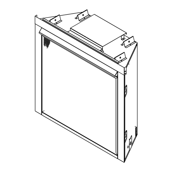
Page 54: Appliance Setup
Appliance Setup A. Remove the Packaging Remove the shrink fi lm, corrugated top cap, bottom cap and column protectors from the appliance. The appliance should look as shown in Figure 14.1. Figure 14.2 Open Access Flap Figure 14.1 Appliance Unwrapped B. -
Page 55: Place The Rockwool
G. Place the Rockwool J. Remove Screen Protector • Tear the corrugated as shown in Figure 14.6. The WARNING! Risk of Explosion! Follow rockwool place- corrugated must be separated along the entire top edge ment instructions. DO NOT place rockwool directly over of the protector. -
Page 56: Unpackage The Hood & Floor Cover
K. Unpackage the Hood & Floor Cover M. Install Floor Cover Remove the hood, fl oor cover and protective cardboard Install the fl oor cover as shown in Figure 14.10. from the back side of the screen as shown in Figure 14.8. Figure 14.10 Installing Floor Cover Note: The fl... -
Page 57: Close The Screen Assembly
P. Air Shutter Setting Replacing Fixed Glass Assembly • Set the glass panel on the lower two glass assembly This appliance has an adjustable air shutter (which latches, ensuring the glass panel is centered in the controls the primary air) that can be accessed under the opening. -
Page 58: Troubleshooting
Troubleshooting With proper installation, operation, and maintenance your gas appliance will provide years of trouble-free service. If you do experience a problem, this troubleshooting guide will assist a qualifi ed service technician in the diagnosis of a problem and the corrective action to be taken. This troubleshooting guide can only be used by a qualifi ed service technician. Con- tact your dealer to arrange a service call by a qualifi... - Page 59 Troubleshooting (continued) Symptom Possible Cause Corrective Action 3. (Continued) C. Failed valve. Turn the valve knob to the ON position. Place the ON/OFF switch in the ON position. Check the millivolt meter a the thermopile terminals. The millivolt meter should read greater than 125mV. If the reading is acceptable, and if the burner does not come on, replace the gas valve.
-
Page 60: Intellifi Re Ignition System
B. Intellifi re Ignition System Symptom Possible Cause Corrective Action 1. Pilot won’t light. The A. Incorrect wiring. Verify “S” wire (white) for sensor and “I” wire (orange) for ignitor are ignitor/module makes connected to correct terminals on module and pilot assembly. noise, but no spark. - Page 61 Intellifi re Ignition System - (continued) Symptom Possible Cause Corrective Action 4. Pilot lights but continues A. A shorted or loose connection Verify all connections to wiring diagram in manual. Verify to spark, and main burner in fl ame sensing rod. connections underneath pilot assembly are tight.
-
Page 62: Reference Materials
Reference Materials A. Appliance Dimension Diagram Dimensions are actual appliance dimensions. Use for reference only. For framing dimensions and clearances refer to Section 5. 11 1/2 in. (292 mm) 30 1/2 in. 27 in. (775 mm) (686 mm) 22 3/8 in. (568 mm) 5 1/2 in. -
Page 63: Vent Components Diagrams
B. Vent Components Diagrams Effective Height/Length 4-7/8 in. Pipe inches (124 mm) DVP4 10-1/2 in. DVP6 45° (267 mm) Effective DVP12 Height/Length DVP24 DVP36 DVP48 1219 DVP6A 3 - 6 76 - 152 10-7/8 in. DVP12A 3 - 12 76 - 305 (276 mm) DVP45 DVP Pipe... - Page 64 B. Vent Components Diagrams (continued) 31 in. (787 mm) 24-5/8 in. 13-1/4 in. (625 mm) (367 mm) 27-1/2 in. 24-5/8 in. 13-1/4 in. (698 mm) (625 mm) (367 mm) RF6M RF12M Roof Flashing Multi-pak Roof Flashing Multi-pak 13-3/4 in. 5 in. 11-7/8 in.
- Page 65 B. Vent Components Diagrams (continued) 7-3/8 in. (187 mm) 1-1/2 in. (38 mm) 17-3/4 in. PVK-80 14 in. (451 mm) (For use with IPI and DSI appliances only) (356 mm) 3-7/8 in. (98 mm) 12 in. (305 mm) 10-1/2 in. (267 mm) DVP-TB1 Basement Vent Cap...
- Page 66 B. Vent Components Diagrams (continued) Note: Heat shields MUST overlap by a minimum of 1-1/2 in. (38 mm). The heat shield is designed to be used on a wall 4 in. to 7-1/4 in. (102 mm to 184 mm) thick. If wall thickness is less than 4 in. (102 mm) the existing heat shields must be field trimmed.
- Page 67 B. Vent Components Diagrams (continued) 6-1/2 in. 165 mm 6-1/2 in. 165 mm 6-1/2 in. 165 mm 8-3/4 in. 9-1/4 in. 222 mm 6 in. 235 mm 152 mm 6-5/8 in. 168 mm 6-5/8 in. SLP-45 - 45° Elbow 168 mm 9-7/8 in.
- Page 68 B. Vent Components Diagrams (continued) SLK-SNKD SLP-CCS-BK SLP-TVHW Snorkel Cathedral Ceiling Sup- Vertical PVK-80 Termination Cap port Box-Black Termination Cap Power Vent SL-2DVP DVP-FBHT Adapter Firebrick Termination Cap (This termination cap requires an SL-2DVP adapter when used with SLP Pipe) 8-1/8 in.
-
Page 69: Service Parts
C. Service Parts Heatilator • AVEO Series DV • 4058-210 Rev F • 10/08... - Page 70 C. Service Parts (continued) Heatilator • AVEO Series DV • 4058-210 Rev F • 10/08...
- Page 71 C. Service Parts (continued) Heatilator • AVEO Series DV • 4058-210 Rev F • 10/08...
- Page 72 C. Service Parts (continued) Heatilator • AVEO Series DV • 4058-210 Rev F • 10/08...
- Page 73 C. Service Parts (continued) Heatilator • AVEO Series DV • 4058-210 Rev F • 10/08...
- Page 74 C. Service Parts (continued) Heatilator • AVEO Series DV • 4058-210 Rev F • 10/08...
-
Page 75: Optional Components
D. Optional Components Model Description ADVT3428 Top direct vent, natural gas, standing pilot ignition system, 34 in. framing width, 28 in. viewing glass ADVR3428 Rear direct vent, natural gas, standing pilot ignition system, 34 in. framing width, 28 in. viewing glass ADVT3428I Top direct vent, natural gas, Intellifi... -
Page 76: Contact Information
E. Contact Information Please contact your Heatilator dealer with any questions or concerns. For the location of your nearest Heatilator dealer, please visit www.heatilator.com. - NOTES - ________________________________________________________________________________ ________________________________________________________________________________ ________________________________________________________________________________ ________________________________________________________________________________ ________________________________________________________________________________ ________________________________________________________________________________ ________________________________________________________________________________ ________________________________________________________________________________ ________________________________________________________________________________ NOTICE DO NOT DISCARD THIS MANUAL •...
Need help?
Do you have a question about the Heatilator ADVT3428 and is the answer not in the manual?
Questions and answers