Heatilator A36R Installation Manual
Hide thumbs
Also See for A36R:
- Owner's manual (52 pages) ,
- Installation manual (40 pages) ,
- Owner's manual (52 pages)
Table of Contents
Advertisement
Quick Links
INSTALLER: Leave this manual with party responsible for use and operation.
OWNER: Retain this manual for future reference.
NOTICE: DO NOT discard this manual!
Model(s):
WOODBURNING FIREPLACE
Installation and service of this
appliance should be performed by
qualified personnel. Hearth & Home
Technologies recommends HHT
Factory Trained or NFI certified
professionals.
Heatilator • A36/42R, A36/42RH • Installers Manual • 4017-259 • Rev I • 06/29/15
Installation Manual
Installation and Fireplace Setup
WARNING: If the information in these
instructions is not followed exactly, a fire
or explosion may result causing property
damage, personal injury, or death.
• DO NOT store or use gasoline or other flam-
mable vapors and liquids in the vicinity of this
or any other appliance.
• DO NOT overfire. Overfiring will void your
warranty.
• Comply with all minimum clearances to com-
bustibles as specified. Failure to comply may
cause house fire.
WARNING
HOT SURFACES!
Glass and other surfaces are hot during
operation AND cool down.
Hot glass will cause burns.
• DO NOT touch glass until it is cooled
• NEVER allow children to touch glass
• Keep children away
• CAREFULLY SUPERVISE children in same room as
fireplace.
• Alert children and adults to hazards of high temperatures.
High temperatures may ignite clothing or other flammable
materials.
• Keep clothing, furniture, draperies and other flammable
materials away.
WARNING
Fire Risk.
For use with solid wood fuel only.
Other fuels may overfire and generate
poisonous gases (i.e. carbon monoxide).
1
Advertisement
Table of Contents

Related Manuals for Heatilator A36R


Summary of Contents for Heatilator A36R
- Page 1 Technologies recommends HHT For use with solid wood fuel only. Factory Trained or NFI certified Other fuels may overfire and generate professionals. poisonous gases (i.e. carbon monoxide). Heatilator • A36/42R, A36/42RH • Installers Manual • 4017-259 • Rev I • 06/29/15...
-
Page 2: Table Of Contents
C. Secure Offset/Return D. Install Ceiling Firestops E. Install Attic Insulation Shield F. Roof Penetration G. Install Chase/Chase Top H. Termination Cap Requirements I. Install Termination Cap Heatilator • A36/42R, A36/42RH • Installers Manual • 4017-259 • Rev I • 06/29/15... - Page 3 Comments: Further description of the issues, who is responsible (Installer/Builder/Other Trades, etc.) and corrective action needed: Comments communicated to party responsible __________________________ by ______________________on _________ (Builder/Gen. Contractor) (Installer) (Date) 4017-261 • Rev A • 2-19-13 Heatilator • A36/42R, A36/42RH • Installers Manual • 4017-259 • Rev I • 06/29/15...
-
Page 4: Product Specific & Important Safety Information
Improper installation, adjustment, alteration, service or maintenance can cause injury or property damage. For assistance or additional information, consult a qualified installer, service agency or your dealer. Heatilator • A36/42R, A36/42RH • Installers Manual • 4017-259 • Rev I • 06/29/15... -
Page 5: Getting Started
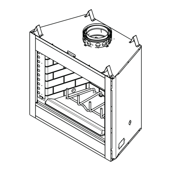
4 ft. Decorative facing (1.22 m) off and trim ground level. Hearth extension Outside combustion air Factory-built fireplace Protective metal hearth strip(s) Figure 2.1 Typical Fireplace System Heatilator • A36/42R, A36/42RH • Installers Manual • 4017-259 • Rev I • 06/29/15... -
Page 6: Design And Installation Considerations
Minimum from FP 1295 1092 1902 1346 opening to any 77 1/2 38 7/8 54 7/8 perpendicular wall. 1448 1245 1969 1394 Figure 2.2 Fireplace Locations Heatilator • A36/42R, A36/42RH • Installers Manual • 4017-259 • Rev I • 06/29/15... -
Page 7: Locating Fireplace & Chimney
• Below adjacent structure Recommended: • Lower roof line • Insulated exterior chase in cooler climates • Avoid outside wall Windward Leeward Multi-level Roofs Figure 2.3 Recommended Chimney Locations Heatilator • A36/42R, A36/42RH • Installers Manual • 4017-259 • Rev I • 06/29/15... -
Page 8: Tools And Supplies Needed
Report to your dealer any parts damaged in shipment. • Read all the instructions before starting the installation. Follow these instructions carefully during the installation to ensure maximum safety and benefit. Heatilator • A36/42R, A36/42RH • Installers Manual • 4017-259 • Rev I • 06/29/15... -
Page 9: Framing And Clearances
(108 mm) (191 mm) (108 mm) 13-1/2 in. 13-1/2 in. (343 mm) (343 mm) Model # 28-1/4 14-1/8 1067 30-7/8 15-1/2 1067 1219 Figure 3.1 Fireplace Dimensions Heatilator • A36/42R, A36/42RH • Installers Manual • 4017-259 • Rev I • 06/29/15... -
Page 10: Clearances
(except at nailing flanges 48 in. where it is 1/2 in. [13 mm]) 1219 mm 0 in. to floor Figure 3.2 Clearances to Combustible Materials Heatilator • A36/42R, A36/42RH • Installers Manual • 4017-259 • Rev I • 06/29/15... -
Page 11: Construct The Chase
In cold climates, the walls of the chase should be insulated to the level of the false ceiling as shown in Figure 3.3. This will help reduce heat loss from the home around the fireplace. Heatilator • A36/42R, A36/42RH • Installers Manual • 4017-259 • Rev I • 06/29/15... -
Page 12: Frame The Fireplace
* If interior of chase will be drywalled, add the thickness to this measurement. ** Adjust header height for a raised floor under fireplace. Figure 3.5 Framing the Fireplace Heatilator • A36/42R, A36/42RH • Installers Manual • 4017-259 • Rev I • 06/29/15... -
Page 13: Protective Metal Hearth Strips
Figure 3.6. See Section 7 for hearth extension Floor instructions. 2 in. (51 mm) Nail or screw metal strips in place. Figure 3.7 Protect the Front of an Elevated Platform Heatilator • A36/42R, A36/42RH • Installers Manual • 4017-259 • Rev I • 06/29/15... -
Page 14: Outside Air Kit (Optional)
• Secure flex duct with screws or wire ties. Figure 3.9 Outside Air Installation Heatilator • A36/42R, A36/42RH • Installers Manual • 4017-259 • Rev I • 06/29/15... -
Page 15: Chimney And Termination Requirements
16.5 ft (5.03 m) min. height/single offset-return (1051 mm) 20 ft. (6.10 m) min. height/double offset-return Effective 90 ft (27.4 m) max. height Height Figure 4.1 Chimney Requirements Heatilator • A36/42R, A36/42RH • Installers Manual • 4017-259 • Rev I • 06/29/15... -
Page 16: Offsets/Returns
103 1/2 2629 49 1/4 1251 94 1/2 2400 Proper assembly of air-cooled chimney parts result in an overlap at chimney joints of 1-1/4 in. (32 mm). Effective length is built into this chart. Heatilator • A36/42R, A36/42RH • Installers Manual • 4017-259 • Rev I • 06/29/15... -
Page 17: Termination Requirements
In a staggered installation with both gas and wood terminations, the wood termination cap must be higher than the gas termination cap. Figure 4.3 Multiple Chimney Locations Heatilator • A36/42R, A36/42RH • Installers Manual • 4017-259 • Rev I • 06/29/15... -
Page 18: Chimney Installation
Ceiling firestops are required where chimney passes through ceiling or floor Figure 5.1 Typical Chimney System - Guidelines for Chimney System Installation Heatilator • A36/42R, A36/42RH • Installers Manual • 4017-259 • Rev I • 06/29/15... -
Page 19: Assemble Chimney Sections
Vertical straight runs of chimney must be supported every 35 ft (10.7 m). Figure 5.2 Assembling Chimney Sections WARNING! Risk of Fire! DO NOT install substitute or damaged chimney components. Heatilator • A36/42R, A36/42RH • Installers Manual • 4017-259 • Rev I • 06/29/15... -
Page 20: Secure Offset/Return
• Use an attic insulation shield if the ceiling is insulated. The ceiling firestop may then be attached above or below the joists. Heatilator • A36/42R, A36/42RH • Installers Manual • 4017-259 • Rev I • 06/29/15... -
Page 21: Install Attic Insulation Shield
If they have been connected correct- Ceiling Firestop Pipe (267 mm) ly, they will not disengage when tested. Figure 5.7 Install Attic Insulation Shield (firestop below ceiling) Heatilator • A36/42R, A36/42RH • Installers Manual • 4017-259 • Rev I • 06/29/15... -
Page 22: Roof Penetration
WARNING! Risk of Fire! DO NOT caulk the pipe to the chase top collar. • Caulk all seams to prevent leaks. .018 (26 ga) min. Galvanized Chase Top Figure 5.9 Chase Top Construction Heatilator • A36/42R, A36/42RH • Installers Manual • 4017-259 • Rev I • 06/29/15... -
Page 23: Termination Cap Requirements
Termination cap pipe and chimney section must be snapped together to maintain an overlap of 1-1/2 in. (38 mm). Figure 5.10 Installing a TR344 Round Termination Cap Heatilator • A36/42R, A36/42RH • Installers Manual • 4017-259 • Rev I • 06/29/15... - Page 24 Minimum Height Maximum Chase Top Chase Chimney Pipe Termination cap pipe and chimney section must overlap 1-1/2 in. (38 mm) Figure 5.15 Installing a DTO134/DTO146/DTS134/DTS146 Cap Heatilator • A36/42R, A36/42RH • Installers Manual • 4017-259 • Rev I • 06/29/15...
-
Page 25: Shrouds
3 in (76 mm) air space from bottom of shroud Chase Top to top of chase. Figure 6.3 Shroud & TR Series cap with no Radiation Shield Heatilator • A36/42R, A36/42RH • Installers Manual • 4017-259 • Rev I • 06/29/15... -
Page 26: Mailbox Style Shroud
TR342/344TV Min. Base Dims. Min. Opening Width 27 x 27 686 x 686 Min. Height Above Bottom of Termination Cap Min. Opening Width Min. Opening Height Heatilator • A36/42R, A36/42RH • Installers Manual • 4017-259 • Rev I • 06/29/15... -
Page 27: Finishing
2 in. (51 mm) Figure 7.2 Decorative Facing Heatilator • A36/42R, A36/42RH • Installers Manual • 4017-259 • Rev I • 06/29/15... -
Page 28: Hearth Extension, Building And Finishing
2.18 1/2 in. • Choose finishing materials carefully. 14-5/8 in. - 20-3/8 Marble 14.3-20.0 0.07-0.05 Hearth Extension Dimensions Model # (HX3) 1321 (HX4) 1676 Figure 7.3 Hearth Extension Dimensions Heatilator • A36/42R, A36/42RH • Installers Manual • 4017-259 • Rev I • 06/29/15... -
Page 29: Fireplace Installed Flush On The Floor And Hearth Extension Raised To Bottom Of Firebox Opening
NOT extend above this level. in front of and 8 in. (203 mm) to each side of fireplace opening of the A36R 20 in. (508 mm) in front and 12 in. (305 mm) to each side of the A42R is required. -
Page 30: Raised Hearth Extension And Raised Fireplace
Protective Metal Hearth Strips Non-combustible Floor and platform constructed of Framing Material wood or other combustible material Figure 7.8 Raised Hearth Extension and Fireplace Framing Materials Heatilator • A36/42R, A36/42RH • Installers Manual • 4017-259 • Rev I • 06/29/15... -
Page 31: Fireplace Opening And Hearth Extension Flush With The Floor
Hearth & Home Technologies is not responsible for discoloration, cracking or other material failures of finishing materials due to heat exposure or smoke. Micore Noncombustible Material Protective Metal • Choose finishing materials carefully. Hearth Strip Figure 7.9 Flush Hearth Extension Side View Heatilator • A36/42R, A36/42RH • Installers Manual • 4017-259 • Rev I • 06/29/15... -
Page 32: Mantel And Wall Projections
Decorative Facing Measured from top of fireplace opening such as: Steel, iron, brick, tile, concrete, slate, Grid represents 1 in. squares glass, plasters. Figure 7.12 Mantel Specifications Heatilator • A36/42R, A36/42RH • Installers Manual • 4017-259 • Rev I • 06/29/15... -
Page 33: Sidewalls/Surrounds
9 3/4 in. [248 mm] 12 in. 12 in. [305 mm] [305 mm] Figure 7.13 Mantel Leg, Surround or Wall Projection (acceptable on both sides of opening) Heatilator • A36/42R, A36/42RH • Installers Manual • 4017-259 • Rev I • 06/29/15... -
Page 34: Fireplace Setup
• Hearth & Home Technologies recommends securing the reline at the top of the flue and using the cap certified for use with this fireplace system. Heatilator • A36/42R, A36/42RH • Installers Manual • 4017-259 • Rev I • 06/29/15... -
Page 35: Reference Materials
Adapter - May be used with the following caps Outside CT Series 4-3/4 in. (121 mm) Diameter DT Series Effective Height 10-1/2 in. (267 mm) SL3 Chimney Stabilizer Heatilator • A36/42R, A36/42RH • Installers Manual • 4017-259 • Rev I • 06/29/15... - Page 36 (625 mm) (787 mm) 10-1/2 in. (267 mm) RF371 Roof Flashing CB876 Chimney Joint Band 7 3/4 in. 26 in. TR-TVK TR Top Vent Kit CT-3A Heatilator • A36/42R, A36/42RH • Installers Manual • 4017-259 • Rev I • 06/29/15...
- Page 37 TR342 Round Telescoping Termination Cap 9 1/2 in. 23 in. (241 mm) (584 mm) 19 in. (483 mm) TCT375 Terra Cotta Cap 15-5/8 in. (397 mm) ST375 Square Termination Cap Heatilator • A36/42R, A36/42RH • Installers Manual • 4017-259 • Rev I • 06/29/15...
- Page 38 22 3/4 in. 21 3/16 in. (577 mm) (538 mm) 46 in. 46 in. (1168 mm) (1168 mm) 26 in. 26 in. (660 mm) (660 mm) DTO146 DTS146 Heatilator • A36/42R, A36/42RH • Installers Manual • 4017-259 • Rev I • 06/29/15...
-
Page 39: Optional Components
UD4 Uninsulated Duct 12.5 15.5 LDS-BV 4 in. (102 mm) i.d. 42 in. (1067 mm) See your Heatilator dealer for a complete list of optional components. Heatilator • A36/42R, A36/42RH • Installers Manual • 4017-259 • Rev I • 06/29/15... - Page 40 7571 215th Street West, Lakeville, MN 55044 www.heatilator.com Please contact your Heatilator dealer with any questions or concerns. For the location of your nearest Heatilator dealer, please visit www.heatilator.com. Heatilator • A36/42R, A36/42RH • Installers Manual • 4017-259 • Rev I • 06/29/15...
Need help?
Do you have a question about the A36R and is the answer not in the manual?
Questions and answers