Table of Contents
Advertisement
User's Guide
UHF
The Sound of Professionals...Worldwide
Shure Brothers Incorporated
222 Hartrey Avenue, Evanston, Illinois 60202–3696 Phone: 847/866–2200 Fax: 847/866-2279
In Europe, Phone: 49-7131-72140 Fax: 49-7131-721414 Internationally, Phone: 847/866–2200 Fax: 847/866-2585
27A8571 (RA)
Copyright 1998, Shure Brothers Incorporated
Printed in U.S.A.
Advertisement
Table of Contents

Related Manuals for Shure U Series


Summary of Contents for Shure U Series
- Page 1 User’s Guide The Sound of Professionals...Worldwide Shure Brothers Incorporated 222 Hartrey Avenue, Evanston, Illinois 60202–3696 Phone: 847/866–2200 Fax: 847/866-2279 In Europe, Phone: 49-7131-72140 Fax: 49-7131-721414 Internationally, Phone: 847/866–2200 Fax: 847/866-2585 27A8571 (RA) Copyright 1998, Shure Brothers Incorporated Printed in U.S.A.
-
Page 2: Table Of Contents
ENGLISH ENGLISH TABLE OF CONTENTS SYSTEM DESCRIPTION ............SYSTEM FEATURES . -
Page 3: System Description
ENGLISH SYSTEM DESCRIPTION The Shure UHF Wireless microphone system is a frequency-agile diversity sys- tem operating in the UHF band. Both the receiver and the transmitter are synthesizer controlled via Phase Locked Loop (PLL) circuitry for clear, steady radio frequency (RF) signal. - Page 4 3. Input Connector: Provides connection with a variety of lavalier and headset mi- crophone cables, and the Shure WA302 instrument adapter cable. LEMO–type connectors are available as an option. 4. ON/OFF Switch: Turns transmitter power on and off.
- Page 5 ENGLISH ENGLISH 1. Grille. Protects the microphone cartridge and helps reduce breath sounds and wind noise. The grilles for the various microphone heads differ in appearance. 2. Programmable Display: Displays Group and Channel, battery power level, and frequency lock/power lock on/off status. 3.
-
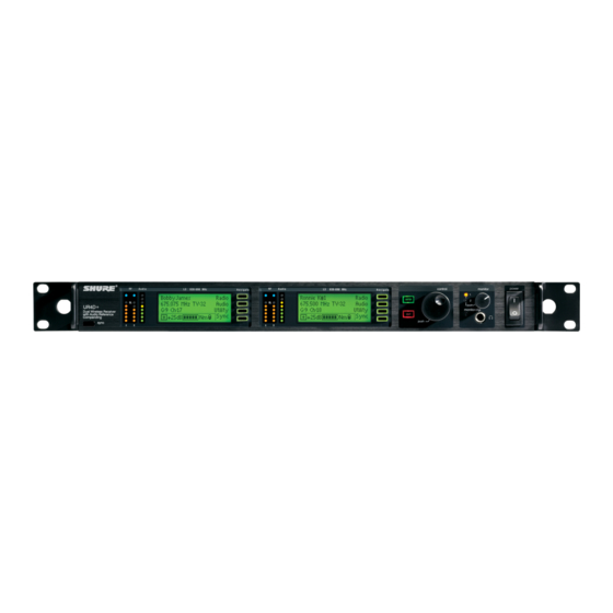
Page 6: U4S & U4D Receiver Controls & Connectors
Hz power source. 14. Power Output Connector: Provides 90 to 230 VAC, 50/60 Hz power to additional 16 17 equipment. It can be used to link multiple receivers or to power the Shure UA840 Antenna Distribution System. U4D Receiver 15. Antenna Input Connectors: BNC-type connectors provide connection to the... -
Page 7: Receiver Setup
(TOP VIEW) FIGURE 7 NOTE: Shure recommends connecting the bulkhead adapter and antenna cables before mounting the receiver in a rack. Once the receiver is in the rack, it is more diffi- cult to insert the bulkhead adapters and connect the antenna cables. -
Page 8: Basic Receiver Connections
ENGLISH ENGLISH Basic Receiver Connections (Figure 10) 3. Connect the female end of a modular power cord to the male power input connec- tor on the rear panel of the receiver. Then plug the power cord into a suitable AC 1. -
Page 9: Changing Receiver Frequency Setting
ENGLISH ENGLISH 4. Press the “SELECT” button to choose Group or Channel. The current Group, Changing Receiver Frequency Setting Channel, and TV channel setting will appear, as shown in Figure 13. (Models sold 1. Press the MENU button. The + MENU – display will appear, as shown in Figure 16. outside the U.S. -
Page 10: Changing Receiver Name
FIGURE 22 3. Press the SELECT button. An underline will appear under the first character of the name. The factory pre–set Name display (SHURE) is shown in Figure 23. FIGURE 26 3. Press the SELECT button to display the current squelch level, as shown in Figure 27 (factory preset value is “0.0”). -
Page 11: Locking The Receiver Display
ENGLISH ENGLISH NOTE: The highest possible squelch setting is +10.0 and the lowest possible 5. Once you have reached the desired squelch level, press the MENU button. squelch setting is –10.0, as shown in the following table . However, the factory SAVE? will appear, followed by + YES –... -
Page 12: Unlocking The Receiver Display
ENGLISH ENGLISH 3. Press the SELECT button. The CODE? display will appear, as shown in Figure 31. TRANSMITTER SETUP Transmitter Battery Installation (Figure 34) 1. Make sure the transmitter power ON/OFF switch is in the OFF position. 2. Open the transmitter battery compartment as follows: U1 Transmitter: Squeeze the two tabs on either side of the transmitter and flip the battery cover down. -
Page 13: Checking Transmitter Batteries
ENGLISH ENGLISH Checking Transmitter Batteries (Figure 35) Connecting a Lavalier Microphone or Instrument Cable to the U1 Transmitter (Figure 36) 1. Turn the transmitter power ON/OFF switch to the ON position. 1. Plug the microphone cable or instrument cable into the transmitter input connector. 2. - Page 14 ENGLISH ENGLISH 3. Press and hold down the MODE button until only the Group number is displayed, 5. Press the MODE button again so that only the Channel number is displayed, as as shown in Figure 38. shown in Figure 40. FIGURE 40 FIGURE 38 6.
-
Page 15: Locking The Power Switch In The On Position
ENGLISH ENGLISH Locking the Power Switch in the ON Position Activating the Frequency Lock Function To lock the power switch, press and hold the SET button, then press and hold the The Frequency Lock function prevents accidental frequency changes, and is par- MODE button. -
Page 16: Cancelling The Frequency Lock Function
ENGLISH ENGLISH NOTE: When the Frequency Lock function is engaged, the Power On Lock func- 5. Turn the receiver on by pressing the upper section of the POWER switch. The re- ceiver display and RF LEDs will glow. tion can still be activated. However, if the Power Lock and the Frequency Lock functions are engaged, the Power Lock function must be disengaged before the 6. -
Page 17: Adjusting Transmitter Audio Gain Level
(see Figure 47). ommended. 4. Orient the belt clip so that “Shure” is on the outside and toward the top (antenna If you are using the Shure WH10TQG headset, rotate the gain control to the full side) of the transmitter. -
Page 18: Tips For Achieving Optimum Performance
TROUBLESHOOTING Some common problems and their solutions are identified in the table below. If you are unable to solve a problem, contact your dealer or the Shure Service Department SPECIFICATIONS at 1-800-516-2525 (7:30 am to 4:00 pm, Central Standard Time). In Europe, call 49-7131-72140;... -
Page 19: Appendix: Network Interface Pin Map
RF level, and ‘’A/B” diversity indication, from a remote Diversity A Analog Output 1–4 V location via an interface device. The table below identifies the signal output by each pin on the connector. Contact you Shure dealer for addition information. Serial Clock Digital Input 1–4 V Applicable NOTE: Using any of the pins in the shaded area could result in system mal- function or damage to your receiver.
Need help?
Do you have a question about the U Series and is the answer not in the manual?
Questions and answers