Shure U4D Service Manual
Dual diversity uhf receiver
Hide thumbs
Also See for U4D:
- User manual (19 pages) ,
- Programming manual (2 pages) ,
- Programming manual (2 pages)
Table of Contents
Advertisement
SERVICE MANUAL CHANGE NOTICE
UHF WIRELESS RECEIVER MODEL U4D
Changes and corrections have been made to the Service Manual for the U4D UHF Wireless Receiver.
These changes will make it easier to properly align the receivers. To update your Service Manual, remove
the pages identified in the tables below and replace them with the pages attached to this Change Notice.
Note that there are no changes to pages not specifically identified in the tables below.
U4D SERVICE MANUAL REVISION HISTORY
Release
Original
Revision 1
Revision 2
Revision 3
Revision 4
Revision 5
CHANGES EFFECTIVE JULY, 2001
REMOVE
these pages from the U4D Service Manual
E2000, Shure Incorporated
25–1062–2 (TD)
35–40
Shure Brothers Incorporated
222 Hartrey Avenue
Evanston IL 60202-3696 U.S.A.
UHF Wireless System
Part Number
25A1062
25B1062
25C1062
25D1062
25D1062
25D1062
these Revisionpages into the U4D Service Manual
Date Code
QE
QK
SB
TD
TL
AG
INSERT
35–40
Printed in U.S.A.
Advertisement
Table of Contents

Related Manuals for Shure U4D


Summary of Contents for Shure U4D
- Page 1 SERVICE MANUAL CHANGE NOTICE UHF WIRELESS RECEIVER MODEL U4D Changes and corrections have been made to the Service Manual for the U4D UHF Wireless Receiver. These changes will make it easier to properly align the receivers. To update your Service Manual, remove the pages identified in the tables below and replace them with the pages attached to this Change Notice.
-
Page 2: Controls And Connectors
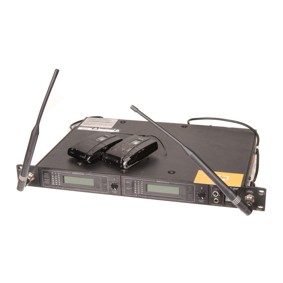
U4D Dual Diversity UHF Receiver General Characteristics The Shure Model U4D Dual Diversity UHF Receiver is a microprocessor con- trolled dual diversity receiver operating in the UHF frequency range. This product is intended for use in high-end installed sound, rental, and concert sound mar- kets. -
Page 3: Circuit Description
Shure U4D Dual Diversity UHF Receiver Circuit Description Power Section The receiver accepts power line voltage ranging from 85 Vac to 264 Vac. The receiver hardware uses the +5 Vdc, +12 Vdc and 12 Vdc volt- ages from the switching power supply. The switching power supply has 40 W overall output power capability, with maximum current capabilities of 4A at 5V, 2A at +12V, and .5A at –12V. -
Page 4: Local Oscillator
Shure U4D Dual Diversity UHF Receiver ond mixer. The second down–converter also incorporates an internal IF amplifier that is used with external 10.7 MHz ceramic filters. The 10.7 MHz signal goes to the second IF gain block with detector. The audio output is buffered with an operational amplifier, then processed as de- scribed in the Audio section. - Page 5 Shure U4D Dual Diversity UHF Receiver compared to an adjustable squelch level (a dc level). If either channel’s noise is greater than the squelch threshold, its switch is shut off. The outputs from the analog switches are connected at the audio combining stage.
-
Page 6: Microcontroller Section
Shure U4D Dual Diversity UHF Receiver the LEDs. The output from this stage drives the audio level meter on the front panel board. A dc voltage from the detector chip RSSI drives the bar graph integrated circuit on the front board for the rf level meters. - Page 7 Shure U4D Dual Diversity UHF Receiver User Interface Section The user interface section consists of switches SW101 MENU, SW103 SELECT, SW102 UP (+), and SW104 DOWN (–). These switches provide access to various user-programmable menus on the front panel display. The LCD provides the user with feedback for all switch actions performed.
- Page 8 Shure U4D Dual Diversity UHF Receiver Display Board Interconnect with Rf-Audio Board Integrated ribbon cable connector P102 interfaces with the rf-audio board and the networking Interface board through the display board. Pin assignments for the P102 connector are presented in the table below.
- Page 9 Shure U4D Dual Diversity UHF Receiver Notes This page intentionally left blank. 25D1062 (AG) Notes...
-
Page 10: Preliminary Tests
Shure U4D Dual Diversity UHF Receiver Preliminary Tests Test Component Locations Rf-Audio Board, Side 1 Preliminary Tests 25D1062 (AG) - Page 11 Shure U4D Dual Diversity UHF Receiver Audio-Rf Board, Side 2 25D1062 (AG) Preliminary Tests...
-
Page 12: Listening Test
Shure U4D Dual Diversity UHF Receiver Listening Test Before completely disassembling the receiver, operate it to determine whether it is functioning normally and try duplicating the reported malfunc- tion. Refer to the User Guide for operating instructions, troubleshooting suggestions, and specifications. - Page 13 Shure U4D Dual Diversity UHF Receiver 8. Make sure the tone key switch (S201) on the receiver rf-audio board is in the ON position.The receiver should be muted. No audio output should be present at the balanced and unbalanced outputs.
-
Page 14: Disassembly And Assembly
Voltages in this equipment are hazardous to life. No user-serviceable parts are inside. Refer all servicing to qualified service personnel. The safety certifications of the U4D Dual Diversity Receiver do not apply when the operating voltage is changed from the factory setting. -
Page 15: Front Panel Removal
Shure U4D Dual Diversity UHF Receiver Front Panel Removal 1. Remove the three screws securing the brace and the rf shielding gaskets to the chassis, then remove the brace. 2. Remove the hexnuts and star washers securing the front panel to the inside of the front chassis. -
Page 16: Power Supply Removal
Shure U4D Dual Diversity UHF Receiver Printed Circuit Board (PCB) Removal Rf-Audio Board Removal 1. Tag and disconnect the cables attached to the pcbs. Standard cable connections are shown in Figure 3. 2. Remove the screws and washers that secure the rf-audio pcb to the receiver chassis, then lift the board out. - Page 17 Shure U4D Dual Diversity UHF Receiver NETWORK INTERFACE BOX ANTENNA B ANTENNA A AC POWER INPUT RECEIVER 2 RECEIVER 1 NETWORK BOARD DC POWER SUPPLY TO NET TO NET BOARD TO DISPLAY TO MONITOR BOARD TO DISPLAY TO MONITOR BOARD...
-
Page 18: Service Procedures
Shure U4D Dual Diversity UHF Receiver Service Procedures Product Changes The following changes have been made to the U4D receiver. New Volume Control Knobs and Potentiometers The new potentiometers cannot be used on old boards, and the new knob assembly cannot be used with old potentiometers. -
Page 19: Test Equipment
Shure U4D Dual Diversity UHF Receiver Test Equipment Most test equipment needed is described in the Shure Wireless Service Equipment Manual. The following test equipment (or approved equivalent) is also needed. Table 2 Test Equipment Equipment Type Model Audio analyzer... -
Page 20: Test Setup
Equipment setup for the alignment procedure is sequential. Test Setup 1. Remove the top cover from the U4D receiver. 2. To reduce the risk of electrical shock, do not touch or short any components in the receiver switching power supply. The heat sink on the power supply and all ac wiring contains hazardous voltages. - Page 21 1. Turn the U4D receiver power ON. 2. Connect the U4D receiver antennas. 3. Program the U4D receiver to any clean frequency in the area, using the SET FREQ menu on the display. To do this, select a television channel that is inactive in the area, and then scan for a frequency at which the yellow rf LEDs are not lit.
-
Page 22: Dc Voltage Verification
Shure U4D Dual Diversity UHF Receiver Rf Tuning, Channel A Dc Voltage Verification DC VOLTMETER DC VOLTMETER ANTENNA A IN ANTENNA B IN S201 S201 (OFF) (OFF) C242 C227 P202 P202 P202 P203 P202 P203 J302 Figure 5. Dc Voltage Level Verification 1. - Page 23 Shure U4D Dual Diversity UHF Receiver Local Oscillator Frequency Alignment (Channel A) ANTENNA A IN ANTENNA B IN S201 S201 (OFF) (OFF) P202 P202 P202 P202 P203 P203 VC101 U308 TPRF6 PIN 1 J302 FREQUENCY COUNTER CH 2 CH 1 Figure 6.
- Page 24 Shure U4D Dual Diversity UHF Receiver FM Detector Quadrature Coil Alignment (Channel A) RF SIGNAL GENERATOR NOTE: DC VOLTAGES ARE PRESENT AT MOST RF TEST POINTS. USE A DC BLOCK ON THE RF SIGNAL GENERATOR TO PROTECT TEST EQUIPMENT. DC BLOCK...
- Page 25 Shure U4D Dual Diversity UHF Receiver Second Mixer Coil Alignment (Channel A) RF SIGNAL GENERATOR NOTE: DC VOLTAGES ARE PRESENT AT MOST RF TEST POINTS. USE A DC BLOCK ON THE RF SIGNAL GENERATOR TO PROTECT TEST EQUIPMENT. DC BLOCK...
- Page 26 Shure U4D Dual Diversity UHF Receiver THD Verification and RSSI Adjustment (Channel A) RF SIGNAL GENERATOR NOTE: DC VOLTAGES ARE PRESENT AT MOST RF TEST POINTS. USE A DC BLOCK ON THE RF SIGNAL GENERATOR TO PROTECT TEST EQUIPMENT. DC BLOCK...
- Page 27 Shure U4D Dual Diversity UHF Receiver Noise Set-Up (Channel A) The Noise Setup procedure aligns each channel so that for a given signal-to-noise ratio, the respective dc levels match. RF SIGNAL GENERATOR NOTE: DC VOLTAGES ARE PRESENT AT MOST RF TEST POINTS. USE A DC...
- Page 28 Shure U4D Dual Diversity UHF Receiver FM Detector Quadrature Coil Alignment (Channel B) RF SIGNAL GENERATOR DC BLOCK ANTENNA A IN ANTENNA B IN S201 S201 (OFF) (OFF) P202 P202 P202 P203 P202 P203 TP308 U310 L304 for PCB 34A8507...
- Page 29 Shure U4D Dual Diversity UHF Receiver Second Mixer Coil Adjustment (Channel B) RF SIGNAL GENERATOR NOTE: DC VOLTAGES ARE PRESENT AT MOST RF TEST POINTS. USE A DC BLOCK ON THE RF SIGNAL GENERATOR TO PROTECT TEST EQUIPMENT. DC BLOCK...
- Page 30 Shure U4D Dual Diversity UHF Receiver THD Verification and RSSI Adjustment (Channel B) RF SIGNAL GENERATOR DC BLOCK ANTENNA A IN ANTENNA B IN S201 S201 (OFF) (OFF) DC VOLTMETER P202 P202 P202 P202 P203 P203 TP308 U310 L304 for PCB...
- Page 31 Shure U4D Dual Diversity UHF Receiver Noise Setup (Channel B) The Noise Setup procedure aligns each Channel so that for a given signal-to-noise ratio, the respective dc levels match. DC VOLTMETER NOTE: DC VOLTAGES ARE PRESENT AT MOST RF TEST POINTS. USE A DC...
- Page 32 Shure U4D Dual Diversity UHF Receiver Audio Level Setup, Channel B RF SIGNAL GENERATOR DC BLOCK ANTENNA A IN ANTENNA B IN AUDIO ANALYZER S201 S201 (OFF) (OFF) U207 PIN 7 R250 P202 P202 P202 P202 P203 P203 NOTE: DC VOLTAGES ARE PRESENT AT MOST RF TEST POINTS.
- Page 33 Shure U4D Dual Diversity UHF Receiver Audio Level Setup, Channel A ANTENNA A IN ANTENNA B IN RF SIGNAL GENERATOR S201 S201 (OFF) (OFF) DC BLOCK U207 R203 PIN 7 P202 AUDIO ANALYZER P202 P203 P202 P202 P203 NOTE: DC VOLTAGES ARE PRESENT AT MOST RF TEST POINTS.
- Page 34 Shure U4D Dual Diversity UHF Receiver Tone Key Filter Alignment Reinstall the antennas for the Tone Key Filter Alignment procedure. ANTENNA B IN ANTENNA A IN DC VOLTMETER S201 S201 (ON) (ON) VC102 PIN 8 U208 P202 P202 P202 P202...
- Page 35 Shure U4D Dual Diversity UHF Receiver U4D Receiver 2 Alignment The Receiver 2 alignment procedure is identical to the Receiver 1 alignment procedure. However, for the Receiver 2 alignment procedure refer to Antenna B alignment procedures each time Antenna A is called out and refer to Antenna A procedures each time Antenna B is called out.
-
Page 36: Parts Designations
Replacement Parts and Drawings U4D Model Variations Different frequency versions of the U4D receiver are currently available for use in various countries. Each version is identified in the table below by country code, frequency range, and printed circuit board version. - Page 37 Shure U4D Dual Diversity UHF Receiver Table 4 U4D Receiver Replacement Parts Reference Designation Description Shure Part Number Ac ground wire assembly 90A8677 Ac wire assembly (brown) 90A8678 Ac wire assembly (blue) 90B8678 BNC cable assembly (13–inch) 95C8418 BNC cable assembly, mini pin (17 3/4–inch)
- Page 38 Shure U4D Dual Diversity UHF Receiver U4D Receiver Replacement Parts (Continued) Reference Designation Description Shure Part Number MP25 Daisy chain power cord 95A8576 MP26 AC ground wire 90A8677 MP27 Standoff 80A8094 MP28 Cover 53B8433 MP29 Antenna UA820A Table 5 Digital Display Printed Circuit Board Replacement Parts,...
- Page 39 Shure U4D Dual Diversity UHF Receiver Table 8 Network Interface Printed Circuit Board Replacement Parts, Non-SMT Components, Side 1 Reference Designation Description Shure Part Number P201, 202 Header, dual row 95A8660 P203 Header, single row, 5 position 95A8659 Table 9...
- Page 40 Shure U4D Dual Diversity UHF Receiver Table 11 RF–Audio Printed Circuit Board Replacement Parts, SMT Components, Side 1 Reference Designation Description Shure Part Number D201,202, 203, 204, 205, 210 SMD, switching diode 184A08 F300, 301 Polyswitch, SMD fuse 187A05 FL340, 341...
- Page 41 Shure U4D Dual Diversity UHF Receiver Table 13 VCO Selection Country Code UA205 VCO Range Shure Part Number 824–849 MHz 187A04 837–863 MHz 187B04 800–830 MHz 187C04 692–716 MHz 187D04 824–849 MHz 187A04 25D1062 (AG) Replacement Parts and Drawings...
- Page 42 Shure U4D Dual Diversity UHF Receiver SIDE 1 SIDE 2 Figure 18. Digital Display Printed Circuit Board Legend Replacement Parts and Drawings 25D1062 (AG)
- Page 43 Shure U4D Dual Diversity UHF Receiver Figure 19. Headphone Monitor Printed Circuit Board Legend 25D1062 (AG) Replacement Parts and Drawings...
- Page 44 Shure U4D Dual Diversity UHF Receiver SIDE 1 SIDE 2 Figure 20. Network Interface Printed Circuit Board Legend Replacement Parts and Drawings 25D1062 (AG)
- Page 45 Shure U4D Dual Diversity UHF Receiver Notes This page intentionally left blank. 25D1062 (AG) Notes...
- Page 46 Shure U4 UHF Diversity Receiver U4 Rf-Audio Printed Circuit Board Legend (Side 1) 25D1062 (TL)
- Page 47 Shure U4 Diversity UHF Receiver U4 Rf-Audio Printed Circuit Board Legend (Side 2) 25D1062 (TL)
Need help?
Do you have a question about the U4D and is the answer not in the manual?
Questions and answers