Table of Contents
Advertisement
SERVICE MANUAL CHANGE NOTICE
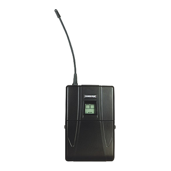
U1/U1L UHF BODY-PACK TRANSMITTER
Changes and corrections have been made to the Service Manual for the U1/U1L UHF Body-Pack Trans-
mitter. These changes will make it easier to repair the transmitters. To update your Service Manual,
remove the pages identified in the tables below and replace them with the pages attached to this Change
Notice. Note that there are no changes to pages not specifically identified in the tables below.
U1/U1L SERVICE MANUAL REVISION HISTORY
Release
Original
Revision 1
Revision 2
Revision 3
Revision 4
Revision 5
CHANGES EFFECTIVE JULY 12, 2002
REMOVE
these pages from the
U1/U1L Service Manual
21 to 25
E 2000, Shure Incorporated
25–1021–2 (BG)
Shure Incorporated
222 Hartrey Avenue
Evanston IL 60202-3696 U.S.A.
UHF Wireless System
Part Number
25A1021
25B1021
25C1021
25C1021
25C1021
25C1021
these Revised pages into the
U1/U1L Service Manual
Date Code
QE
SA
TD
AG
BF
BG
INSERT
21 to 25
Printed in U.S.A.
Advertisement
Table of Contents

Related Manuals for Shure U1


Summary of Contents for Shure U1
- Page 1 SERVICE MANUAL CHANGE NOTICE U1/U1L UHF BODY-PACK TRANSMITTER Changes and corrections have been made to the Service Manual for the U1/U1L UHF Body-Pack Trans- mitter. These changes will make it easier to repair the transmitters. To update your Service Manual, remove the pages identified in the tables below and replace them with the pages attached to this Change Notice.
-
Page 3: Controls And Indicators
13. Battery Compartment Figure 1. U1/UL Transmitter Controls and Indicators Service Note: Shure recommends that all service procedures be performed by a Factory-Authorized Service Center or that the product be returned directly to Shure Brothers Inc. Licensing: Operation may require a user license. Frequency or power-output modifications may violate this product’s approvals. -
Page 4: Circuit Description
Shure U1/U1L Body-Pack UHF Transmitter Circuit Description Audio Section Audio enters L201, an inductor that is used as an rf choke. The signal enters a 6 dB pad made up of R203, R204, C204, and C206. The signal is ac-coupled through C205 into a 40 dB (30 dB for JB frequencies) user-adjustable gain stage around U201A. - Page 5 Shure U1/U1L Body-Pack UHF Transmitter Rf Section Processed audio enters R243, an internal potentiometer adjusted for 45 kHz deviation (100% modulation) with a –7.2 dBV, 1 kHz tone, at the output of the front audio stage (pin 1 of U201). On JB models, R243 is adjusted for 5 kHz deviation with –63.2 dBV, 1 kHz tone, at the input to...
- Page 6 Shure U1/U1L Body-Pack UHF Transmitter Transmitter Display Board The display board consists of the following circuitry blocks. Microcontroller Section The microcontroller section consists of microcontroller U103 and the liquid crystal display (LCD). The microcontroller has an on-board liquid crystal display (LCD) driver. R111, R113, and R114 supply the microcon- troller with the LCD drive voltage for a four-plex drive.
-
Page 7: Preliminary Tests
Shure U1/U1L Body-Pack UHF Transmitter Preliminary Tests Test Component Locations ABCD MC68H *Shorted with a 0 Ω resistor on F board versions and later. Digital Display Board, Digital Display Board, Side 1 Side 2 *On F *On F board board... -
Page 8: Listening Test
Rf Power 1. Attach a U4 antenna to the spectrum analyzer. 2. Turn the U1 on and hold it very close to the antenna. Move the U1 up and down to maximize power on the spectrum analyzer. 3. Verify that output power is greater than 3 dBm. - Page 9 Shure U1/U1L Body-Pack UHF Transmitter Frequency Response If the U1 has an attenuator switch on the back of the unit, it should be set to –6 dB for the following tests (versions G or later). Values between board versions may vary slightly; the following values are typical values.
- Page 10 Shure U1/U1L Body-Pack UHF Transmitter Notes This page intentionally left blank. Notes 25C1021 (BG)
-
Page 11: Disassembly And Assembly
BATTERY COMPARTMENT COVER CONDUCTIVE WASHER (SLIPS OVER ANTENNA) NOTE: All models shipped after February 1999 have a soldered attached antenna to replace the BELT CLIP screw-on removable antenna. . Figure 3. U1/U1L Hand-Held Transmitter Disassembly 25C1021 (BG) Disassembly and Assembly... - Page 12 Shure U1/U1L Body-Pack UHF Transmitter Reassembly After completing all repairs, replace the antenna. Then place the circuit boards back in the case, making sure the multi-pin connectors on the boards mate. Reassemble the transmitter by performing the steps of the disassembly procedure in reverse order.
-
Page 13: Service Procedures
L104 was replaced with a jumper. On “F” and later versions of the board, the circuit was redesigned and the jumper was removed. Shure recommends that any product shipped before March 1997 have L104 removed and replaced with a jumper. -
Page 14: Antenna Replacement
Shure U1/U1L Body-Pack UHF Transmitter Antenna Replacement NOTE: All models shipped after February 1999 have a soldered attached antenna to replace the screw-on removable antenna. Do not try to remove and replace the soldered attached antennas. The top printed circuit board (pcb) is connected to the bottom pcb by a multi-pin connector. -
Page 15: Measurement Reference
Printed Circuit Board Interconnecting Cable This cable is provided with the standard test equipment and is used to connect U1 circuit boards that have been removed from the case for servicing. It is made from two custom Shure printed circuit boards, a four- inch, 11-wire ribbon cable, and one male (Shure 170A07) and one female (Shure 170A08) surface-mount connector. - Page 16 Shure U1/U1L Body-Pack UHF Transmitter Rf Alignment FREQUENCY COUNTER CH 2 CH 1 U1 Transmitter Frequency Counter Power (S103): ON Connect CH2: J3 Gain (R201): For JB models: set to maximum Figure 5. Alignment Test Set–Up Rf Alignment Set-Up 1. Proper adaptors should be used to connect the test equipment.
-
Page 17: Power Output Measurement
Peak search: ON Signal track: ON Marker: ON Figure 6. U1 Power Output Measurement Test Set-Up 1. Rf output power is not adjustable. Use RG58 or any other low loss 50 Ω cables for all rf connections. 2. Include the insertion loss of the cables and connectors in rf conductive power measurements. -
Page 18: Audio Alignment
High-Pass (400 Hz): ON Figure 7. Deviation Reference Voltage Test Set-Up, Using a U4 Receiver 1. The U1 transmitter should be turned OFF for this procedure. 2. Connect the rf signal generator to antenna A or B on a U4 receiver. - Page 19 High-Pass (400 Hz): ON Figure 8. Deviation Reference Voltage Adjustment Test Set-Up 1. The U1 transmitter should be turned ON for this procedure. 2. Turn the rf signal generator OFF for this procedure. 3. For G and later board versions, adjust the audio analyzer for 1 kHz to get a level of –5.0 dBu (436 mV) at pin 7 of U201.
- Page 20 Shure U1/U1L Body-Pack UHF Transmitter Tone Key Level Adjustment AUDIO ANALYZER U1 Transmitter Audio Analyzer Power: +2.5 Vdc Measurement: AC level Gain: Minimum; for JB models, Output: None set to MAX Filters: Low-Pass (30 kHz): OFF High-Pass (400 Hz): OFF Figure 9.
- Page 21 Shure U1/U1L Body-Pack UHF Transmitter Bench Checks Dc Problems nMeasure the dc voltage at pin 1 of C104. This is the output of the dc to dc converter. It should be 5V ± 0.2 Vdc. nMeasure the dc voltage at C113, pin 1, and C105, pin 1. It should be 5V ±...
- Page 22 Shure U1/U1L Body-Pack UHF Transmitter Low Rf Output Power nCheck the VCO power output. If the power output is still low, the VCO is faulty. nVerify power across C261. Isolate the rest of the circuit by removing L209. nCheck R254, R255, R256, R257, C261, L209, and C248.
-
Page 23: Model Variations
To create an MD board, order the 90MB8739J PCB’s and install the MD EEPROM . 692–716 MHz U.S.A. 90UB8739M 90UB8740M **For PCB’s that are no longer available use the U1–MK2 manual for replacements. Parts Designations The following comments apply to the parts list and the schematic: Resistors: Unless otherwise noted, all resistors are surface-mount with rating and 1% tolerance. - Page 24 Shure U1/U1L Body-Pack UHF Transmitter Table 3 U1/U1L Transmitter Replacement Parts Reference Shure Part Designation Description Number Belt clip assembly 90A4392 Antenna (removable); units shipped before 2/99 95A8731 Antenna (soldered); units shipped after 2/99 70A8019 Battery nest 95A8751 Battery nest screw...
- Page 25 Shure U1/U1L Body-Pack UHF Transmitter Table 4 Printed Circuit Board Replacement Parts: Side 1 Reference Shure Part Designation Description Number Non-SMT Components MP21 Mic PCB Ribbon Cable 95A8622 J101,102 Socket strip 56G8069 R201 Potentiometer, 0.1 W, 20%, 100 k 46C8049...
- Page 26 Side 2 Reference Shure Part Designation Description Number Non-SMT Components D102 LED, green 86C8419 Receptacle, TINI QG, 4-pin, male: U1 ONLY 95A8413 J103 Receptacle, LEMO, OS: U1L ONLY 95A8601 S103 Switch, toggle, DPDT 55A189 SMT Components D101,103 Rectifier, Schottky, MBRS140...
- Page 27 Shure U1/U1L Body-Pack UHF Transmitter Table 7 VCO Selection Country Code UA205 VCO Range Shure Part Number 782–810 MHz 187A10R 837–863 MHz 187B10R 800–830 MHz 187C10R 692–716 MHz 187D10R Table 8 Microwave Isolator Selection UA207 Shure Part Number Country Code...
- Page 28 Shure U1/U1L Body-Pack UHF Transmitter This page intentionally left blank. Replacement Parts and Drawings 25C1021 (BG)
- Page 29 Shure U1/U1L Body-Pack UHF Transmitter A B C D MC68H SIDE 1 *Shorted with 0 Ω resistor. SIDE 2 U1 / U1L Body-Pack Transmitter Digital Display Board Legends and Foils “E” and Earlier Board Versions 25C1021 (BG) Replacement Parts and Drawings...
- Page 30 Shure U1/U1L Body-Pack UHF Transmitter U1 / U1L Body-Pack Transmitter Digital Display Board Legends and Foils “F” and Later Board Versions Replacement Parts and Drawings 25C1021 (BG)
- Page 31 Shure U1/U1L Body-Pack UHF Transmitter SIDE 1 SIDE 2 U1/U1L Body-Pack Transmitter RF–Audio Printed Circuit Board Legends “E” and Earlier Board Versions 25C1021 (BG) Replacement Parts and Drawings...
- Page 32 Shure U1/U1L Body-Pack UHF Transmitter SIDE 1 SIDE 2 U1/U1L Body-Pack Transmitter Rf–Audio Printed Circuit Board Legends “G” and Later Board Versions Replacement Parts and Drawings 25C1021 (BG)
- Page 33 Shure U1/U1L Body-Pack UHF Transmitter LEMO, 4-Pin LEMO, 4-Pin TINI QG, 4-Pin TINI QG, 4-Pin Mic-Jack Printed Circuit Board Mic-Jack Printed Circuit Board Legends and Foils Legends and Foils 25C1021 (BG) Replacement Parts and Drawings...
- Page 34 Shure U1/U1L Body-Pack UHF Transmitter Notes This page intentionally left blank. Replacement Parts and Drawings 25C1021 (BG)
Need help?
Do you have a question about the U1 and is the answer not in the manual?
Questions and answers