
Subscribe to Our Youtube Channel
Related Manuals for Eiki LC-XT6


Summary of Contents for Eiki LC-XT6
-
Page 1: Projector Operations
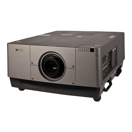
LCD PROJECTOR LC-XT6 MODEL Projection lens not included. ✽ Owner’s Manual Projector Operations ENGLISH TQBJ0489... -
Page 2: Read This First
Information Read this first! Read this first! WARNING: THIS APPARATUS MUST BE EARTHED. WARNING: To prevent damage which may result in fire or shock hazard, do not expose this appliance to rain or moisture. Machine Noise Information Ordinance 3. GSGV, January 18, 1991: The sound pressure level at the operator position is equal or less than 70 dB (A) according to ISO 7779. - Page 3 Read this first! IMPORTANT: THE MOULDED PLUG (U.K. only) FOR YOUR SAFETY, PLEASE READ THE FOLLOWING TEXT CAREFULLY. This appliance is supplied with a moulded three pin mains plug for your safety and convenience. A 13 amp fuse is fitted in this plug. Should the fuse need to be replaced, please ensure that the replacement fuse has a rating of 13 amps and that it is approved by ASTA or BSI to BS1362.
- Page 4 Model Number: LC-XT6 Trade Name: EIKI Responsible Party: EIKI International, Inc. Address: 30251 Esperanza Rancho Santa Margarita CA 92688-2132 Telephone number: 800-242-3454 (949)-457-0200 NOTIFICATION (Canada) This class A digital apparatus complies with Canadian ICES-003.
- Page 5 Read this first! WARNING: „ POWER The wall outlet or the circuit breaker shall be installed near the equipment and shall be easily accessible when problems occur. If the following problems occur, cut off the power supply immediately. Continued use of the projector in these conditions will result in fire or electric shock. z If foreign objects or water get inside the projector, cut off the power supply.
- Page 6 Do not touch other than the specified portion or remove the components. Doing so may impair the performance or safety. Use the ceiling mount bracket specified by EIKI. Using the ceiling mount bracket other than the specified one will result in falling accidents.
- Page 7 Read this first! WARNING: „ ACCESSORIES Do not use or handle the batteries improperly, and refer to the following. Failure to observe this will cause burns, batteries to leak, overheat, explode or catch fire. z Do not use unspecified batteries. z Use manganese or alkaline batteries but not rechargeable batteries.
- Page 8 Moving the projector with cables still attached can damage the cables, which will cause fire or electric shocks to occur. Use the lens specified by EIKI. Using the lens other than the specified one will result in malfunctions. z Before attaching the lens, check the projector model no. and optional lens model no. and use the lens suitable for the projector.
-
Page 9: Remote Control Battery
Read this first! To remove the battery Remote Control Battery 1. Press the guide and lift the cover. 2. Remove the batteries. (ii) Brazil Only Brasil Apenas „ Manuseio de baterias usadas BRASIL Após o uso, as pilhas e /ou baterias poderão ser entregues ao estabelecimento comercial ou rede de assistência técnica autorizada. - Page 10 Read this first! Trademarks •zHDMI, the HDMI logo and High-Definition Multimedia Interface are trademarks or registered trademarks of HDMI Licensing LLC. •zOther names, company names or product names used in these owner's manual are the trademarks or registered trademarks of their respective holders.
- Page 11 Features of the projector Features of the projector Quick steps Quick steps For details, see the corresponding pages. High clarity and high contrast image 1. Set up your projector. page 24) Image quality of high clarity with 16 000 lumens and high contrast with 2 500:1.
-
Page 12: Table Of Contents
Contents Contents Be sure to read “Read this first!”. ( pages 2 to 10) Power management function ........34 Important Information Projecting ............35 Read this first! ..........2 Selecting the input signal ...........35 Precautions for use ........14 Adjusting the image ............35 Using the remote control ...... - Page 13 Contents [Color temp.] ...............52 [Filter counter] .............72 White balance ([Red]/[Green]/[Blue]) ......52 [P-timer] ..............73 [Offset] .................52 [Test pattern] ...............74 [Auto picture control] ..........52 [Factory default] ............74 [Advanced color] ............52 [Information] menu ........75 [Sharpness] ..............53 Confirming the settings and usage state ....75 [Gamma] ..............53 [Network] menu ..........
-
Page 14: Precautions For Use
Precautions for use Precautions for use Cautions when transporting z When transporting the projector, hold it securely by its carry handle and avoid excessive vibration and impacts by such handling as dragging it on the floor. Failure to do so may damage the internal parts and result in malfunctions. -
Page 15: Security
Make your PIN code as difficult to guess as possible. z Change your PIN code periodically. z EIKI Industrial and its affiliate companies will never ask you directly for your PIN code. If you are asked directly, do not give your PIN code. -
Page 16: Optical Components
Precautions for use ■ Optical components If you are using the projecting a high-temperature environment or an environment which is dusty or full of cigarette smoke etc., the replacement cycle for optical components such as the the LCD panel and polarizer may reduce to as little as a year. -
Page 17: Accessories
PIN code label (N2QAYA000058) Wired remote control cable (K2KYYY00177) Cable tie AAA/R03/LR03 battery (for remote control unit) Power cord for LC-XT6 (E) (T0K3K0003--1) Power cord for LC-XT6 (U) (T0K3K0001--1) Power cord holder, power cord cover (T0STF0037--1) Computer cable (for D-sub) -
Page 18: Optional Accessories
Precautions for use ■ Contents of CD-ROM The following contents are stored on the supplied CD-ROM. Manual/Index (PDF) Software z Owner's Manual–Projector Operations z Real Color Manager Pro z Owner's Manual–Network Operations z PJ Network Manager z Owner's Manual–PJ Network Manager Operations z Real Color Manager Pro Software Operation Manual... -
Page 19: About Your Projector
About your projector About your projector Remote control (1) Remote control signal emitters (2) Remote control indicator Flashes by pressing any buttons. (3) <LIGHT> button Press once to light the control buttons for ten seconds. (18) (4) Power <ON> button Starts projection when the main power switch on the projector is set to and in the (19) -
Page 20: Projector Body
About your projector Attention z Do not drop the remote control. z Avoid contact with liquids or moisture. z Do not attempt to modify or disassemble the remote control. Note z The remote control can be used from any distance within about 5 m if pointed directly at the remote control sensor. -
Page 21: Control Panel
About your projector ■ Control panel (10) (11) (12) (1) Power <ON/STAND-BY> button (7) <AUTO PC ADJ.> button Turns off/on the power when the main power switch on the Automatically adjusts synchronization, total number of projector is set to dots, horizontal shift, and vertical shift. (2) <SHUTTER>... -
Page 22: Connection Terminals
About your projector ■ Connection terminals (10) (1) DVI-D input terminal <DIGITAL (DVI-D) IN> (6) Serial input terminal <SERIAL PORT IN> This terminal is for inputting the DVI-D signal. This input terminal is compatible with RS-232C and for externally controlling the projector by connecting the (2) HDMI input terminal <HDMI IN>... -
Page 23: Using The Remote Control
Using the remote control Using the remote control Inserting and removing the batteries 1) Open the cover. 2) Insert the batteries and close the cover. (ii) z Insert the side first. z To remove the batteries, follow the above procedure in reverse. Setting remote control numbers When you are using multiple projectors, you can set a remote control number to each projector to allow simultaneous control with a single remote control. -
Page 24: Setting Up
Setting up Setting up Attaching the lens Before putting the projector in position, attach the lens to the projector body. First, determine the correct lens for the environment in which you are going to use the projector. For lens product numbers and lens specifications suitable for the projector, consult your dealer. When attaching or replacing a lens, consult the technical staff or service personnel at a specialist dealer for safety. -
Page 25: Installation Options (Optional)
Setting up Installation options (optional) You can install the projector on the ceiling using the optional ceiling mount bracket. z Use only ceiling mount brackets specified for this projector. z For details on installation of the projector with the bracket, refer to the installation manual for the ceiling mount bracket. -
Page 26: Connections
Connections Connections Before connecting to the projector z Read carefully the instruction manual of the device you intend to connect. z Turn off the power switch of the device before connecting the cable. z If a connection cable is not supplied with the device and the optional cable is not available, prepare a connection cable to suit the device. -
Page 27: Connecting Example: Av Equipment
Connections Connecting example: AV equipment Video, S-video, DVD player, and HDMI video output devices S-video cable To <S-VIDEO IN> terminal To S-video output BNC cable To <Y,Pb/Cb,Pr/Cr IN> terminal To component video output BNC cable To composite To <VIDEO IN> terminal video output HDMI cable To HDMI output... -
Page 28: Tying Up The Cables Using Cable Ties
Connections Tying up the cables using cable ties Keep the cables tidy by fixing the cables connected to the terminals into the cable holders on the projector body. z The cable ties can be reused. (The tab can be loosened and released.) ■... -
Page 29: Installing An Input Module (Optional)
Installing an input module (optional) Installing an input module (optional) Installing an input module ■ Types of input module Purchase an input module (optional) matching the input signals of the system. Module name SD/HD-SDI input module Module number AH-72217 Input/output BNC 2 Input system, BNC 1 Output system terminal SMPTE259M-C standard:... -
Page 30: List Of Compatible Signals
Installing an input module (optional) ■ Using the input module Consult your dealer before using any of the optional input modules. When consulting your dealer, be sure to inform them of [Option control No.] of the projector. [Option control No.] is displayed in the [Information] menu. Language English Input... -
Page 31: Powering On/Off
Powering on/off Powering on/off Connecting the power cord ■ Installation ■ Removal 1) Insert the power cord holder in the 1) Push the power cord holder to the left. holes provided above and below the AC input terminal. z Push the power cord holder to the left to allow insertion of the power cord. -
Page 32: Power Indicator
Powering on/off Power indicator The power indicator informs you of the power status. Check the status of the power indicator <POWER> and the standby indicator <STAND-BY> before operating the projector. Power indicator <POWER> Standby indicator <STAND-BY> Indicator status Projector status Power indicator Standby indicator <POWER>... -
Page 33: Powering On The Projector
Powering on/off z When [Display] ( page 59) of the [Setting] menu is Powering on the projector set to [Off] or [Countdown off], projection will start as soon as the lamp comes on, regardless of [Logo select] ( page 65) setting. ... -
Page 34: Powering Off The Projector
Powering on/off Powering off the projector Direct power off function You can disconnect the power cord, turn off the power Control panel Remote control by the power breaker switch, etc. without pressing the power <STAND-BY> button on the remote control or the main power switch on the projector. -
Page 35: Projecting
Projecting Projecting Check the external device connections ( page 26) and power cord connections ( page 31) and then turn on the power ( page 33) to start projection. Select the input signal and adjust the image. Selecting the input signal Select an input signal. -
Page 36: Adjusting The Focus And Zoom
Projecting ■ Adjusting the focus and zoom 1) Press the <FOCUS> button and the <ZOOM> button on the remote control or the control panel. z [Focus] and [Zoom] are displayed on the screen for four seconds. 2) While the display appears, press ▲▼ to adjust the focus and zoom. Note z When [Display] is set to [Off], the adjustment screen will not appear. -
Page 37: Using The Remote Control
Using the remote control Using the remote control Using the freeze function You can temporarily freeze the projected image regardless of the state of playback in an external device. button 1) Press the <FREEZE> button on the remote control. z This freezes the image. 2) Press the button on the remote control or the control panel. -
Page 38: Correcting The Keystone Effect
Using the remote control ■ Corner correction Note z The signal displayed for the <INPUT 3> button and Corrects distortion at the corners of the image. the <INPUT 4> button changes depending on the 1) While [Keystone] is displayed, press type of input module inserted. -
Page 39: Adjusting Picture Quality
Using the remote control Adjusting picture quality Displaying a timer for presentations Pressing the <IMAGE ADJUST> button on the remote control displays the [Image adjust] menu. When you press the <P-TIMER> button on the remote control, the projector displays either a count of the time elapsed from the press of the button or a button countdown. -
Page 40: Menu Navigation
Menu navigation Menu navigation Navigating through menu Note z For certain formats of signal input to the projector, it will not be possible to adjust some items or use ■ Operating procedure some functions. The menu items that cannot be adjusted or used are grayed out, and cannot be 1) Press the <MENU>... -
Page 41: Main Menu
Menu navigation Main menu Sub menu The main menu contains the following eight items. The sub menu screen of the item selected from main When a main menu item is selected, the screen menu is displayed, and you can set and adjust the changes to a sub menu selection screen. - Page 42 Menu navigation ■ [Image adjust] ■ [Screen] Sub menu item Factory default Page Sub menu item Factory default Page [Contrast] [Normal] — [Brightness] [Full] — [Color]* [Wide(16:9)] — [Tint]* [Zoom] — [Color management] — [True]* — [Color temp.] [Mid] [Custom] —...
-
Page 43: Factory Default
Menu navigation ■ [Setting] ■ [Information] Details ( page 75) Sub menu item Factory default Page ■ [Network] [Language] [English] [Menu position] — Refer to “Owner's Manual–Network Operations”. Details ( page 76) [Display] [On] [Background] [Blue] [Lamp select] [4-Lamps] [Lamp power] (Auto) -
Page 44: [Input] Menu
[Input] menu [Input] menu [Input 2] Select [Input] from the main menu on the menu screen, and select the item from the sub menu. For operation of the menu screen, refer to 1) Press ▲▼ to select [Input 2], and “Navigating through menu”... -
Page 45: [System]
[Input] menu ■ For component input [System] The projector automatically selects [System] is displayed below the sub menu. [Auto] the scanning method of the input 1) Press ▲▼ to select [System] below signal. the sub menu and press the <SELECT> Component button. -
Page 46: [Pc Adjust] Menu
[PC adjust] menu [PC adjust] menu [Fine sync] Select [PC adjust] from the main menu on the menu screen, and select the item from the sub menu. Adjusts the projector when there is flicker due to a For operation of the menu screen, refer to tracking (synchronization) mismatch. -
Page 47: [Position V]
[PC adjust] menu [Position V] [Display area H] Adjusts the vertical position of the screen. Adjusts the horizontal resolution. 1) Press ▲▼ to select [Position V]. 1) Press ▲▼ to select [Display area H]. 2) Press the <SELECT> button. 2) Press the <SELECT> button. z The advanced menu is displayed. -
Page 48: [Reset]
[PC adjust] menu [Reset] The setting returns to its value before adjustment . 1) Press ▲▼ to select [Reset]. 2) Press the <SELECT> button. 3) Select [Yes], and press the <SELECT> button. z The setting returns to the value before adjustment. -
Page 49: [Image Select] Menu
[Image select] menu [Image select] menu Select [Image select] from the main menu on the menu screen, and select the item from the sub menu. For operation of the menu screen, refer to “Navigating through menu” ( page 40). z After selecting the item, press ▲▼◀▶... -
Page 50: [Image Adjust] Menu
[Image adjust] menu [Image adjust] menu [Color] Select [Image adjust] from the main menu on the menu screen, and select the item from the sub menu. This setting can only be adjusted for video or For operation of the menu screen, refer to component inputs. -
Page 51: [Color Management]
[Image adjust] menu ■ [COLOR MANAGEMENT LIST] [Color management] operations Adjusts the color of the projected image as desired. zRe-adjusting stored colors 1) Press ▲▼ to select [Color 1) Press ▲▼ to select the color to re- management]. adjust. 2) Press the <SELECT> button. 2) Press the <SELECT>... -
Page 52: [Color Temp.]
[Image adjust] menu [Color temp.] [Offset] 1) Press ▲▼ to select [Color temp.]. 1) Press ▲▼ to select [Offset]. 2) Press the <SELECT> button or ▶ . 2) Press the <SELECT> button. z The advanced menu is displayed. z The sub menu 2 is displayed. z While the advanced menu is displayed, press 3) Press ▲▼... -
Page 53: [Sharpness]
[Image adjust] menu [Sharpness] [Noise reduction] Reduces noise when viewing old video or other 1) Press ▲▼ to select [Sharpness]. images affected by noise. 2) Press the <SELECT> button. 1) Press ▲▼ to select [Noise reduction]. z The advanced menu is displayed. 2) Press the <SELECT>... -
Page 54: [Store]
[Image adjust] menu [Store] 1) Press ▲▼ to select [Store]. 2) Press the <SELECT> button or ▶ . z The registered content of each mode is displayed in the sub menu 2. 3) Press ▲▼ to select the mode to register. -
Page 55: [Screen] Menu
[Screen] menu [Screen] menu [Zoom] Select [Screen] from the main menu on the menu screen, and select the item from the sub menu. Stores the aspect ratio and projects at full panel size. For operation of the menu screen, refer to z When there is no input signal, this item is grayed “Navigating through menu”... -
Page 56: [Custom]
[Screen] menu [Custom] [Digital zoom +] The image is projected using the values registered as 1) Press ▲▼ to select [Digital zoom +]. [Store] in the [PC adjust] menu. z When there is no input signal, [Custom] can be 2) Press the <SELECT> button or ▶ . selected but the image will be projected in [Normal] z The menu screen is cleared and [Digital zoom +] mode. -
Page 57: [Digital Zoom -]
[Screen] menu [Digital zoom -] [Keystone] 1) Press ▲▼ to select [Digital zoom -]. 1) Press ▲▼ to select [Digital zoom -]. 2) Press the <SELECT> button or ▶ . 2) Press the <SELECT> button or ▶ . z The menu screen is cleared and [Digital zoom -] z The adjustment screen of the sub menu 2 is is displayed. -
Page 58: [Ceiling]
[Screen] menu ■ [Corner pattern] [Rear] Selects the corner pattern mode displayed during Sets the projection method in accordance with the corner correction. installation status of the projector. 1) Select [Corner pattern], and press the If the screen display has flipped, select [On]. <SELECT>... -
Page 59: [Setting] Menu
[Setting] menu [Setting] menu [Display] Select [Setting] from the main menu on the menu screen, and select the item from the sub menu. Sets the display of the on-screen menu. For operation of the menu screen, refer to 1) Press ▲▼ to select [Display]. “Navigating through menu”... -
Page 60: [Background]
[Setting] menu [Background] Note z If a lamp fails as a result of a fault or reaching the end of its service life, the lamp indicator <LAMP Selects the background screen when there is no input REPLACE> on the front of the projector body and signal. -
Page 61: [Lamp Interval]
[Setting] menu ■ To adjust the blending start [Lamp interval] position and blending width Sets the replacement cycle when [Lamp select] is set 1) Press ▲▼ to select the location to [2-Lamps]. After the replacement cycle, the lamp for use is automatically changed. ([Start]/[Width] of [Left]/[Right]/[Top]/ z The set time here is a guideline time. -
Page 62: [Color Matching]
[Setting] menu ■ To display the test pattern [Color matching] 1) Press ▲▼ to select [Test pattern]. Makes it less easy to see different projector coloring when multiple screens are used. 2) Press the <SELECT> button. 1) Press ▲▼ to select [Color matching]. 3) Press ▲▼... -
Page 63: [Advanced Color Matching]
[Setting] menu ■ To display the test pattern [Advanced color matching] 1) Press ▲▼ to select [Auto test pattern]. More advanced settings than [Color matching] are possible. 2) Press the <SELECT> button. 1) Press ▲▼ to select [Color matching]. 3) Press ▲▼ to switch the setting. 2) Press the <SELECT>... - Page 64 [Setting] menu ■ To check [Measured] ■ To display the test pattern Displays data for R/G/B. 1) Press ▲▼ to select [Auto test pattern]. 1) Press ▲▼ to select the color ([Red]/ 2) Press the <SELECT> button. [Green]/[Blue] in [Measured]) to be 3) Press ▲▼...
-
Page 65: [Hdmi Setup]
[Setting] menu ■ To register adjusted content you [HDMI setup] have changed If the image cannot be correctly displayed when an Registers values after adjustment. external device is connected to the projector using 1) Press ▲▼ to select [Store]. HDMI, change the settings. 1) Press ▲▼... - Page 66 [Setting] menu ■ [Capture] Note z The entered PIN code is displayed with * mark on This function enables you to capture an image the screen. being projected to use it for a starting-up display z The factory default setting for the logo PIN code is or background screen.
-
Page 67: [Fan Control]
[Setting] menu [Fan control] [RC sensor] The projector controls the rotation of the fan Enables and disables the remote control sensor on automatically. You can make the rotation of the fan the projector body. stronger depending on the ambient temperature or 1) Press ▲▼... -
Page 68: [Power Management]
[Setting] menu [Power management] [Direct on] This is a function for automatically switching on 1) Press ▲▼ to select [Power the power of the projector when the power cord is management]. connected, without requiring operations on the power <ON> button on the remote control or the power <ON/ 2) Press the <SELECT>... -
Page 69: [Security]
[Setting] menu ■ [PIN code lock] [Security] Sets the PIN code to restrict projector operations Locks projector operations using button locking and to the administrator. the PIN code. 1) Select [PIN code lock], and press the 1) Press ▲▼ to select [Security]. <SELECT>... -
Page 70: [Projector Id]
[Setting] menu ■ [PIN code change] [Shutter] Changes the logo PIN code. Sets the shutter function. 1) Select [PIN code change], and press 1) Press ▲▼ to select [Shutter]. the <SELECT> button. z The PIN code input screen is displayed. 2) Press the <SELECT>... -
Page 71: [Video Delay Control]
[Setting] menu ■ [Effect] Note z When the management function is active, the lamp Sets special effects when shutter is opened and is turned off and the projector will begin a cooling closed. operation. 1) Select [Effect], and press the z When cooling has finished, the power of the <SELECT>... -
Page 72: [Closed Caption]
[Setting] menu ■ [Filter type] [Closed caption] Selects the type of filter to be used. Sets the color of the closed captions and selections. 1) Select [Filter type], and press the 1) Press ▲▼ to select [Closed caption]. <SELECT> button. z ▲▼... -
Page 73: [P-Timer]
[Setting] menu ■ [Filter counter reset] ■ [Start] Resets the value of [Filter counter]. Starts the count-up or countdown. After replacing the filter, be sure to reset the 1) Select [Start], and press the <SELECT> counter. button. 1) Select [Filter counter reset], and press z The menu screen is cleared and the timer is the <SELECT>... -
Page 74: [Test Pattern]
[Setting] menu [Test pattern] [Factory default] Returns settings other than the following to the factory 1) Press ▲▼ to select [Test pattern]. default settings. 2) Press the <SELECT> button. [Logo PIN code lock] z The sub menu 2 is displayed. [PIN code lock] 3) Press ▲▼... -
Page 75: [Information] Menu
[Information] menu [Information] menu ■ [Lamp 3] Select [Information] from the main menu on the menu screen. Displays the usage time and status of the lamp 3. For operation of the menu screen, refer to ■ [Lamp 4] “Navigating through menu” ( page 40). -
Page 76: [Network] Menu
[Network] menu [Network] menu Select [Network] from the main menu on the menu screen, and select the item from the sub menu. For operation of the menu screen, refer to “Navigating through menu” ( page 40). z After selecting the item, press ◀▶▲▼ to make the setting. -
Page 77: About Indicator Status
About indicator status About indicator status If an indicator turns on If a problem occurs within the projector, it will be notified with the temperature indicator <WARNING TEMP.>, the filter indicator <WARNING FILTER>, the shutter indicator <SHUTTER>, and the lamp indicator <LAMP REPLACE>. - Page 78 About indicator status ■ When operating correctly The status of the indicator is displayed with the following symbols. s: Off, l: On, H: Flashing, ■: On or Flashing Indicator <STAND- <WARNING <WARNING <LAMP Status of the projector <POWER> <SHUTTER> BY> TEMP.>...
- Page 79 About indicator status ■ When there is a problem with internal temperature The status of the indicator is displayed with the following symbols. s: Off, l: On, H: Flashing, ■: On or Flashing Indicator <STAND- <WARNING <WARNING <LAMP Status of the projector <POWER>...
- Page 80 About indicator status ■ When there is a problem with internal power The status of the indicator is displayed with the following symbols. s: Off, l: On, H: Flashing, ■: On or Flashing Indicator <STAND- <WARNING <WARNING <LAMP Status of the projector <POWER>...
- Page 81 About indicator status ■ When there is a problem with the lamp The status of the indicator is displayed with the following symbols. s: Off, l: On, H: Flashing, ■: On or Flashing Indicator <STAND- <WARNING <WARNING <LAMP Status of the projector <POWER>...
- Page 82 About indicator status ■ When there is a problem with the shutter The status of the indicator is displayed with the following symbols. s: Off, l: On, H: Flashing, ■: On or Flashing Indicator <STAND- <WARNING <WARNING <LAMP Status of the projector <POWER>...
-
Page 83: Maintenance/Replacement
Maintenance/replacement Maintenance/replacement Before maintaining/replacing the unit z When maintaining or replacing the unit, always turn off the power and remove the power plug from the outlet. pages 31, 34) z When turning off the power, make sure to follow the procedures in “Powering off the projector” ( page 34). - Page 84 Maintenance/replacement 2) Remove the holder. z Loosen the three screws on the holder (A, B), slide the holder in the direction shown by the arrow in the image, and lift up to remove the holder. Holder B Screw Holder A 3) Remove the air filter.
-
Page 85: Lamp Unit
Maintenance/replacement ■ Lamp unit The lamp unit is a consumable component. Check the lamp usage duration with “[Information] menu” page 75) and perform regular replacement. If the replacement message is displayed on the screen and the lamp indicators <LAMP 1 REPLACE> to <LAMP 4 REPLACE>... -
Page 86: Replacing The Lamp Unit
Maintenance/replacement ■ Replacing the lamp unit Attention z Turn off the UV lamp before opening the lamp cover. z When the projector is mounted on the ceiling, do not put your face near the lamp unit. z Attach the lamp unit securely. z If the lamp unit is not attached properly, remove it and then attach it again. - Page 87 Maintenance/replacement 4) Use a Phillips screwdriver to turn the lamp unit fixing screws (two screws) until they turn freely, and then holding the handle, slowly pull out the lamp unit from the projector. Lamp unit Screw 5) Insert the new lamp unit taking note of its direction, and use a Phillips screwdriver to firmly tighten the lamp unit fixing screws (two screws).
-
Page 88: Troubleshooting
Troubleshooting Troubleshooting Review the following points. For details, see the corresponding pages. Problem Points to be checked page z Is the power plug firmly inserted into the outlet? — z Is the main power switch turned to z Is the power supplied from the outlet? —... - Page 89 Troubleshooting Problem Points to be checked page The control buttons z Is the projector operation locked with [Key lock] in the [Setting] menu? of the projector do not work. z Is [Input] selected correctly? z Is [Image adjust] adjusted correctly? z Is [Screen] selected correctly? The correct picture is not displayed.
-
Page 90: Technical Information
Technical Information Technical Information Adjusting screens of multiple screen images [Edge blending] and [Color matching] allow images from multiple projectors to be overlapped seamlessly. ■ [Edge blending] 1) Check that the settings of [Screen] and [Image adjust] of each projector are the same. -
Page 91: Color Matching
Technical Information 6) Then use [Lens shift] to overlap the shaded areas. z The red line will turn yellow if it is overlapped correctly. Edge blending Edge blending Left Start Left Start Width Width Right Start Right Start Width Width Start Start Width... - Page 92 Technical Information zAdjusting colors with a colorimeter 1) Turn [Advanced color matching] to [On]. 2) Select [Test pattern] and press the <SELECT> button. z Displays the test pattern selection screen. 3) Select [Red] (or [Green], [Blue]) from [Measured] and press the <SELECT> button. z The test pattern is displayed.
-
Page 93: Label Notifying Registration Of Password
Technical Information Label notifying registration of password Apply the supplied label to the projector in a visible location when the password is registered and valid. PJLink This projector complies with Class1 as defined by JBMIA (Japan Business Machine and Information System Industries Association) PJLink standards. -
Page 94: Serial Terminal
Technical Information ■ PJLink The PJLink subcommittee was established within the Data Projector Group in September 2003. The new PJLink interface specification for projectors was stipulated by the PJLink subcommittee as part of its first year of activities. PJLink is a unified standard for the control and management of projectors. The standard allows centralized management of projectors and operation with a controller, regardless of manufacturer. -
Page 95: Serial Control Interface
Technical Information Serial Control Interface This projector provides a function to control and monitor the projector's operations by using the RS-232C serial port. ■ Operation 1) Connect a RS-232C serial cross cable to <SERIAL PORT IN> on the projector and serial port on the PC ( page 26). -
Page 96: Status Read Commands
Technical Information ■ Status Read Commands Format The command is sent from PC to the projector with the format below; “CR” [Command] [CR] Command: one character (refer to the command table below.) The projector decodes the command and returns the 'Character string' with the format below; Return Command Function... -
Page 97: Other Terminals
Technical Information Other terminals ■ <S-VIDEO IN> terminal pin assignments and signal names Pin No. Signal name Outside view GND (luminance signal) GND (color signal) Luminance signal Color signal ■ <ANALOG IN> terminal pin assignments and signal names Pin No. Signal name Outside view +5 V... - Page 98 Technical Information ■ <DIGITAL (DVI-D) IN> terminal pin assignments and signal names Pin No. Signal name Pin No. Signal name Outside view T.M.D.S data 2 - (13) – T.M.D.S data 2 + (14) +5 V T.M.D.S data 2/4 (15) shield –...
-
Page 99: List Of Compatible Signals
Technical Information List of compatible signals The following table specifies the types of signal compatible with the projector. ■ When the signal is analog Screen display Resolution Scanning frequency Dot clock mode (dots) Horizontal (kHz) Vertical (Hz) frequency (MHz) VGA 1 640 x 480 31.470 59.880... - Page 100 Technical Information Screen display Resolution Scanning frequency Dot clock mode (dots) Horizontal (kHz) Vertical (Hz) frequency (MHz) SXGA 17 1 152 x 900 61.850 66.000 94.500 SXGA 18 1 280 x 1 024i 46.430 86.700 78.745 SXGA 19 1 280 x 1 024 63.790 60.180 108.190...
- Page 101 Technical Information ■ When the signal is digital Screen display Resolution Scanning frequency Dot clock mode (dots) Horizontal (kHz) Vertical (Hz) frequency (MHz) D-VGA 640 x 480 31.470 59.940 25.175 D-480i 720 (1 440) x 480 15.734 59.940 27.000 D-576i 720 (1 440) x 576 15.625 50.000...
-
Page 102: Specifications
Specifications Specifications The following table describes the specifications of the projector. Model No. LC-XT6 Power supply AC 200 V - 240 V 50 Hz/60 Hz 200 V - 240 V 11 A 1 850 W Power consumption When [Lamp power] in the [Setting] menu is set to eco-mode: 1 450 W... - Page 103 Specifications Model No. LC-XT6 Power cable length 3.0 m (118-1/8") Outer case Molded plastic Width: 650 mm (25-5/8") Height: 349 mm (13-3/4") (feet fully retracted) Dimensions Depth: 815 mm (32-1/8") (feet fully retracted, not including lens) Weight Approx. 46.5 kg (102.5 lbs.) Operating environment temperature : 5°C (41°F) to 40°C (104°F)
-
Page 104: Dimensions
Dimensions Dimensions <Unit: mm> 144.0 (5-21/32") 143.0 (5-5/8") 25.0 (31/32") 82.0 (3-7/32") 815.0 (32-3/32") 224.0 (8-13/16") * Actual dimension may differ depending on the product. 104 - ENGLISH... -
Page 105: Ceiling Mount Bracket Safeguards
Installation work of the ceiling mount bracket should only be performed by a qualified technician. z EIKI takes no responsibility for any damage to the projector resulting from use of a ceiling mount bracket not manufactured by EIKI or the inappropriate choice of location for installation, even if the warranty period of the projector has not expired. -
Page 106: Notes On Attaching The Lens
Notes on attaching the lens Notes on attaching the lens The technical staff or service personnel must attach the lens according to the instruction manual supplied with the optional lens. z Use the light-shielding plates, lens attachment, spacer, and lens lock lever fixing bracket supplied with the projector when attaching the lens. - Page 107 Notes on attaching the lens ■ Light-shielding plate for each lens Three types of light-shielding plates are supplied with the projector. Use the light-shielding plate that corresponds to the appropriate lens. Refer to the following table. Accessory (product name) Lens Product No. Attention Light-shielding plate-1 AH-32022...
- Page 108 Notes on attaching the lens Information for Users on Collection and Disposal of Old Equipment and used Batteries These symbols on the products, packaging, and/or accompanying documents mean that used electrical and electronic products and batteries should not be mixed with general household waste.
- Page 109 U.S.A. Canada EIKI International, Inc. EIKI CANADA - Eiki International, Inc. 30251 Esperanza P.O. Box 156, 310 First St. - Unit 2, Rancho Santa Margarita Midland, ON, L4R 4K8, Canada CA 92688-2132 Tel : 800-563-3454 (705)-527-4084 U.S.A. Fax : 800-567-4069 (705)-527-4087...
Need help?
Do you have a question about the LC-XT6 and is the answer not in the manual?
Questions and answers