Table of Contents
Advertisement
Quick Links
VIDEO CASSETTE RECORDER
SR-L911US
REC
STOP/EJECT
REC
CHECK
PAUSE/
REVERSE
STILL
PLAY
MENU
FIELD
REW
FF
TIME
ADVANCE
MODE
24H
Before operating this unit, please read
the instructions carefully to ensure the
best possible performance.
R
HIGH DENSITY
VIDEO CASSETTE RECORDER
SHIFT/TRACKING
SET/V.LOCK
INSTRUCTIONS
SR-L911US
SHUTTLE
FIELD
FIELD
ADVANCE
REV
SHUTTLE
/FIELD
COUNT/
AL/PL
CLOCK
RESET
OPE. LOCK
OPERATE
RESET
TIMER
/CANCEL
REC
ON
SKIP/ALARM
SEARCH
For Customer Use:
Enter below the Serial No. which is
located on the rear of cabinet. Retain
this information for future reference.
Model No.
Serial No.
FWD
SR-L911US
SL96199H
Advertisement
Table of Contents

Related Manuals for JVC SR-L911US


Summary of Contents for JVC SR-L911US
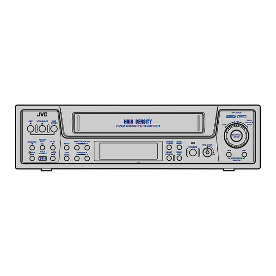
- Page 1 VIDEO CASSETTE RECORDER SR-L911US INSTRUCTIONS SR-L911US SHUTTLE FIELD HIGH DENSITY FIELD STOP/EJECT ADVANCE CHECK VIDEO CASSETTE RECORDER SHUTTLE /FIELD PAUSE/ REVERSE STILL PLAY SHIFT/TRACKING COUNT/ AL/PL CLOCK RESET MENU OPE. LOCK OPERATE FIELD RESET TIME SET/V.LOCK TIMER ADVANCE /CANCEL MODE...
- Page 2 This equipment generates, uses, and can radiate radio WARNING: frequency energy and, if not installed and used in accordance The battery used in the SR-L911US must be replaced at with the instructions, may cause harmful interference to radio the JVC authorized service dealer only.
-
Page 3: Table Of Contents
11-1 Rear Panel's Input/Output ......53 11-2 Specifications ..........54 JVC is not liable for compensation for loss or damage to recordings in the event this unit fails to record or play back properly because the unit malfunctions or a defective video cassette tape is used. -
Page 4: Introduction
As replacement and adjustment of parts require advanced skills and specialized equipment, please contact the person in charge of professional video equipment at your nearest JVC-authorized service agent for servicing. Monitoring Usage Time... -
Page 5: Precautions
Check the quality of the image shown on the monitor. Check that the date and time shown on the monitor are If any problems are found after inspection, turn the power off, unplug the power plug from the AC outlet, and contact your correct. JVC dealer. -
Page 6: Controls And Connectors
2 CONTROLS AND CONNECTORS 2-1 Front Panel SR-L911US SHUTTLE FIELD HIGH DENSITY FIELD STOP/EJECT ADVANCE CHECK VIDEO CASSETTE RECORDER SHUTTLE /FIELD PAUSE/ REVERSE STILL PLAY SHIFT/TRACKING COUNT/ AL/PL CLOCK RESET MENU OPE. LOCK OPERATE FIELD SET/V.LOCK RESET TIMER TIME ADVANCE... - Page 7 2 CONTROLS AND CONNECTORS 2-1 Front Panel & [STOP/EJECT] button [COUNT/CLOCK] button • Stops the tape. Press this button to select the time display or tape • Ejects the tape when pressed in the Stop mode. counter in the display. When the power is turned off, the time is displayed.
-
Page 8: Display
2-2 Display 12 13 Operation mode display Recording/playback mode time display Shows the operation modes. • Shows the recording/playback mode set with the [TIME MODE] button. • When a tape ends in the Record mode, the record time mode indication goes out and the "End" indication Fast- Timelapse blinks (when the <REC REMAIN>... -
Page 9: Rear Panel
[CLOCK IN] terminal of another connector even when no power is supplied to the unit SR-L911US, this unit’s time can be synchronized with (Power-Off Video Throughput function). the time on the other VCR if the time difference is within ±30 seconds. - Page 10 2 CONTROLS AND CONNECTORS VIDEO AUDIO CAM SW ALARM ALARM SERIES/CLOCK REC OUT WARNING REMOTE ALARM TAPE /REC RESET END OUT CAM SW ALARM ALARM SERIES/CLOCK REC OUT WARNING & ALARM TAPE /REC RESET END OUT Connecting the wires to the terminals 1.
-
Page 11: Connections
Monitor TV Connect the monitor’s video/audio input connectors to the SR-L911US’s video/audio output connectors. Connect the video camera’s video output connector to the SR-L911US’s video input connector. Input audio signals to the audio input connectors via an amplifier. When connecting an alarm sensor, connect it to the SR-L911US’s alarm input terminal. -
Page 12: Connecting A System Using A Sequential Switcher
Connect the sequential switcher’s (frame switcher) alarm signal output, camera switching signal input and video output to the SR-L911US. Connect the monitor’s video/audio input connectors to the SR-L911US’s video/audio output connectors. When the connection is complete, connect the power plug to an AC 120 V, 50 Hz/60 Hz outlet. -
Page 13: Connecting The Rear Panel Input/Output Terminal Connections
3 CONNECTIONS 3-3 Connecting the Rear Panel Input/Output Terminal Connections [CAM SW OUT] camera switching signal output terminal [ALARM IN] alarm signal input terminal CAM SW ALARM Sequential switcher Sequential switcher camera switching alarm output signal input terminal [ALARM RESET] alarm reset terminal [ALARM REC OUT] alarm recording mode signal output terminal ALARM ALARM... -
Page 14: Monitor On-Screen Display
4 MONITOR ON SCREEN DISPLAY Status information and other data including date/time, alarm input data, power loss (power failure) data and total operation hours can be displayed on a connected monitor. Function settings can be switched via the on-screen function menu switches and menu screens are also provided for timer recording program setting and date/time setting. -
Page 15: Main Menu Display
4 MONITOR ON-SCREEN DISPLAY 4-2 Main Menu Display You can display date and time data recorded when an alarm input or power failure occurs, as well as the hour meter (drum rotating time) by selecting the desired item in the main menu. The timer recording program setting screen, function menu switch setting screen, and date/time setting screen can also be displayed by selecting the desired item in the main menu. -
Page 16: Alarm Input/Power Loss Data Display
4 MONITOR ON-SCREEN DISPLAY [SHIFT +/–] buttons [MENU] button SR-L911US SHUTTLE FIELD HIGH DENSITY FIELD STOP/EJECT ADVANCE CHECK VIDEO CASSETTE RECORDER SHUTTLE /FIELD PAUSE/ STILL PLAY SHIFT/TRACKING COUNT/ AL/PL REVERSE CLOCK RESET MENU OPE. LOCK OPERATE FIELD SET/V.LOCK RESET TIMER... -
Page 17: Setting Of The Function Menu Switches
5 SETTING OF THE FUNCTION MENU SWITCHES You can customize the VCR's functions to suit the requirements of your application using on-screen menu's function switches. [SHIFT –] button [SHIFT +] button [MENU] button SR-L911US SHUTTLE FIELD HIGH DENSITY FIELD STOP/EJECT... -
Page 18: Contents Of The Function Menu Switches
5-2 Contents of the Function Menu Switches Three function menu switch setting screens are available. ]: Factory setting Screens Items Set values Function On-screen POSITION [L-UP] Sets the on-screen position of time/date and recording mode data. If no on- mode setting R-UP screen display is required, use this menu switch to turn it off. - Page 19 5 SETTING OF THE FUNCTION MENU SWITCHES 5-2 Contents of the Function Menu Switches ]: Factory setting Screens Items Set values Function VTR mode 1 INDEX [OFF] Enables or disables the Index Search function. OFF : The index search function is disabled. setting SEARCH ON : The index search function is enabled with the [SKIP/ALARM SEARCH]...
- Page 20 5 SETTING OF THE FUNCTION MENU SWITCHES 5-2 Contents of the Function Menu Switches ]: Factory setting Screens Items Set values Function Alarm/sensor ALARM REC [OFF] Turns the alarm recording function on or off. recording mode Alarm recording is enabled only in the Timelapse Record mode. setting An index code (VISS signal) is also recorded at the start point of alarm recording as an alarm cue signal.
-
Page 21: Preparation
6 PREPARATION 6-1 Cassette Loading/Unloading Loading Insert the cassette with its label side facing you. Gently push the center of the cassette until the machine starts automatic loading. [EJECT] button SR-L911US SHUTTLE FIELD HIGH DENSITY FIELD STOP/EJECT ADVANCE CHECK VIDEO CASSETTE RECORDER... - Page 22 • The first time you turn on the power, the time display shows a blinking "0:00:00". • When the built-in backup battery capacity is low, the error indication E-10 appears on the display. Contact your local JVC dealer to replace the built-in battery.
-
Page 23: Summer Time Compensation
• The time advances one hour on the display At the end of the daylight savings time season, set the <SUMMER TIME> switch to OFF. • The standard time instead of "Summer Time" is displayed. 6-4 Selection of Record/Play Mode SR-L911US SHUTTLE FIELD HIGH DENSITY FIELD STOP/EJECT... -
Page 24: Preparation
7 RECORDING 7-1 Preparation [MENU] button SR-L911US SHUTTLE FIELD FIELD HIGH DENSITY STOP/EJECT ADVANCE CHECK VIDEO CASSETTE RECORDER SHUTTLE /FIELD PAUSE/ REVERSE STILL PLAY SHIFT/TRACKING COUNT/ AL/PL CLOCK RESET MENU OPE. LOCK OPERATE FIELD RESET TIME SET/V.LOCK TIMER ADVANCE /CANCEL... -
Page 25: Recording
7 RECORDING 7-2 Recording [STOP/EJECT] button [REC CHECK] button [REC] button SR-L911US SHUTTLE FIELD HIGH DENSITY FIELD STOP/EJECT ADVANCE CHECK VIDEO CASSETTE RECORDER SHUTTLE /FIELD PAUSE/ REVERSE STILL PLAY SHIFT/TRACKING COUNT/ AL/PL MENU CLOCK RESET OPE. LOCK OPERATE FIELD TIME SET/V.LOCK... -
Page 26: Timer Recording
• Weekly timer : Set the day of the week. Recording will automatically be performed on that day each week. You can program the timer using the on-screen menu display. [SHIFT–] button [MENU] button [SHIFT+] button SR-L911US SHUTTLE FIELD HIGH DENSITY FIELD... - Page 27 7 RECORDING 7-3 Timer Recording Select the timer program No. Start time (minute) Press the [SHIFT +] or [SHIFT -] button to move the Stop time (hour) Start time (hour) cursor arrow to the program No. to be set. Stop time (minute) •...
- Page 28 7-3 Timer Recording Setting the weekly timer Daily timer program setting screen PROGRAM TIMER You can program the VCR to record on a specified day ( DAILY) S T A R T E N D MODE each week. 1. – – – – – – – : – – – – : – – – – H 2.
- Page 29 7 RECORDING 7-3 Timer Recording Setting dates when timer recording is not [MENU] button executed (cancel program) [SHIFT–] button [SHIFT+] button Up to 16 days of timer-recorded programming within a year can be canceled. This function is useful for irregular days such as holidays, national holidays or special days.
- Page 30 7-3 Timer Recording Changing a preset timer program If program data overlaps The Timer Record Standby mode is engaged and the OVER LAP indication blinks for about 10 seconds. Press the [TIMER REC] button to turn off the TIMER The OVER LAP indication is not shown, however, if the indication in the display.
-
Page 31: Alarm Recording
VCR automatically switches to the 8H (EP) mode for realtime recording of the alarm situation. Normal timelapse recording is restored after the preset alarm recording duration has passed. * Alarm recording will not start from the Pause mode. SR-L911US SHUTTLE FIELD... - Page 32 7-4 Alarm Recording Preparation Connect an alarm sensor to the rear panel’s alarm input terminal. Press the [OPERATE] button to turn the operating mode A LARM / SENSOR REC MODE Alarm recording function Setting the function menu switches for the Alarm (ALARM REC) Record mode (SENSOR REC)
-
Page 33: Sensor Recording
Perform the settings for sensor recording in the same way as for "Alarm Recording" on page 31. The mechanism of the SR-L911US cannot be guaranteed if the sensor recording function is used frequently (100 times/ day or more). If alarm inputs are frequent, use the alarm recording function instead and carry out regular maintenance/ inspection and parts replacement. -
Page 34: Repeat Recording
7-6 Repeat Recording When the tape reaches the end during recording, it is automatically rewound and recording starts again from the beginning. 5 To execute repeat recording, set <TAPE END MODE> on the VTR mode 1 setting screen to REPEAT. VTR MODE 1 Auto recording (SHARPNESS) -
Page 35: Series Recording
7 RECORDING 7-7 Series Recording The series recording function facilitates recording over much longer periods using several connected SR-L911USs. As soon as the tape ends in one VCR, the next VCR in the series starts recording. Connections 5 Connect the first VCR’s [SERIES/CLOCK OUT] terminal Rear panel to the second VCR’s [SERIES/CLOCK IN] terminal. -
Page 36: Recording With External Vcr Activation Signal
To [SERIES/CLOCK IN] terminal External control equipment Connection Connect the [SERIES/CLOCK IN] terminal and [COM] VCR control signal (ground signal) terminal on the SR-L911US’s rear panel to the external control equipment. LV: 0 V Start of recording Stop or power off Operation Set the function menu switch <TERMINAL SEL 1>... -
Page 37: How To Restore Recording After Power Failure
VTR mode 1 setting screen 7-10 External Timer Recording External timer recording can be performed by connecting the SR-L911US to an external timer. Check that a cassette is loaded in the VCR. Set the function menu switch <AUTO REC> to ON. -
Page 38: Playback And Special-Effects Playback
8 PLAYBACK AND SPECIAL EFFECTS PLAYBACK [STOP/EJECT] button SR-L911US SHUTTLE FIELD HIGH DENSITY FIELD STOP/EJECT ADVANCE CHECK VIDEO CASSETTE RECORDER SHUTTLE /FIELD PAUSE/ REVERSE STILL PLAY SHIFT/TRACKING COUNT/ AL/PL CLOCK RESET MENU OPE. LOCK OPERATE FIELD TIME SET/V.LOCK RESET TIMER... -
Page 39: Special-Effects Playback
8 PLAYBACK AND SPECIAL-EFFECTS PLAYBACK [REVERSE] button [PLAY] button SR-L911US SHUTTLE FIELD HIGH DENSITY FIELD STOP/EJECT ADVANCE CHECK VIDEO CASSETTE RECORDER SHUTTLE /FIELD PAUSE/ REVERSE STILL PLAY SHIFT/TRACKING COUNT/ AL/PL CLOCK RESET MENU OPE. LOCK OPERATE FIELD RESET TIME SET/V.LOCK... -
Page 40: Special-Effects Playback (Shuttle Ring Operation)
[SHUTTLE/FIELD] buttons SR-L911US FIELD SHUTTLE HIGH DENSITY FIELD STOP/EJECT ADVANCE CHECK VIDEO CASSETTE RECORDER SHUTTLE /FIELD PAUSE/ REVERSE STILL PLAY SHIFT/TRACKING COUNT/ AL/PL MENU CLOCK RESET OPE. LOCK OPERATE FIELD SET/V.LOCK RESET TIMER TIME ADVANCE /CANCEL MODE SKIP/ALARM SEARCH [REVERSE] button... -
Page 41: Index Search
Index signal (VISS) recorded every one hour SEARCH * The number of indexes is shown in the display [SKIP/ALARM SEARCH] and counted down as search progresses. button 8-6 Tracking/V. Lock Adjustment [TRACKING +/-] button SR-L911US SHUTTLE FIELD FIELD HIGH DENSITY STOP/EJECT ADVANCE CHECK... -
Page 42: Troubleshooting
When the error indication E- – – is shown, turning the Buzzer sound (WARNING BUZZER) operating mode on again may not clear the problem. PRESS (SHIFT, SET) In this case, consult your local JVC dealer (for E-01 to PRESS (MENU) E-07). VTR mode 1 setting screen Error... -
Page 43: No Error Indication
Dust may have accumulated on the Clean the video heads. Consult your back, the picture becomes rough video heads. nearest JVC dealer. or disappears. During playback, sound is high- Are you playing back a tape recorded Play back the tape in the same mode pitched and hard to hear. -
Page 44: Optional Sa-K97U Rs-232C Interface Board
SA-K97U RS-232C interface board is installed. Operation status can also be monitored on the computer. 10-1. Installation of the SA-K97U Rear panel The procedure is shown below. However, to avoid electric shock or injury, contact your local JVC service center for details. VIDEO AUDIO... -
Page 45: Sa-K97U Specifications
10. OPTIONAL SA-K97U RS-232C INTERFACE BOARD 10-2. SA-K97U Specifications 9-pin connector specifications Pin NO. Signals Operations Direction of signals Receive data VTR p CPU Transmit data VTR [ CPU Data terminal ready VTR [ CPU Signal ground Data set ready VTR p CPU Output level ON : +5 V or more... -
Page 46: Sa-K97U Rs-232C Protocol & Commands
10-3. SA-K97U RS-232C Protocol & Commands RS-232C protocol JVC base table Data “0” ENTER COMPLE- Data “1” CLEAR TION ERROR ERROR Data “2” COUNT RESET CASSETTE Data “3” EJECT Data “4” Data “5” TARGET Data “6” CLEAR TABLE1 ON Data “7”... - Page 47 Transmit the command “JVC TABLE 1 ON” (F6H) to the VCR. The VCR will return “ACK” (0AH). The VCR can now receive any command described in this section. To cancel the communications mode, transmit the command “JVC TABLE 1 OFF” (F7H).
- Page 48 After transmitting the VISS SEARCH command (17), transmit the appropriate 2-byte numeric data (from 30H to 39H), the data input command (40H), and either FF (ABH) or REW (ACH). All commands should be transmitted separately one byte at a time with “ACK” (0AH) confirmation from the VCR after each transmission.
- Page 49 10. OPTIONAL SA-K97U RS-232C INTERFACE BOARD 5 Date and time setting commands DATE SET (8EH) : Set the current date (month, day, year) for the VCR. After this command (8EH) is sent, input 1- byte numerical data (30H — 39H). (Example) Sep., 30, 2000 Time Month...
- Page 50 2-3 Commands for VCR status verification DATE SENSE (BEH) : The VCR returns the currently set month, day and year as 6 bytes. Each byte has a value of 30H to 39H. 30H corresponds to 0 and 39H to 9. (Example: For Sep., 14, 2000, the VCR returns 30H, 39H, 31H, 34H, 30H and 30H.) TIME SENSE (BFH) : The VCR returns the currently set hour, minute and second as 6 bytes.
- Page 51 In this case, release the warning via the RS-232C with the CLEAR (56H). To release it on the VCR, turn the [OPERATE] button off and on again. (10) ALARM INPUT (06H) : SR-L911US return code This is returned when an alarm signal is input during recording.
- Page 52 10. OPTIONAL SA-K97U RS-232C INTERFACE BOARD 2-4 Others (Input data correction/Error cancellation) These are return codes from the SR-L911US. (Error-related codes only) ERROR (02H) : This is returned when commands of more than 1 byte are transmitted to the VCR and an illegal command is received in the 2nd byte (or later) of the transmitted command.
-
Page 53: Appendixes
11 APPENDIXES 11-1 Rear Panel’s Input/Output [CAM SW OUT] camera switching signal output The CAM SW OUT terminal outputs a camera switching timing signal to the connected sequential switcher. The switching interval can be set with the <CAMERA SW> on the VTR mode 1 setting screen. The camera switching signal is output at ground level. Camera switching During recording... -
Page 54: Specifications
5 Signal output 1.0 Vp-p, 75 ohms, unbalanced 5 Horizontal Color mode: 230 lines or more resolution (8H mode) 5 Video S/N 43 dB or more (8H mode) SR-L911US SHUTTLE FIELD FIELD STOP/EJECT HIGH DENSITY CHECK ADVANCE VIDEO CASSETTE RECORDER... - Page 55 11 APPENDIXES...
- Page 56 VICTOR COMPANY OF JAPAN, LIMITED is a registered Trademark owned by VICTOR COMPANY OF JAPAN,LTD. is a registered Trademark in Japan,the U.S.A., the U.K. and many other countries. Printed in Thailand 2001 VICTOR COMPANY OF JAPAN, LIMITED SL96199H...
Need help?
Do you have a question about the SR-L911US and is the answer not in the manual?
Questions and answers