Table of Contents
Advertisement
Quick Links
Download this manual
See also:
Service Manual
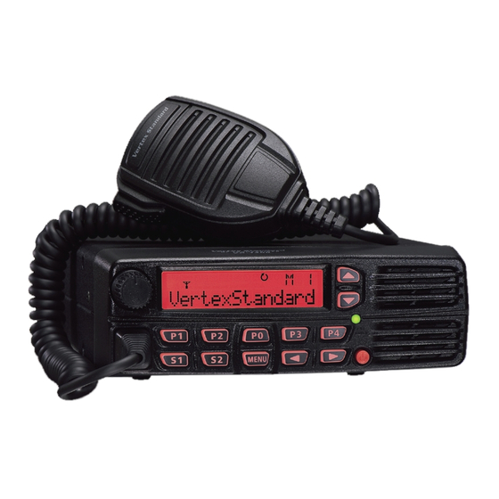
VX-1400
O
M
PERATING
ANUAL
MH-67
Hand Microphone is optional.
VERTEX STANDARD CO., LTD.
4-8-8 Nakameguro, Meguro-Ku, Tokyo 153-8644, Japan
VERTEX STANDARD
US Headquarters
10900 Walker Street, Cypress, CA 90630, U.S.A.
American Communication Systems
YAESU UK LTD.
™
Discover the Power of Communications
Unit 12, Sun Valley Business Park, Winnall Close
http://www.ameradio.com
TO ORDER – VISIT
Winchester, Hampshire, SO23 0LB, U.K.
VERTEX STANDARD HK LTD.
Unit 5, 20/F., Seaview Centre, 139-141 Hoi Bun Road,
Kwun Tong, Kowloon, Hong Kong
VERTEX STANDARD AUSTRALIA PTY., LTD.
Normanby Business Park, Unit 14/45 Normanby Road
Notting Hill 3168, Victoria, Australia
Advertisement
Table of Contents

Related Manuals for Vertex Standard VX-1400


Summary of Contents for Vertex Standard VX-1400
- Page 1 Winchester, Hampshire, SO23 0LB, U.K. VERTEX STANDARD HK LTD. Unit 5, 20/F., Seaview Centre, 139-141 Hoi Bun Road, Kwun Tong, Kowloon, Hong Kong VERTEX STANDARD AUSTRALIA PTY., LTD. Normanby Business Park, Unit 14/45 Normanby Road Notting Hill 3168, Victoria, Australia...
-
Page 2: Table Of Contents
Table of Contents VX-1400 Quick Reference Guide ....................1 Button Overview / Reset Procedure ....................2 General ............................3 Front Panel Control & Switches ....................4 Rear Panel Connections ......................... 6 Installation ............................7 Safety Precautions ........................7 Power Connections ......................7 Grounding for Electrical Safety ................... -
Page 3: Vx-1400 Quick Reference Guide
VX-1400 Q UICK EFERENCE UIDE You can do the basic operation of the VX-1400 according to the number order of the illustration below. Activates the function which Selects the operating frequency corresponds with that button. or memory channel. VOL K... -
Page 4: Button Overview / Reset Procedure
Press and hold the [ MENU ] button while turning the radio on. The confirmation message appears. Press the [ ] button to reset all settings to dealer default (press the [ ] button to cancel the reset procedure). VX-1400 O... -
Page 5: General
Land Mobile, Government, and Marine markets. The VX-1400 conforms with MIL-810 C, D, E, & F. The front panel is water resistance to IP54 specifications when in remote control operation using the optional RMK- 1400 Remote Mounting Kit with the MH-77 Water Resistance Hand Microphone. -
Page 6: Front Panel Control & Switches
[ P4 ] button: Press this button to select the operating mode. MENU Button Pressing this button activates the Menu mode which changes the configuration of the transceiver’s parameter. Button Pressing these buttons selects the frequency control method among “VFO mode”, “Memory mode”, and “ITU mode”. VX-1400 O... -
Page 7: Power Switch
ANEL ONTOL WITCHES POWER Switch This is the main on/off switch for the VX-1400. Press and hold this switch for 2 seconds to toggle the transceiver’s power on and off. Speaker The internal speaker is located here. TX/BUSY LED This indicator glows green when a signal is being received and red when transmitting. -
Page 8: Rear Panel Connections
ANEL ONNECTIONS DC IN 13.8V This is the main DC power input jack for the VX-1400. ANT Jack This PL-259 (“M” Type) connector is used for connection of the coaxial feedline from the antenna. When the optional FC-30 or FC-40 External Antenna Tuner is used, the RF interconnection cable from the FC-30 or FC-40 connects here, while the antenna wire or whip connects to the FC-30 or FC-40. -
Page 9: Installation
Power Connections The power connector for the VX-1400 must only be connected to a DC source providing 13.8 Volts DC (±15 %), and capable of at least 23 Amperes of current. Do not connect this apparatus to any other DC voltage, and never connect the DC power cable to an AC source of any kind. -
Page 10: Antenna Precautions
To ensure long life of the components, be certain to provide adequate ventilation around the cabinet of the VX-1400. The cooling system of the transceiver must be free to draw cool air in from the bottom of the transceiver and expel warm air from the rear of the transceiver. -
Page 11: Electromagnetic Compatibility And Rf Exposure
(RFI) suppression devices (such as ferrite cores) to minimize interference to your commu- nications caused by energy leakage from the computer. Although there is negligible radio frequency (RF) leakage from the VX-1400 transceiver itself, its antenna system should be located as far away from humans and animals as prac- ticable, so as to avoid the possibility of shock due to accidental contact with the antenna or excessive long-term exposure to RF energy. -
Page 12: Power Requirements And Basic Installation
NSTALLATION DC Power Connections The VX-1400 transceiver is designed for operation from 13.8 Volts DC, negative ground, with the DC source being capable of providing 23 Amperes of continuous current. For mobile applications, the fused (25-A) DC cable supplied with this transceiver may be used for making the power connections. - Page 13 Make certain that the battery terminal connections are tight, and remember to check them periodically for signs of loosening and/or corrosion. Make sure the POWER switch on the VX-1400 transceiver is off, and plug the DC cable into the INPUT jack on the rear panel of the transceiver.
-
Page 14: Mobile Mounting
Mobile Antenna Considerations The VX-1400 transceiver is designed for use with any antenna system providing a 50- Ohm resistive impedance at the desired operating frequency. While minor excursions from the 50-Ohm specification are of no consequence, the power amplifier’s protection cir-... - Page 15 FC-30 is from 17 Ohms to 150 Ohms. Interconnection guidelines may be found in the Operating Manual for the FC-30. MPORTANT When connecting optional equipment, you must turn off the transceiver. Note: The Mounting Bracket attached to the FC-30 is not used with the VX-1400. VX-1400 O...
-
Page 16: Mobile Station Grounding
RF grounding can nullify such filtering. Bonding the rear panel GND terminal of the VX-1400 transceiver to the vehicle or vessel’s ground system should clear up any such difficulties. -
Page 17: Base Station Installation
1030A AC Power Supply. The FP-1030A provides a regulated 13.8 V DC supply at up to 25-Ampere. Other models of DC power supplies may be used with the VX-1400, but the 13.8 V DC input voltage, 23-Ampere current capability, and DC cable polarity guidelines described previously must be strictly followed. -
Page 18: Base Station Antenna Considerations
Every effort must be made to ensure that the im- pedance of the antenna system utilized with the VX-1400 is as close as practicable to the specified 50-Ohm impedance value, and that mechanical and electrical component integ- rity are maintained at all times. - Page 19 HF antennas. Your dealer or installer should be able to assist you with all aspects of your antenna installation. Use high-quality coaxial cable for the lead-in to your VX-1400 transceiver. All efforts at providing an efficient antenna system will be wasted if poor quality, lossy coaxial cable is used.
-
Page 20: Base Station Grounding
NSTALLATION Base Station Grounding The VX-1400 HF transceiver, like any other HF communications apparatus, requires an effective ground system for maximum electrical safety and best communications effec- tiveness. A good ground system can contribute to station efficiency in a number of ways. - Page 21 Inspect the ground system - inside the station as well as outside - on a regular basis so as to ensure maximum performance and safety. Transceiver Linear Power Transceiver Linear Power Amplifier Supply Amplifier Supply "Daisy Chain" VX-1400 O...
-
Page 22: Operation
[ CLAR ] button (the [ P ROGRAM ] button which assigns the “Clarifier” MABLE function: the factory default is the [ P3 ] button) to activate the “Clarifier” function. The offset VX-1400 O... - Page 23 Press the Programmable Function ([ P0 ] ~ [ P4 ], [ S1 ] & [ S2 ]) buttons to activate the function which is corresponding with that button. Refer to page 42 for the details of the Programmable Function button. VX-1400 O...
-
Page 24: Frequency And Channel Selection
“ITU” which indicate ITU Marine Channel designator. Frequency and channel selection are very simple on the VX-1400: Select the desired channel grouping (VFO, Memory Channel, and ITU) by pressing the [ ] / [ ] button. The circulation of channel groups is “VFO”... -
Page 25: Vfo Mode
Otherwise, skip to the next step. Press the [ ENT ] key again to finalize the entry of the VFO frequency (frequen- cies). VX-1400 O... -
Page 26: Memory Channel Mode
Pressing and holding the [ UP ] or [ DWN ] key in for 1/2 second will initiate upward or downward scanning on the ITU Memory Channels, respectively. Releasing the [ UP ] or [ DWN ] key halts the scan. VX-1400 O... -
Page 27: Transmission
For CW (Morse Code telegraphy) in the A1A mode, begin sending using your tele- graph key or electronic keyer. The VX-1400 will automatically be placed in the trans- mit mode when you start to send, and will revert to the receive mode when you stop sending. -
Page 28: Antenna Tuning Procedures
[ P1 ] button). The two arrows of “ ” icon on the LCD display will blink, and the VX-1400 will transmit for a short time. Thereafter, the transceiver will return to the receive mode, and the “... -
Page 29: Dual Watch
” icon disap- pears and operation will revert to your original operating frequency. Note that your main operating channel can be changed during Dual Watch operation, but you cannot change channels while memory channel “1-001” is being checked for activity. VX-1400 O... -
Page 30: Encrypted Transmission/Reception
[ ENCRP ] button on the other station’s transceiver, then revert to encrypted operation immedi- ately by pressing the [ ENCRP ] button on your transceiver. VX-1400 O... -
Page 31: Mhz Emergency Channel Mode
In an Emergency, press the [ 2182 ] ([ S2 ]) button while pressing and holding in the [ ALARM ] ([ S1 ]) button. This VX-1400 will transmit the international marine dis- tress signal (alternating 1300 Hz and 2200 Hz tones) for 35 seconds. Press the [ ALARM ] ([ S1 ]) button (not the [ 2182 ] ([ S2 ]) button) to cancel the transmitted distress signal. -
Page 32: Selcall/Telcall Operation
ELCALL ELCALL PERATION The VX-1400’s Selcall feature provides six calling modes: Selcall The Selcall mode allows you to make an individual/group call using the indi- vidual ID (Identification) number assigned for each transceiver. Message Call The Message Call mode allows you to send a text message (up to 64 characters of text) to another station. -
Page 33: Selcall
Press the [ CALL ] key again to transmit the Selcall. Receiving a Selcall When the VX-1400 receives a Selcall matching your individual ID, a bell alarm will be heard, and the LCD will display the received (calling station’s) ID number. -
Page 34: Message Call
Press the [ CALL ] button again to transmit the Message Call. Receiving a Message Call When the VX-1400 receives a Message Call matching your individual ID, a bell alarm will be heard, and the “ ” icon will appear at the top center on the LCD, and the received (called station’s) ID number and the message will scroll across the dis-... -
Page 35: Position Request Call
Press the [ CALL ] button again to transmit the Position Request Call. Receiving a Position Request Call When the VX-1400 receives a Position Request Call matching your individual ID, the LCD will display the received (calling station’s) ID number; your radio will trans- mit your current position (Latitude/Longitude) automatically. -
Page 36: Position Send Call
Press the [ CALL ] button again to transmit the Position Send Call. Receiving a Position Send Call When the VX-1400 receives a Position Send Call matching your individual ID, a bell alarm will be heard, and the received (calling station’s) ID number, position (Lati- tude/Longitude), and time will scroll across the LCD. -
Page 37: Beacon Request Call
Press the [ ] / [ ] button to select “BCN REQ”. Press the [ CALL ] button again to transmit the Beacon Request Call. If the Beacon Request call is successful, the “Answer” signal from the called station will be heard. VX-1400 O... -
Page 38: Telcall
[ ] / [ ] (select number) buttons; finally press the [ TELCALL ] but- ton again. Press the [ TELCALL ] button again to transmit the TelCall. When the communication is finished, press the [ TELCALL ] button while holding in the PTT switch to send the “Hang-up” signal. VX-1400 O... - Page 39 ELCALL ELCALL PERATION VX-1400 O...
-
Page 40: Ale Operation
“ ” icon will be illuminated on the LCD display. After five seconds from the initial pressing of the [ ALE ] button, the VX-1400 will initiate the ALE scanner. If you wish to change the current ALE network, press the [ ] / [ ] button to select the desired network. -
Page 41: Sending An Ale Call With An Imbedded Message
“ ” icon will be illuminated on the LCD display. After five seconds from the initial pressing of the [ ALE ] button, the VX-1400 will initiate the ALE scanner. If you wish to change the current ALE network, press the [ ] / [ ] button to select the desired network. -
Page 42: Memory Channel Storage
EMORY HANNEL TORAGE The VX-1400 allows the user or dispatcher to store the frequency and operating mode into the desired Memory Bank. Press the [ ] / [ ] button to recall the Memory Bank which wants to store the data. - Page 43 [ ] / [ ] button to select the desired logic (“HIGH” or “LOW”). Otherwise, skip to the next step. Press the [ MW ] button to store the frequency and other data into the selected memory chan- nel. VX-1400 O...
-
Page 44: Programmable Function (Pf) Buttons
UNCTION UTTON The VX-1400 includes seven Programmable Function ([ S1 ] , [ S2 ] & [ P0 ] ~ [ P4 ]) but- tons. The Programmable Function button functions can be customized via programming by your VERTEX STANDARD dealer, to meet your communications/network require- ments. - Page 45 ENCRP FILTER LOCK MODE P.BACK RCV MSG RF PWR SCAN SCAN SET SELCALL STEP TELCALL TUNE TUNE ALL VOICE ENHANCER AUX MOMENTALY AUX TOGGLE ALARM — — — — — — 2182 — — — — — — VX-1400 O...
- Page 46 “ATT ON (PRE AMP OFF)” “ATT ON (PRE AMP OFF)” ..“PRE AMP ON (ATT OFF)” “ATT & AMP OFF” CALL Press the assigned programmable button to transmit a Selcall (or ALE) while operating in the Selcall (or ALE) mode. VX-1400 O...
- Page 47 Press the assigned programmable button to toggle the Encryption feature “on” and “off”. When the Encryption feature is activated, the “ ” icon will appear in the LCD. Press the assigned programmable button to send an “Entry” command. Press the assigned programmable button to send an “Escape (Cancel)” command. VX-1400 O...
- Page 48 “Medium”, and “High”). The “L” icon will appear at the left of the display while operat- ing on the “Low Power” setting, and the “M” icon will appear at the left of the display while operating on “Medium Power” setting. VX-1400 O...
- Page 49 Press the assigned programmable button to activate the upward scan. When the scanner is activated, press the [ ] / [ ] button to change the direction of the scanner to downward or upward, respectively. In the memory mode, the VX-1400 scan only the memory channel which the “...
- Page 50 Press the assigned programmable button to instantly set the transceiver to 2182 kHz in the H3E mode. Pressing both this button and the [ ALARM ] button transmits the International Marine Distress Signal. Important Note: This function is assigned to only [ S2 ] button. VX-1400 O...
-
Page 51: Installation Of The Option
Replace the Top Cover with its eight screws while being careful that any wires are not pinched. Reconnect the DC Power Cable, Microphone, and Antenna to the transceiver. This completes installation of the ALE-2 Automatic Link Establishment Unit. MAIN Unit J4006 VX-1400 O... -
Page 52: Ct-139 Accessory Cable
Replace the Top Cover with its eight screws while being careful so that any wires are not pinched. Reconnect the DC Power Cable, Microphone, and Antenna to the transceiver. This completes installation of the CT-139 Accessory Cable. Flat J4013 Ground Cable J4012 13-pin Connector 12-pin Connector MAIN Unit VX-1400 O... - Page 53 This pin is closed to ground while the transceiver’s squelch is closed. AUX I/O-4 This pin feature can be programmed via the CE111 programmer. The accessible voltage is CMOS Logic Level (H = 5 V). This pin is connected to the transceiver’s chassis. VX-1400 O...
-
Page 54: Accessories And Options
CT-104A PC Programming Cable VPL-1 PC Programming Cable 1: The VOX and Encryption feature of the transceiver does not work with MD-12 2: The [ UP ] / [ DWN ] key does not work in this transceiver. VX-1400 O... - Page 56 Copyright 2009 Printed in Japan VERTEX STANDARD CO., LTD. All rights reserved. 0910k-AE No portion of this manual may be reproduced without the permission of VERTEX STANDARD CO., LTD. E C 0 9 1 H 1 0 1...
Need help?
Do you have a question about the VX-1400 and is the answer not in the manual?
Questions and answers