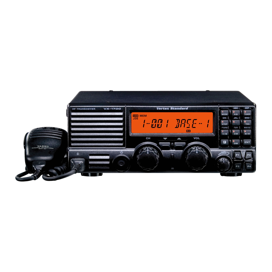
Vertex Standard VX-1700 Operating Manual
Hf transceiver
Hide thumbs
Also See for VX-1700:
- Service manual (136 pages) ,
- Reference book (10 pages) ,
- Alignment manual (8 pages)

Related Manuals for Vertex Standard VX-1700


Summary of Contents for Vertex Standard VX-1700
- Page 1 VX-1700 Operating Manual Vertex Standard LMR, Inc. 4-8-8 Nakameguro, Meguro-Ku, Tokyo 153-8644, Japan...
-
Page 2: Table Of Contents
Table of Contents General ................. 1 Operation ..............14 Startup Procedures ..........14 Front Panel Control & Switches ........ 2 Rear Panel Connections ..........4 Reception ............... 14 Frequency and Channel Selection ......15 Installation ..............5 Safety Precautions ........... 5 VFO Mode ............ -
Page 3: General
J3E (USB or LSB), A1A, A3E, and H3E (only on 2182 cally selects the channel with the best LQA (Link Quality kHz in the Marine version), making the VX-1700 ideal Analysis) score from the programmed channels. for a wide variety of voice, telegraphy, and many data com- munication applications. -
Page 4: Front Panel Control & Switches
POWER Switch weaker signals to be heard. This is the main on/off switch for the VX-1700. Press When a signal or noise breaks through the squelch and hold this switch for one second to toggle the “threshold,”... - Page 5 Toggles the Display intensity between “High” and “Low.” Engages the Set (Menu) mode. Activates the “Secondary” key function. Disables the “Secondary” key function. Activates the “Alternate” key function. Disables the “Alternate” key function. VX-1700 O Page 3 PERATING ANUAL...
-
Page 6: Rear Panel Connections
ANEL ONNECTIONS INPUT ( 13.8 V ) TUNER Jack This is the main DC power input jack for the VX-1700. This 8-pin mini-DIN jack is for interconnection to the optional FC-30 or FC-40 External Antenna Tuner. ANT Jack ACC Jack This PL-259 (“M”... -
Page 7: Installation
Power Connections rotator cable (if used) according to the arrestor’s instruc- The power connector for the VX-1700 must only be con- tions. nected to a DC source providing 13.8 Volts DC (±15 %), In the event of an approaching electrical storm, discon- and capable of at least 20 Amperes of current. -
Page 8: Electromagnetic Compatibility And Rf Exposure
Although there is negligible radio frequency (RF) leakage dealer, if the unit was purchased over-the-counter) so as to from the VX-1700 transceiver itself, its antenna system get instructions regarding the prompt resolution of the should be located as far away from humans and animals as damage situation. -
Page 9: Power Requirements And Basic Installation
Route the DC Make sure the POWER switch on the VX-1700 trans- cable as far away from ignition cables as possible, and cut ceiver is off, and plug the DC cable into the INPUT off any extra cable (from the battery end) to minimize volt- jack on the rear panel of the transceiver. -
Page 10: Mobile Mounting
The FC-40 should be located at or near the base of the Mobile Antenna Considerations antenna, so as to minimize losses and stray radiation. The The VX-1700 transceiver is designed for use with any short lead-in wire from the whip must be securely bonded antenna system providing a 50-Ohm resistive impedance both to the FC-40 and the antenna (whip or wire), and the at the desired operating frequency. -
Page 11: Mobile Station Grounding
Bonding the rear panel GND in some installations, to provide a direct ground connec- terminal of the VX-1700 transceiver to the vehicle or tion at the mounting location of the transceiver. Due to vessel’s ground system should clear up any such difficul- unexpected resonances which may naturally occur in any ties. -
Page 12: Base Station Installation
Other models of DC power supplies may be used with the of 13.8 V ±15%. If using a power supply other than the VX-1700, but the 13.8 V DC input voltage, 20-Ampere FP-1030A, ensure that the DC supply connector to the current capability, and DC cable polarity guidelines de- transceiver matches the VX-1700 wiring configuration. -
Page 13: Base Station Antenna Considerations
VX-1700 is as close as practicable to the specified a profound impact on the favored launch angle for the main 50-Ohm impedance value, and that mechanical and elec- radiation lobe from the antenna at a particular frequency. -
Page 14: Base Station Grounding
Excellent reference texts and computer software are avail- able for the design and optimization of HF antennas. Your The VX-1700 HF transceiver, like any other HF commu- dealer or installer should be able to assist you with all nications apparatus, requires an effective ground system aspects of your antenna installation. - Page 15 NSTALLATION VX-1700 O Page 13 PERATING ANUAL...
-
Page 16: Operation
[ 0 ( DIM )] key again return to the LCD display to nominal brightness level. To turn the internal speaker (or external speaker, if used) off, press the [ P4 ] key. Press the [ P4 ] key again to restore the speaker audio. VX-1700 O Page 14 PERATING ANUAL... -
Page 17: Frequency And Channel Selection
PERATION REQUENCY AND HANNEL ELECTION The VX-1700 includes the following frequency selection VFO Mode capabilities: Rotate the CH Selector knob to select the operating A VFO (Variable Frequency Oscillator) System frequency. ITU Marine Channel Memory Channel A one-touch (2.182 MHz) Emergency Channel Memory, which places the transceiver on 2.182... -
Page 18: Memory Channel Mode
In an Emergency, press the [ 2182 ] button while press- Channel Bank provided. The operating mode is auto- ing and holding in the [ ALARM ] button. This VX-1700 matically selected, and can not be changed. will transmit the international marine distress signal (alternating 1300 Hz and 2200 Hz tones) for 35 sec- onds. -
Page 19: Transmission
” icon on the LCD Display will blink, and vert to the receive mode when you stop sending. As the VX-1700 will transmit for a short time. Thereafter, you send, a “Sidetone” audio generator allows you to the transceiver will return to the receive mode, and the monitor your sending. -
Page 20: Dual Watch
CH Selector knob until “TIME” is displayed. Now press the [ 8 ( DW )] key again to return to the normal If the VX-1700 is in the “Carrier Drop” mode, the trans- display. ceiver will hold on memory channel “1-001” until the transmission ceases. -
Page 21: Encrypted Transmission/Reception
[ ENCR ] key on the other station’s transceiver, then revert to encrypted operation immediately by pressing the [ ENCR ] key on your transceiver. VX-1700 O Page 19 PERATING ANUAL... -
Page 22: Selcall/Telcall Operation
ELCALL ELCALL PERATION The VX-1700’s Selcall feature provides six calling modes: ELCALL Selcall The Selcall mode allows you to make an individual/group The Selcall mode allows you to make an individual/ call using an individual ID (Identification) assigned to each group call using the individual ID (Identification) transceiver in your group or fleet. -
Page 23: Message Call
The Message Call mode allows you to send a text message Receiving a Message Call (up to 64 characters of text) to a specific station. When the VX-1700 receives a Message Call matching your individual ID, a bell alarm will be heard, and the Preparation “... -
Page 24: Position Request Call
.” Receiving a Position Request Call Press the [ CALL ] key again to transmit the Position When the VX-1700 receives a Position Request Call Send Call. matching your individual ID, the LCD will display the received (calling station’s) ID number; your radio will... -
Page 25: Beacon Request Call
[ TELCALL ] key while holding in the PTT switch to Request Call. send the “Hang-up” signal. If the Beacon Request call is successful, the “Answer” signal from the called station will be heard. VX-1700 O Page 23 PERATING ANUAL... -
Page 26: Ale Operation
Press the [ 7 ( V/M )] key, as needed, to select the Memory network. After five seconds from the initial pressing Channel mode. of the [ ALE ] key, the VX-1700 will initiate the ALE Press the [ AEL ] key momentarily to activate the ALE scanner. -
Page 27: Memory Channel Storage
Example 3: Press the [ 0 ( DIM )] key to toggle the J3E(LSB), J2B(USB/LSB), A1A(CW), and A3E(AM). characters “0” and “space.” Press the [ ENT ] key momentarily to lock the fre- quencies, mode, and “Tag” into the memory. VX-1700 O Page 25 PERATING ANUAL... -
Page 28: Programmable Function (Pf) Keys
PF K ROGRAMMABLE UNCTION CH 1 - CH 4 The VX-1700 includes four Programmable Function (P1 ~ P4) Keys. The Programmable Function button functions Press the assigned programmable key to recall the Dealer can be customized, via programming by your VERTEX... - Page 29 AUX PRS TO H Press the assigned programmable key to turn the optional accessory port “2” to “High.” AUX PRS TO L Press the assigned programmable key to turn the optional accessory port “1” to “Low.” VX-1700 O Page 27 PERATING ANUAL...
- Page 30 VX-1700 O Page 28 PERATING ANUAL...
- Page 32 Copyright 2012 Vertex Standard LMR, Inc. All rights reserved No portion of this manual may be reproduced without the permission of Vertex Standard LMR, Inc. Printed in Japan.
Need help?
Do you have a question about the VX-1700 and is the answer not in the manual?
Questions and answers