Table of Contents
Advertisement
Quick Links
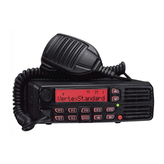
VX-1400 Series
HF Multi Mode Mobile Radio
Service Manual
©2009 VERTEX STANDARD CO., LTD.
This manual provides the technical information necessary for
servicing the VX-1400 HF Transceiver.
Servicing this equipment requires expertise in handing sur-
face-mount chip components. Attempts by non-qualified per-
sons to service this equipment may result in permanent dam-
age not covered by the warranty, and may be illegal in some
countries.
Two PCB layout diagrams are provided for each double-sided
board in this transceiver. Each side of the board is referred to
by the type of the majority of components installed on that side ("Side A" or "Side B"). In most cases one side
has only chip components (surface-mount devices), and the other has either a mixture of both chip and leaded
components (trimmers, coils, electrolytic capacitors, ICs, etc.), or leaded components only.
As described in the pages to follow, the advanced microprocessor design of the VX-1400 Transceiver allows a
complete alignment of this transceiver to be performed without opening the case of the radio; all adjustments
can be performed from the front panel, using the "Alignment Mode" menu.
While we believe the information in this manual to be correct, VERTEX STANDARD assumes no liability for
damage that may occur as a result of typographical or other errors that may be present. Your cooperation in
pointing out any inconsistencies in the technical information would be appreciated.
1) This transceiver was assembled using Pb (lead) free solder, based on the RoHS specification.
Only lead-free solder (Alloy Composition: Sn-3.0Ag-0.5Cu) should be used for repairs performed on this apparatus. The
solder stated above utilizes the alloy composition required for compliance with the lead-free specification, and any solder
with the above alloy composition may be used.
2) Risk of explosion if battery is replaced by an incorrect type. Dispose of used batteries according to the instructions.
Specifications ...................................................................................................................................................... 2
Exploded View & Miscellaneous Parts .......................................................................................................... 3
Block Diagram ..................................................................................................................................................... 5
Connection Diagram .......................................................................................................................................... 6
Alignment ............................................................................................................................................................ 7
Board Units (Schematics, Layouts & Parts)
PANEL Unit ................................................................................................................................................ 15
MAIN Unit .................................................................................................................................................. 23
PA Unit ........................................................................................................................................................ 47
ALE-2 Unit (Option) .................................................................................................................................. 59
VX-1400 Series Service Manual
All manuals and user guides at all-guides.com
EC091H90A
Important Note
Contents
VERTEX STANDARD CO., LTD.
4-8-8 Nakameguro, Meguro-Ku, Tokyo 153-8644, Japan
VERTEX STANDARD
US Headquarters
10900 Walker Street, Cypress, CA 90630, U.S.A.
YAESU UK LTD.
Unit 12, Sun Valley Business Park, Winnall Close
Winchester, Hampshire, SO23 0LB, U.K.
VERTEX STANDARD HK LTD.
Unit 5, 20/F., Seaview Centre, 139-141 Hoi Bun Road,
Kwun Tong, Kowloon, Hong Kong
VERTEX STANDARD AUSTRALIA PTY., LTD.
Normanby Business Park, Unit 14/45 Normanby Road
Notting Hill 3168, Victoria, Australia
1
Advertisement
Table of Contents

Related Manuals for Vertex Standard VX-1400 Series


Summary of Contents for Vertex Standard VX-1400 Series
-
Page 1: Table Of Contents
“Alignment Mode” menu. While we believe the information in this manual to be correct, VERTEX STANDARD assumes no liability for damage that may occur as a result of typographical or other errors that may be present. Your cooperation in pointing out any inconsistencies in the technical information would be appreciated. -
Page 2: Specifications
< -6 dB (300 to 2400 Hz) Occupied Bandwidth: < 0.5 kHz (A1A) < 3.0 kHz (J2B/J3E/H3E) < 6.0 kHz (A3E) Microphone Impedance: 200 Ohm - 10 k-Ohm, (600 Ohm: Nominal) Specifications are subject to change without notice or obligation. VX-1400 Series Service Manual... -
Page 3: Exploded View & Miscellaneous Parts
HEX SOCKET BOLT HSM4X16NI RA0940400 RA1129900 U72004002 TOOTHED LOCK WASHER OW4NI O RING PANEL ASSY (W/ SP NET, LED GUIDE, WINDOW) S4000055 CASE LEG (x4 pcs) Non-designated parts are available only as part of a designated assembly. VX-1400 Series Service Manual... - Page 4 All manuals and user guides at all-guides.com Exploded View & Miscellaneous Parts VX-1400 Series Service Manual...
-
Page 5: Block Diagram
All manuals and user guides at all-guides.com Block Diagram VX-1400 Series Service Manual... -
Page 6: Connection Diagram
All manuals and user guides at all-guides.com Connection Diagram VX-1400 Series Service Manual... -
Page 7: Alignment
Vertex Standard VPL-1 or FIF-10 + CT-104A Pro- the warranty policy. gramming Cable & CE111 Programming Soft- Vertex Standard must reserve the right to change circuits ware and alignment procedures in the interest of improved performance, without notifying owners. - Page 8 RX IF Circuit (SSB/CW) Connect the VX-1400 to a computer with a Clone cable. Connect the AF millivoltmeter and 4 Ohm dummy load to the EXT SPKR jack. Connect the RF Signal Generator to the "ANT" jack, VX-1400 Series Service Manual...
- Page 9 Press the [ ] / [ ] button to select the "memory chan- + 5V nel 017". Adjust T4016 on the MAIN-Unit for maximum deflec- tion on the AF millivoltmeter. HOOK MIC J INOUT T4011 TP4039 TP4058 T4017 T4014 T4013 T4012 T4015 L4072 T4018 J4002 MAIN U VX-1400 Series Service Manual...
- Page 10 DC ammeter reading is 0.5 A ± 50 mA. Release the PTT button. Press the PTT button; adjust VR5003 on the PA Unit so the DC ammeter reading is 1.0 A ± 50 mA. Release the PTT button. VX-1400 Series Service Manual...
- Page 11 All manuals and user guides at all-guides.com Alignment VR5002 J5005 VR5005 VR5004 VR5001 J5007 VR5003 L5008 TP5028 TC5001 PA U VX-1400 Series Service Manual...
- Page 12 25 W (± 2 W) 4PO-L 10 W (± 1 W) Press and hold in the [MENU] button for 2 seconds to CL_DATA save the new settings and exit from the alignment CL_SW mode. + 5V HOOK MIC J INOUT VX-1400 Series Service Manual...
- Page 13 Press the PTT switch, then press the [ ] / [ ] key for 50 W on the PO meter of the VX-1400. Release the PTT switch. Press and hold in the [MENU] button for 2 seconds to save the new settings and exit from the alignment mode. VX-1400 Series Service Manual...
- Page 14 All manuals and user guides at all-guides.com Alignment Note VX-1400 Series Service Manual...
-
Page 15: Panel Unit
All manuals and user guides at all-guides.com PANEL Unit Circuit Diagram VX-1400 Series Service Manual... - Page 16 All manuals and user guides at all-guides.com PANEL Unit Note VX-1400 Series Service Manual...
- Page 17 All manuals and user guides at all-guides.com PANEL Unit Parts Layout (Side A) DTC114TE (04) (Q3018, 3019, 3021, 3022) VX-1400 Series Service Manual...
- Page 18 2SC4047(ZY) TC7S00F(E1) DTC114TE (Q3001) (Q3002, 3007) (Q3004) (Q3005) (Q3006) (Q3009, 3020, 3023) UMD5N RTQ030P02(LE) 25AA512T-I/SN UMW1(W1) 2SA1576A(F141) 2SB1132(BA) HD64F2268TF20 (Q3010) (Q3011) (Q3012) (Q3013, 3015) (Q3014) (Q3016) (Q3008) NJU6624CFG1-02 (Q3017) DA221(K) DAN222(N) (D3006, 3008, 3010, 3011) (D3013) VX-1400 Series Service Manual...
- Page 19 G2070768 D 3032 LED BRPG1204W(TAPE) G2070820 D 3033 LED SML-210MTT86 G2070524 D 3034 LED TLOU1020(T14.F) G2070990 D 3035 LED TLOU1020(T14.F) G2070990 D 3036 LED TLOU1020(T14.F) G2070990 D 3037 LED TLOU1020(T14.F) G2070990 D 3038 LED TLOU1020(T14.F) G2070990 VX-1400 Series Service Manual...
- Page 20 R 3046 CHIP RES. 1/16W 5% RMC1/16S 102JTH J24189025 R 3047 CHIP RES. 1/16W 5% RMC1/16S 102JTH J24189025 R 3048 CHIP RES. 1/16W 5% RMC1/16S 101JTH J24189013 R 3049 CHIP RES. 1/16W 5% RMC1/16S 102JTH J24189025 VX-1400 Series Service Manual...
- Page 21 RH96N1100 19F B203 RY8855 J60800303 X 3001 XTAL TSS-6035B 19.82MHz 19.820MHZ H0103262A LIGHT GUIDE (LCD) RA1137900 HOLDER (LCDGUIDE) RA1139800 REFLECTOR SHEET RA1142900 RUBBER CONNECTOR (LCD) RA1130800 LCD HOLDER RA1130900 SPONGE RUBBER (LCD) RA1142700 DIFFUSER SHEET RA1167000 VX-1400 Series Service Manual...
- Page 22 All manuals and user guides at all-guides.com PANEL Unit Note VX-1400 Series Service Manual...
- Page 23 All manuals and user guides at all-guides.com MAIN Unit Circuit Diagram VX-1400 Series Service Manual...
- Page 24 (D4036) (Q4013, 4014) DAN202U(N) TC7S04FU(E5) (D4005, 4041) (Q4079, 4095) DAN217U(A7) 2SK210(YG) (D4046, 4047) (Q4081, 4093, 4094) HSB88WS 2SK520(K41) (D4034) (Q4020, 4029) 2SK1740 (Q4036, 4037, 4040, 4041) HZM7.5NB3 (D 4031, 4037) HZM27WA (27A) (D4058) DAP236U (X) (D4048) VX-1400 Series Service Manual...
- Page 25 (Q4047, 4049, 4054, 4056) (Q4061, 4066, 4070, 4073, 4074, 4076) TC74VHCT574AFT (Q4024, 4025, 4026, 4027) LM2904PWR (Q4046, 4050, 4052) TDA1519CTH (Q4096) UPC29M08T (Q4011) TD62783AFNG (Q4009) AK4528VF (Q4087) 2SJ106GR(VY) (Q4099) BD12KA5FP-E2 (Q4039) BU4052BCF-E2 (Q4057) AK4550VT (Q4069) TC7W32F (Q4022) ADF4001BRUZ (Q4092) VX-1400 Series Service Manual...
- Page 26 All manuals and user guides at all-guides.com MAIN Unit Parts Layout (Side B) TDA1519CTH (Q4096) VX-1400 Series Service Manual...
-
Page 27: Main Unit
K22174839 C 4074 CHIP CAP. 0.022uF GRM188B11H223KA01D K22174839 C 4075 CHIP CAP. 0.022uF GRM188B11H223KA01D K22174839 C 4076 CHIP CAP. 0.022uF GRM188B11H223KA01D K22174839 C 4077 CHIP CAP. 0.022uF GRM188B11H223KA01D K22174839 C 4078 CHIP CAP. 0.022uF GRM188B11H223KA01D K22174839 VX-1400 Series Service Manual... - Page 28 GRM1882C1H150JA01D K22174215 C 4133 CHIP CAP. 12pF GRM1882C1H120JA01D K22174213 C 4134 CHIP CAP. GRM1882C1H8R0DZ01D K22174209 C 4135 CHIP CAP. 0.1uF GRM42-6B104K50PT K22171820 C 4136 CHIP CAP. 220pF GRM1882C1H221JA01D K22174243 C 4137 CHIP CAP. 150pF GRM1882C1H151JA01D K22174239 VX-1400 Series Service Manual...
- Page 29 K78120031 C 4193 CHIP CAP. 56pF GRM1882C1H560JA01D K22174229 C 4194 CHIP TA.CAP. 10uF TEESVA1A106M8R K78100028 C 4195 CHIP CAP. 120pF GRM1882C1H121JA01D K22174237 C 4196 CHIP CAP. 0.01uF GRM188B11H103KA01D K22174823 C 4197 CHIP CAP. 0.022uF GRM188B11H223KA01D K22174839 VX-1400 Series Service Manual...
- Page 30 GRM188B11H223KA01D K22174839 C 4256 CHIP CAP. 0.1uF GRM188B11C104KA01D K22124805 C 4257 CHIP CAP. 15pF GRM1882C1H150JA01D K22174215 C 4258 CHIP CAP. 0.022uF GRM188B11H223KA01D K22174839 C 4259 CHIP TA.CAP. TEESVA1C105M8R K78120009 C 4260 CHIP CAP. 0.01uF GRM188B11H103KA01D K22174823 VX-1400 Series Service Manual...
- Page 31 K22174227 C 4317 CHIP CAP. 47pF GRM1882C1H470JA01D K22174227 C 4318 CHIP CAP. 0.1uF GRM188B11C104KA01D K22124805 C 4319 CHIP TA.CAP. 10uF TEESVA1A106M8R K78100028 C 4320 CHIP CAP. 0.1uF GRM188B11C104KA01D K22124805 C 4321 CHIP TA.CAP. 4.7uF TEESVB21E475M8R K78140019 VX-1400 Series Service Manual...
- Page 32 K22174830 C 4376 CHIP CAP. 0.001uF GRM188B11H102KA01D K22174821 C 4378 CHIP CAP. 0.01uF GRM188B11H103KA01D K22174823 C 4379 CHIP CAP. 0.022uF GRM188B11H223KA01D K22174839 C 4380 CHIP CAP. 22pF GRM1882C1H220JA01D K22174219 C 4381 CHIP CAP. 22pF GRM1882C1H220JA01D K22174219 VX-1400 Series Service Manual...
- Page 33 K22174823 C 4438 CHIP CAP. 0.01uF GRM188B11H103KA01D K22174823 C 4439 CHIP CAP. 0.01uF GRM188B11H103KA01D K22174823 C 4440 CHIP CAP. 10pF GRM1883U1H100JZ01D K22174301 C 4441 CHIP CAP. 10pF GRM1882C1H100JA01D K22174211 C 4442 CHIP CAP. 24pF GRM1882C1H240JZ01D K22174220 VX-1400 Series Service Manual...
- Page 34 ECHU1C123JX5 K57120031 C 4503 AL.ELECTRO.CAP. 100uF RV2-4V101MU-R K48060004 C 4504 CHIP CAP. 82pF GRM1882C1H820JA01D K22174233 C 4505 CHIP CAP. 82pF GRM1882C1H820JA01D K22174233 C 4506 CHIP CAP. 68pF GRM1882C1H680JA01D K22174231 C 4507 CHIP CAP. 0.0022uF GRM188B11H222KA01D K22174813 VX-1400 Series Service Manual...
- Page 35 G2070452 D 4058 DIODE HZM27WA TR-E G2070530 D 4059 DIODE D1F60-5053 G2071240 D 4060 DIODE RLS245 TE-11 G2070834 D 4061 DIODE RLS245 TE-11 G2070834 D 4062 DIODE RLS245 TE-11 G2070834 D 4063 DIODE RLS245 TE-11 G2070834 VX-1400 Series Service Manual...
- Page 36 L1690082 L 4043 CHIP COIL 2.2uH C2520C-2R2G-RA L1691313 L 4044 CHIP COIL 1.5uH C2520C-1R5G-RA L1691311 L 4046 CHIP COIL 2.2uH C2520C-2R2K-RK L1690731 L 4047 CHIP COIL 4.7uH C2520C-4R7G-RA L1691317 L 4048 CHIP COIL 0.1uH C2520C-R10J L1690544 VX-1400 Series Service Manual...
- Page 37 Q 4023 TRANSISTOR 2SC3357-T2 RF G3333577F Q 4024 IC TC74VHCT574AFT(EL) G1094710 Q 4025 IC TC74VHCT574AFT(EL) G1094710 Q 4026 IC TC74VHCT574AFT(EL) G1094710 Q 4027 IC TC74VHCT574AFT(EL) G1094710 Q 4028 TRANSISTOR 2SC2714Y(TE85R.F) G3327147Y Q 4029 FET 2SK520-T2B K41 G3805207A VX-1400 Series Service Manual...
- Page 38 Q 4096 IC TDA1519CTH G1093778 Q 4097 POLY SWITCH MINISMDC0505-02 G9090143 Q 4098 TRANSISTOR 2SD2211 T100 QR G3422117Q Q 4099 FET 2SJ106GR(TE85L.F) G3701068G R 4001 CHIP RES. 1/16W 5% RMC1/16 271JATP J24185271 : Please contact VERTEX STANDARD VX-1400 Series Service Manual...
- Page 39 R 4057 CHIP RES. 100k 1/16W 5% RMC1/16 104JATP J24185104 R 4058 CHIP RES. 1/16W 5% RMC1/16 681JATP J24185681 R 4059 CHIP RES. 1/16W 5% RMC1/16 000JATP J24185000 R 4060 CHIP RES. 1/16W 5% RMC1/16 220JATP J24185220 VX-1400 Series Service Manual...
- Page 40 J24185332 R 4119 CHIP RES. 1/16W 5% RMC1/16 331JATP J24185331 R 4120 CHIP RES. 1/16W 5% RMC1/16 101JATP J24185101 R 4121 CHIP RES. 1/8W RMC1/8T 121J J24215121 R 4122 CHIP RES. 1/16W 5% RMC1/16 470JATP J24185470 VX-1400 Series Service Manual...
- Page 41 R 4180 CHIP RES. 1/16W 5% RMC1/16 101JATP J24185101 R 4181 CHIP RES. 1/16W 5% RMC1/16 473JATP J24185473 R 4182 CHIP RES. 1/16W 5% RMC1/16 683JATP J24185683 R 4183 CHIP RES. 1/16W 5% RMC1/16 102JATP J24185102 VX-1400 Series Service Manual...
- Page 42 R 4239 CHIP RES. 1/16W 5% RMC1/16 560JATP J24185560 R 4240 CHIP RES. 1/16W 5% RMC1/16 221JATP J24185221 R 4241 CHIP RES. 4.7k 1/16W 5% RMC1/16 472JATP J24185472 R 4242 CHIP RES. 4.7k 1/16W 5% RMC1/16 472JATP J24185472 VX-1400 Series Service Manual...
- Page 43 R 4301 CHIP RES. 1/16W 5% RMC1/16 221JATP J24185221 R 4302 CHIP RES. 4.7k 1/16W 5% RMC1/16 472JATP J24185472 R 4303 CHIP RES. 100k 1/16W 5% RMC1/16 104JATP J24185104 R 4305 CHIP RES. 1.8k 1/16W 5% RMC1/16 182JATP J24185182 VX-1400 Series Service Manual...
- Page 44 R 4362 CHIP RES. 1/4W RMC1/4 471JATP J24245471 R 4363 CHIP RES. 100k 1/16W 5% RMC1/16 104JATP J24185104 R 4364 CHIP RES. 1/16W 5% RMC1/16 221JATP J24185221 R 4365 CHIP RES. 1/16W 5% RMC1/16 221JATP J24185221 VX-1400 Series Service Manual...
- Page 45 T 4014 COIL 05RF 74.62MHz 74.62M 030812396C L0022854 T 4015 COIL 05RF M5-N1 R12-T661Y L0022674 T 4016 COIL 05RF 74.62MHz 74.62M 030812396C L0022854 T 4017 COIL 05RF 100M 010812300A L0022779 T 4018 COIL 10RF 0.36U L0021400A VX-1400 Series Service Manual...
- Page 46 TTS14VSB-A8 22.625MHZ H9501210 XF4001 XTAL FILTER MFT67N 67.899MHZ H1102406 SHIELD CASE (20X51) RA0830700 SHIELD CASE COVER (20X51) RA0830800 SHIELD CASE VCO RA1153400 SHIELD CASE VCO RA1153400 SHIELD CASE COVER (VCO) RA1153500 SHIELD CASE COVER (VCO) RA1153500 VX-1400 Series Service Manual...
- Page 47 All manuals and user guides at all-guides.com PA Unit Circuit Diagram VX-1400 Series Service Manual...
- Page 48 All manuals and user guides at all-guides.com PA Unit VX-1400 Series Service Manual...
- Page 49 PA Unit Parts Layout (Side A) RD06HHF1-01 RD100HHF1-101 (Q5002) (Q5011, 5012) RD16HHF1 (Q5007, 5008) DTD123YK (F62) HA178L09UA (Q 5001, 5003) (Q5004) TA75S01F(SA) UMD5N (Q5005) (Q5006) DTC124GUA (K25) DTC114TE (04) (Q 5009) (Q5010) DAN202U (N) (D5010, 5011) VX-1400 Series Service Manual...
- Page 50 All manuals and user guides at all-guides.com PA Unit Parts Layout (Side B) VX-1400 Series Service Manual...
-
Page 51: Pa Unit
K22170823 C 5068 CHIP CAP. 0.047uF GRM21BB11H473KA01L K22170823 C 5069 CHIP CAP. 0.01uF GRM188B11H103KA01D K22174823 C 5070 CHIP CAP. 0.047uF GRM188B11E473KA01D K22144811 C 5071 CHIP CAP. 180pF GRM2162C1H181JA01D K22170241 C 5072 CHIP CAP. 180pF GRM2162C1H181JA01D K22170241 VX-1400 Series Service Manual... - Page 52 10pF 200V GRM2192C2D100JV01D K22230216 C 5147 CHIP CAP. 82pF 200V GRM21B2C2D820JV01L K22230227 C 5148 CHIP CAP. 68pF 200V GRM21B2C2D680JV01L K22230226 C 5149 CHIP CAP. 100pF 500V 1206N101J501LT K22278221 C 5151 CHIP CAP. 27pF 200V GRM2192C2D270JV01D K22230221 VX-1400 Series Service Manual...
- Page 53 10pF 200V GRM2192C2D100JV01D K22230216 C 5209 CHIP CAP. 820pF 500V 1206N821J501LT K22278232 C 5210 CHIP CAP. 680pF 500V 1206N681J501LT K22278231 C 5211 CHIP CAP. 100pF 500V 1206N101J501LT K22278221 C 5212 CHIP CAP. 560pF 500V 1206N561J501LT K22278230 VX-1400 Series Service Manual...
- Page 54 D 5021 DIODE MA729-(TX) G2070320 D 5022 DIODE MA729-(TX) G2070320 D 5023 SURGE ABSORBER RHCA-301Q43U Q9000827 J 5001 CONNECTOR B2B-EH(LF)(SN) P0090666 J 5002 CONNECTOR TMP-S01X-C1 P1091254 J 5003 CONNECTOR 30FLT-SM2-TB(LF)(SN)(M) P1091142 J 5004 CONNECTOR B2B-EH(LF)(SN) P0090666 VX-1400 Series Service Manual...
- Page 55 1/10W 5% RMC1/10T 180J J24205180 R 5003 CHIP RES. 1/10W 5% RMC1/10T 331J J24205331 R 5004 CHIP RES. RMC1 330JTE J24305330 R 5005 CHIP RES. RMC1 330JTE J24305330 R 5006 CHIP RES. 1/16W 5% RMC1/16 821JATP J24185821 VX-1400 Series Service Manual...
- Page 56 RMC1/16 102JATP J24185102 R 5077 CHIP RES. 4.7k 1/16W 5% RMC1/16 472JATP J24185472 R 5079 CHIP RES. 1/2W RMC1/2 560JTE J24275560 R 5080 CHIP RES. 1/2W RMC1/2 560JTE J24275560 R 5081 CHIP RES. 1/2W RMC1/2 560JTE J24275560 VX-1400 Series Service Manual...
- Page 57 TH5005 THERMISTOR 157-502-53002TP G9090049 TH5006 THERMISTOR 157-502-53002TP G9090049 VR5001 POT. 2.2k EVN-5ESX50BE3 J51811222 VR5002 POT. 2.2k EVN-5ESX50BE3 J51811222 VR5003 POT. 2.2k EVN-5ESX50BE3 J51811222 VR5004 POT. 2.2k EVN-5ESX50BE3 J51811222 VR5005 POT. 2.2k EVN-5ESX50BE3 J51811222 GROUND PLATE (FET) RA1153600 VX-1400 Series Service Manual...
- Page 58 All manuals and user guides at all-guides.com PA Unit Note VX-1400 Series Service Manual...
-
Page 59: Ale-2 Unit (Option)
All manuals and user guides at all-guides.com ALE-2 Unit (Option) Circuit Diagram VX-1400 Series Service Manual... - Page 60 Side A Side B LY62256RL-35LLI M51945BFP 2SC1623 (L5) 2SD2211 (DQR) BA05FP 2SC4047 (ZY) (Q4001) (Q4002) (Q4003, 4021) (Q4004) (Q4005) (Q4006) BR24L64F (Q4008) NJM12902V HD64F2134 PDTC144EE (08) TC7S04FU (E5) DA221 (K) (Q4007) (Q4009) (Q4010) (Q4023) D 4010 VX-1400 Series Service Manual...
- Page 61 Q 4023 IC TC7S04FU(TE85R.F) G1091530 R 4001 CHIP RES. 1/16W 5% RMC1/16S JPTH J24189070 R 4002 CHIP RES. 1/16W 5% RMC1/16S 331JTH J24189019 R 4003 CHIP RES. 8.2k 1/16W 5% RMC1/16S 822JTH J24189036 : Please contact VERTEX STANDARD VX-1400 Series Service Manual...
- Page 62 R 4106 CHIP RES. 1/16W 5% RMC1/16S 333JTH J24189043 R 4107 CHIP RES. 1/16W 5% RMC1/16S 333JTH J24189043 R 4109 CHIP RES. 1/16W 5% RMC1/16S 333JTH J24189043 R 4111 CHIP RES. 1/16W 5% RMC1/16S 333JTH J24189043 VX-1400 Series Service Manual...
- Page 63 R 4126 CHIP RES. 1/16W 5% RMC1/16S JPTH J24189070 R 4128 CHIP RES. 1/10W 5% RMC1/10T 000J J24205000 R 4129 CHIP RES. 1/16W 5% RMC1/16S JPTH J24189070 VR4001 POT. PVG5A103A01R00 J51832103 X 4001 XTAL OSC 16.8MHz TTS05VS-P2 16.8MHZ H9500760 VX-1400 Series Service Manual...
- Page 64 All manuals and user guides at all-guides.com ALE-2 Unit (Option) Note VX-1400 Series Service Manual...
- Page 65 All manuals and user guides at all-guides.com VX-1400 Series Service Manual...
- Page 66 All manuals and user guides at all-guides.com Copyright 2009 VERTEX STANDARD CO., LTD. All rights reserved No portion of this manual may be reproduced without the permission of VERTEX STANDARD CO., LTD. VX-1400 Series Service Manual...
Need help?
Do you have a question about the VX-1400 Series and is the answer not in the manual?
Questions and answers