Table of Contents
Advertisement
INSTRUCTIONS-PARTS LIST
This manual contains important
warnings and information.
READ AND KEEP FOR REFERENCE.
INSTRUCTIONS
Roof Rigs
GM 1230
GASOLINE-POWERED AIRLESS SPRAYER
1200 psi (8.3 MPa, 83 bar) MAXIMUM
WORKING PRESSURE
Model 231–148
With one gun, Heavy Duty RAC IV
DripLess
Tip Guard,
and 861 size tip,
90 foot (28 m) hose
Model 224–483, Series A
Without hose or gun
GRACO INC. P.O. BOX 1441 MINNEAPOLIS, MN 55440–1441
http://www.graco.com
COPYRIGHT 1991, GRACO INC.
Graco Inc. is registered to I.S. EN ISO 9001
308–125
Supersedes Rev. B
First choice when
quality counts.
Rev. D
and PCN D
0394A
Advertisement
Chapters
Table of Contents

Subscribe to Our Youtube Channel
Related Manuals for Graco Roof Rigs 224483


Summary of Contents for Graco Roof Rigs 224483
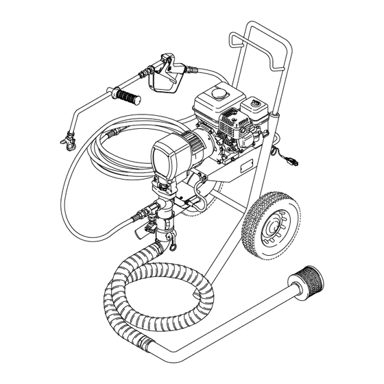
- Page 1 INSTRUCTIONS-PARTS LIST This manual contains important warnings and information. READ AND KEEP FOR REFERENCE. INSTRUCTIONS Roof Rigs GM 1230 GASOLINE-POWERED AIRLESS SPRAYER 1200 psi (8.3 MPa, 83 bar) MAXIMUM WORKING PRESSURE Model 231–148 With one gun, Heavy Duty RAC IV DripLess Tip Guard, and 861 size tip,...
-
Page 2: Table Of Contents
Warnings ........Setup . -
Page 3: Warnings
Warning Symbol WARNING This symbol alerts you to the possibility of serious injury or death if you do not follow the instructions. FIRE AND EXPLOSION HAZARD Improper grounding, poor ventilation, open flames or sparks can cause a hazardous condition and result in a fire or explosion and serious injury. - Page 4 EQUIPMENT MISUSE HAZARD Equipment misuse can cause the equipment to rupture or malfunction and result in serious injury. INSTRUCTIONS This equipment is for professional use only. Read all instruction manuals, tags, and labels before operating the equipment. Use the equipment only for its intended purpose. If you are not sure, call your Graco distributor. Do not alter or modify this equipment.
- Page 5 INJECTION HAZARD Spray from the gun, leaks or ruptured components can inject fluid into your body and cause extremely serious injury, including the need for amputation. Fluid splashed in the eyes or on the skin can also cause serious injury. Fluid injected into the skin may look like just a cut, but it is a serious injury.
- Page 6 Notes...
-
Page 7: Setup
TRIGGER LOCK SHOWN IN ENGAGED OR “SAFE” POSITION TRIGGER LOCK SHOWN IN DISENGAGED OR “OFF–SAFE” POSITION 40 ft (12 m) HOSE SPRAY GUN 40 ft (12 m) HOSE WAND HANDLE 50 ft. (15 m) MAIN HOSE 0398 PRESSURE CONTROL KNOB PRESSURE CONTROL ON/OFF SWITCH PRESSURE... - Page 8 General Information NOTE: Reference numbers and letters in parentheses in the text refer to the callouts in the figures and the parts drawing. WARNING FIRE AND EXPLOSION HAZARD Before operating the pump, ground the system as explained below. Also read the section FIRE OR EXPLOSION HAZ- ARD on page 3.
-
Page 9: Fueling
1. Read and follow the warnings on pages 3–3 before setting up or operating this sprayer. 2. Install the hoses and gun. 3. Clamp the siphon hose to the pump. Be sure the gasket is in the quick disconnect elbow; air leaks will prevent priming. -
Page 10: Start Up
Before You Start The Sprayer See FLUSHING GUIDELINES, page 12, to deter- mine if the unit should be flushed. Be sure the gas tank is full. Check the engine oil level. NOTE: The engine stops automatically, or will not start, if it is low on oil. - Page 11 6. To start the pump: a. Place a container under the pressure drain valve and open the valve. b. Reduce the engine speed by moving the metal throttle lever away from the fuel tank about half way to the left. c.
-
Page 12: Flushing Guidelines
Flushing Guidelines WARNING To reduce the risk of serious injury, including fluid injection, always follow the Pressure Relief Proce- dure Warning on page 8 before checking, adjust- ing, cleaning, or shutting down the sprayer. When To Flush 1. Flush a new sprayer to remove the protective oil. Before using water–base coating, flush with a com- patible solvent, then warm, soapy water, and then clean water. -
Page 13: Spray Tip And Tip Guard
Spray Tip and Tip Guard WARNING To reduce the risk of fluid injection or splashing in the eyes or on the skin, completely relieve the fluid pressure before installing, cleaning, or changing tips. See the Pressure Relief Procedure on page Installation 1. -
Page 14: Spray Techniques
Spray Techniques MOVE HORIZONTALLY AT A STEADY RATE Fig. 12 Type of Coating Fibered? Recommended Primers Aluminum Solvent–Base Aluminum Emulsion Asphalt Solvent–Base Asphalt Emulsion Aluminum Solvent–Base Aluminum Emulsion Asphalt Emulsion Roof coatings vary greatly. The formulas, batch, temperature, and age of the coating all affect its vis- cosity. -
Page 15: Maintenance
WARNING To reduce the risk of serious injury, always follow the Pressure Relief Procedure on page 8 before checking, adjusting, cleaning, or shutting down the sprayer. CAUTION For detailed engine maintenance and specifications, refer to the HONDA engine manual. CAUTION Close the black fuel shutoff lever whenever you are transporting the sprayer to prevent fuel from flooding the engine. -
Page 16: Troubleshooting
WARNING To reduce the risk of serious injury whenever you are instructed to relieve pressure, always follow the Pressure Relief Procedure on page 8. PROBLEM CAUSE Engine/sprayer won’t start Engine switch not on Out of gas Engine oil level low Spark plug cable disconnected or spark plug damaged Adjusting the pressure control knob... - Page 17 PROBLEM CAUSE Engine starts but dies Oil level drops below oil sensor Displacement pump output low Siphon hose strainer is clogged on upstroke Piston ball check not seating Piston packings worn or damaged Sleeve o–ring in displacement pump worn or damaged Displacement pump output low Siphon hose strainer is clogged on downstroke or both strokes...
-
Page 18: Removing And Installing A Displacement Pump
Removing and Installing a Displacement Pump Removal WARNING To reduce the risk of serious injury, always follow the Pressure Relief Procedure on page 8 before repairing the sprayer. 1. Flush the sprayer. Remove the suction hose, if used. WARNING To reduce the risk of pinching or amputating a finger, keep your fingers away from the area of the connection rod and pin while jogging the engine. -
Page 19: Displacement Pump
Removing and Installing A Displacement Pump 4. Check the back of the bearing housing to be sure the parts are installed properly. 5. Lift the pump to align the mounting holes and install the mounting screws. IMPORTANT – torque the screws to 20 ft-lb (27 N.m). - Page 20 Displacement Pump Repair Kit A Packing Repair Kit, Part No. 224–523, is available. Use all the parts in the kit for the best results. Parts included in the kit are marked with an asterisk in the text and drawings. For example, 408*. Reassemble the pump NOTE: Refer to Fig.
-
Page 21: Poly
Displacement Pump POLY LIPS OF V–PACKINGS MUST FACE DOWN LEATHER LIPS OF V–PACKINGS MUST FACE UP U–CUP SEAL LIPS MUST FACE DOWN Fig. 17 LEATHER LIPS OF V–PACKINGS MUST FACE DOWN TORQUE ROD (1) TO HOUSING (16) TO 34–50 FT–LB (44–68 N.m) TORQUE NUT (14) TO HOUSING (16) -
Page 22: Bearing Housing And Connecting Rod
Bearing Housing and Connecting Rod WARNING To reduce the risk of serious injury, always follow the Pressure Relief Procedure on page 8 before repairing the sprayer. NOTE: Steps 1 to 10 refer to Fig. 18. 1. Refer to Removing the pump on page 18. 2. -
Page 23: Drive Housing
WARNING To reduce the risk of serious injury, always follow the Pressure Relief Procedure on page 8 before repairing the sprayer. NOTE: Refer to Fig. 19 for this procedure. 1. Disconnect the suction hose (A). Disconnect the pressure control cord (62). Remove the front cover (21). -
Page 24: Pinion Housing
Pinion, Clutch, Clamp, Field, and Engine Disassembling these parts can start from the pinion housing or from the clutch, if no pinion service is needed. If starting from the pinion housing , first follow Steps 1 to 6 of DRIVE HOUSING, on page 23, and then contin- ue with the procedure below. - Page 25 CUTAWAY VIEW OF PINION HOUSING (19a) BACK OF PINION HOUSING (19a) PRESS PINION ASSEMBLY IN HERE 0041 Lubricate exterior Fig. 21 Repairing the Pinion NOTE: Refer to Fig. 21 except where noted. NOTE: A hydraulic press is required if you purchase the pinion parts individually.Otherwise, use Repair Kit No.
-
Page 26: Clutch
NOTE: The clutch assembly (9) includes the armature (9b) and rotor (9a). The armature and rotor must be replaced together so they wear evenly. NOTE: If the pinion assembly (19) is not yet separated from the clutch housing, follow Steps 1 to 4. Otherwise, start at Step 5. -
Page 27: Engine
Working under the mounting plate (A) of the cart, re- move the screw (5), lockwasher (6) and washer (7). See Fig. 24. Remove the engine-mounting locknuts (43) and screws (42). Disconnect the mating black, white and green wires. Pull the wires carefully through the grommets (8) before removing the engine. -
Page 28: Field And Wiring Harness
Field and Wiring Harness NOTE: Refer to Fig. 26. Remove the engine. See page 27. Loosen the setscrews (16). Unplug the wiring har- ness (69) from under the engine mounting plate. Pull the field out to expose the black and white wires. Fig. -
Page 29: Clamp
NOTE: A standard steering wheel puller and two1/4–28 x 3 or 4 in. long screws are required to remove the clamp. NOTE: Refer to Fig. 27. Loosen the two screws (4) on the clamp (15), work- ing through the slot at the bottom of the clutch hous- ing (17). -
Page 30: Reassembly
1. Install the clutch housing (17), capscrews (11) and lockwashers (12) on the engine. See Fig. 29. 2. Install the engine shaft key (14). See Fig. 29. 3. Install the clamp (15) onto the engine shaft (A). Maintain the 1.99 in. +/– 0.01 (50.54 mm) dimension shown in Fig. - Page 31 NOTE: Refer to Fig. 31 for Steps 5–9. 5. Place the engine (45) on the cart. Align the mount- ing holes. Guide the engine wire (A) and wiring har- ness (69) through the mounting plate grommets (8). Install the screws (42) and nuts (43) and torque to 15 ft–lb (20 N.m).
-
Page 32: Parts - Displacement Pump
Parts – Displacement Pump Model 224–527, Series A Includes items 401–423 Part No. Description 187–067 ROD, piston 187–071* V–PACKING, poly 187–069* GLAND, male, steel 111–486* O–RING 187–066 CYLINDER 187–074* GLAND, male 187–072* V–PACKING, poly 187–102* U–CUP SEAL 187–064 GUIDE, ball 224–407 HOUSING, pump intake 102–973*... -
Page 33: Pinion Assembly
Parts – Pinion Assembly Ref No. 19 Pinion Housing Includes items 19a to 19f PART NO. DESCRIPTION 221–032 PINION SHAFT ASSEMBLY Includes items 19b to 19f 183–395 .SHAFT, pinion 108–797 .BEARING, ball 108–798 .BEARING, ball 108–796 .RING, retaining, external 183–396 .HUB, armature Lubricate exterior... -
Page 34: Complete Sprayer
Parts – Complete Sprayer COMPLETE SPRAYER Model 231–148 Includes items 101 to 104 Part No. Description 224–439 HOSE, coupled 3/4 npt(m) x 3/4 nspm(f) swivel, 3/4” ID, 50 ft (15 m) long 224–472 MASTIC FLOW VALVE See manual 308–124 for parts 224–440 HOSE, coupled 3/4 npt x 1/2 npt (mbe), 5/8”... -
Page 35: Suction Kit
Parts – Suction Kit and Roofing Pump SUCTION KIT Model 224–442 Includes items 301 to 306 Part No. Description 111–338 COUPLER, 90 quick disconnect 187–123 HOSE, 2” ID 187–131 SUCTION TUBE 187–119 STRAINER CLAMP (clamp supplied with sprayer – requires special tool; use radiator clamp as alternative) 111–340 GASKET... - Page 36 DANGER LABEL ID LABEL WARNING LABEL SEE PARTS ON PAGE 33 Parts – Drive ID LABEL Ref 37 SEE PARTS ON PAGE 33 Ref 34 WARNING LABEL DETAIL ABOVE 0397A...
-
Page 37: Drive Assembly
SPRAYER DRIVE ASSEMBLY Model 224–482, Series A Includes items 1 to 69 NO. PART NO. DESCRIPTION 220–919 GEAR REDUCER 105–510 LOCKWASHER, 1/4” 100–644 CAPSCREW, hex sch; 1/4–20 x 3/4” 108–803 CAPSCREW, hex sch; 1/4–28 x 1” 100–469 CAPSCREW, hex hd; 3/8–16 x 3/4”... -
Page 38: Accessories
USE ONL Y DANGER LABELS The English language DANGER label shown on page 1 is also on your sprayer. If you have painters who do not read English, order one of the following labels to apply to your sprayer. The drawing below shows the best placement of these labels for good visibility. -
Page 39: Technical Data
Engine ..... . 5 Horsepower, Honda Maximum Working Pressure ....Cycles/Gallon (liter) . -
Page 40: Warranty
Graco Standard Warranty Graco warrants all equipment manufactured by Graco and bearing its name to be free from defects in material and workmanship on the date of sale by an authorized Graco distributor to the original purchaser for use. With the exception of any special, extended, or limited warranty published by Graco, Graco will, for a period of twelve months from the date of sale, repair or replace any part of the equipment determined by Graco to be defective.
Need help?
Do you have a question about the Roof Rigs 224483 and is the answer not in the manual?
Questions and answers