Table of Contents
Advertisement
Instructions - - Parts List
GH Series Roof Rigs
Gas- -Hydraulic Airless Sprayers
Important Safety Instructions
Read all warnings and instructions in this manual.
Save these instructions.
GH5030
Model 687100, Series C
4900 psi (33.8 MPa, 337 bar)
Maximum Working Pressure
GH3640
Model 687327, Series D
3600 psi (24.5 MPa, 245 bar)
Maximum Working Pressure
GH2560
Model 965168, Series B
2400 psi (16.6 MPa, 166 bar)
Maximum Working Pressure
GH2075
Model 965171, Series B
1800 psi (12.4 MPa, 124 bar)
Maximum Working Pressure
GH1015
Model 965165, Series C
1000 psi (0.70 MPa, 70 bar)
Maximum Working Pressure
GRACO INC. P.O. BOX 1441 MINNEAPOLIS, MN 55440- -1441
Copyright 1999, Graco Inc. is registered to I.S. EN ISO 9001
308972R
9089c
Advertisement
Table of Contents

Related Manuals for Graco 308972R


Summary of Contents for Graco 308972R
- Page 1 1800 psi (12.4 MPa, 124 bar) Maximum Working Pressure GH1015 Model 965165, Series C 1000 psi (0.70 MPa, 70 bar) Maximum Working Pressure GRACO INC. P.O. BOX 1441 MINNEAPOLIS, MN 55440- -1441 Copyright 1999, Graco Inc. is registered to I.S. EN ISO 9001 308972R 9089c...
-
Page 2: Table Of Contents
Warnings ........Component Identification . - Page 3 SKIN INJECTION HAZARD Spray from the gun, leaks or ruptured components can inject fluid into your body and cause extremely serious injury, including the need for amputation. Fluid splashed in the eyes or on the skin can also cause serious injury. D Fluid injected into the skin may look like just a cut, but it is a serious injury.
-
Page 4: Fire And Explosion Hazard
FIRE AND EXPLOSION HAZARD Improper grounding, poor ventilation, open flames or sparks can cause a hazardous condition and result in a fire or explosion and serious injury. D If there is any static sparking or you feel an electric shock while using this equipment, stop spray- ing immediately. -
Page 5: Component Identification
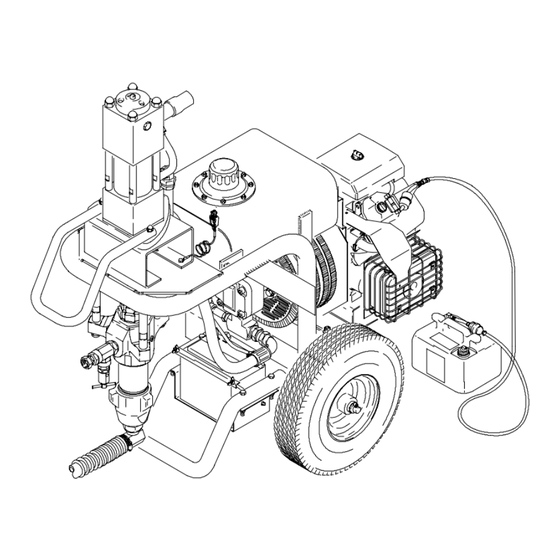
HYDRAULIC RETURN LINE TO MOTOR MOTOR RESET BUTTON HYDRAULIC MOTOR SUCTION TUBE CHECK VALVE PRESSURE DRAIN VALVE DISPLACEMENT PUMP SUCTION HOSE Fig 1 1. Connect the Hose and Gun a. Remove the plastic cap plug from the outlet tee and screw an accessory, conductive or grounded spray hose onto the 1/4 npsm(f) out- let nipple. -
Page 6: Oil Dipstick
3. Check the Hydraulic Oil Level a. Unscrew the hydraulic oil fill cap. See Fig 2. The dipstick is attached to the cap. The oil should be up to the full line on the dipstick. CAUTION To prevent damage to the cooling system and hydraulic pump, use only Graco Hydraulic Fluid, 169236 (5 gal./20 liter) or 207428 (1 gal/3.8 liter). - Page 7 5. Fill the Fuel Tank WARNING FIRE AND EXPLOSION HAZARD Fuel spilled on a hot surface can cause a fire or explosion and serious bodily injury and property damage. Shut off engine and let it cool before filling the tank. Carefully follow steps 5.a. to 5.c., below, being sure not to spill any fuel.
-
Page 8: Flushing
When to Flush 1. New sprayer. Your new sprayer was factory tested with lightweight oil which was left in to protect pump parts from corrosion. Before using oil- base paint, flush with mineral spirits only. Before using water- base paint, flush with mineral spirits, followed by soapy water, then a clean water rinse. - Page 9 WARNING FIRE AND EXPLOSION HAZARD To reduce the risk of static sparking and splashing when flushing, always remove the spray tip from the gun and hold a metal part of the gun firmly to the side of a grounded metal pail. 11.
-
Page 10: Operation
Pressure Relief Procedure WARNING SKIN INJECTION HAZARD The system pressure must be manually relieved to prevent the system from starting or spraying accidentally. Fluid under high pressure can be injected through the skin and cause serious injury. To reduce the risk of an injury from injection, splashing fluid, or moving parts, follow the Pressure Relief Procedure whenever you:... - Page 11 If the motor stalls during operation, turn OFF the igni- tion key. With your hand, firmly press straight down on the motor reset button. Now try to restart the sprayer. If it will not start, refer to the separate motor manual, 307158.
-
Page 12: Maintenance
1. Always stop the pump at the bottom of its stroke when you take a break and at the end of the day. This helps keep fluid from drying on the rod and damaging the packings. 2. Keep the displacement pump packing nut/wet cup 1/3 full of TSL at all times. -
Page 13: Troubleshooting
WARNING SKIN INJECTION HAZARD To reduce the risk of serious injury, whenever you are instructed to relieve pressure, follow the Pressure Relief Procedure on page 10. Check everything in the troubleshooting chart before disassembling the sprayer. PROBLEM Gas engine doesn’t work properly. Gas engine will not start. - Page 14 Replacing the Hydraulic Pump 1. Follow the Pressure Relief Procedure Warning on page 10. Let the hydraulic system cool before beginning the service procedure. 2. Unscrew the reservoir drain plug (51, page 36), having a container ready to catch the draining fluid.
-
Page 15: Top View
Replacing the Cooler and Blower 1. Follow the Pressure Relief Procedure Warning on page 10. Let the hydraulic system cool before beginning the service procedure. 2. Remove the hydraulic pump as instructed in the previous section. 3. Disconnect the cooler to reservoir return hose (7.) by loosening the hose clamp (8). -
Page 16: Displacement Pump Service
210208 Displacement Pump Disconnect the Displacement Pump 1. Flush the pump if possible. Stop the pump on the down stroke. 2. Follow the Pressure Relief Procedure Warning on page 10. 3. Reference Roof Rig Parts Drawings, page 30. 4. Remove the suction tube and fluid hose from the displacement pump. - Page 17 237510 and 222801 Displacement Pumps Disconnecting the Displacement Pump 1. Flush the pump, if possible. Stop the pump at the bottom of its stroke. WARNING To reduce the risk of serious injury whenever you are instructed to relieve pressure, always follow the Pressure Relief Procedure on page 10.
-
Page 18: Sprayer Parts Drawing
Model 687100 308972 Ref 29 9086B... - Page 19 NO. PART NO. DESCRIPTION 107074 BREATHER, fill cap 106114 STRAINER, inlet 107053 ELBOW, pipe, 90_, 1/2 x 3/8 npt 107128 TEE, service 107050 INSERT, hose, 1/2 npt(f) 178859 HOSE, rubber, 5 in. (125 mm) 102473 CLAMP, hose 210658 VALVE, ball 3/8 npt(m) 165472 ELBOW, pipe, 90_, 3/8 npt(f) 106039...
- Page 20 NO. PART NO. DESCRIPTION 107139 BOLT, carriage, 1/4 x 1 in. 100015 NUT, hex, 1/4--10 unc 178787 SHELF, battery 217286 CHECK VALVE, 1 in. npt (fbe) 196845 LABEL, ID, top 180233Y LABEL, warning 156172 UNION 206994 TSL, 8 oz. not shown 185016 LABEL, Caution 100004...
- Page 21 Model 687327 Ref 29 308972 9086B...
- Page 22 NO. PART NO. DESCRIPTION 107074 BREATHER, fill cap 106114 STRAINER, inlet 107053 ELBOW, pipe, 90_, 1/2 x 3/8 npt 107128 TEE, service 107050 INSERT, hose, 1/2 npt(f) 178859 HOSE, rubber, 5 in. (125 mm) 102473 CLAMP, hose 210658 VALVE, ball 3/8 npt(m) 165472 ELBOW, pipe, 90_, 3/8 npt(f) 106039...
- Page 23 NO. PART NO. DESCRIPTION 100011 WING NUT, 1/2 in. 107139 BOLT, carriage, 1/4 x 1 in. 100015 NUT, hex, 1/4--10 unc 178787 SHELF, battery 217286 CHECK VALVE, 1 in. npt (fbe) 196845 LABEL, ID, top 180233Y LABEL, warning 156172 UNION 206994 TSL, 8 oz.
- Page 24 Model 965168 308972 Ref 29 9087B...
- Page 25 NO. PART NO. DESCRIPTION 107074 BREATHER, fill cap 106114 STRAINER, inlet 107053 ELBOW, pipe, 90_, 1/2 x 3/8 npt 107128 TEE, service 107050 INSERT, hose, 1/2 npt(f) 178859 HOSE, rubber, 5 in. (125 mm) 102473 CLAMP, hose 210658 VALVE, ball 3/8 npt(m) 165472 ELBOW, pipe, 90_, 3/8 npt(f) 106039...
- Page 26 NO. PART NO. DESCRIPTION 107139 BOLT, carriage, 1/4 x 1 in. 100015 NUT, hex, 1/4--10 unc 178787 SHELF, battery 217286 CHECK VALVE, 1 in. npt (fbe) 196845 LABEL, ID, top 196663 LABEL, ID 180233Y LABEL, warning 156172 UNION 206994 TSL, 8 oz. not shown 185016 LABEL, Caution 100004...
- Page 27 Model 965171 Ref 29 9087B 308972...
- Page 28 NO. PART NO. DESCRIPTION 107074 BREATHER, fill cap 106114 STRAINER, inlet 107053 ELBOW, pipe, 90_, 1/2 x 3/8 npt 107128 TEE, service 107050 INSERT, hose, 1/2 npt(f) 178859 HOSE, rubber, 5 in. (125 mm) 102473 CLAMP, hose 210658 VALVE, ball 3/8 npt(m) 165472 ELBOW, pipe, 90_, 3/8 npt(f) 106039...
- Page 29 NO. PART NO. DESCRIPTION 107139 BOLT, carriage, 1/4 x 1 in. 100015 NUT, hex, 1/4--10 unc 178787 SHELF, battery 217286 CHECK VALVE, 1 in. npt (fbe) 196845 LABEL, ID, top 196662 LABEL, ID 180233 LABEL, warning 156172 UNION 206994 TSL, 8 oz. not shown 185016 LABEL, Caution 100004...
- Page 30 Model 965165 308972 Ref 29 9088B 9088A...
- Page 31 NO. PART NO. DESCRIPTION 107074 BREATHER, fill cap 106114 STRAINER, inlet 107053 ELBOW, pipe, 90_, 1/2 x 3/8 npt 107128 TEE, service 107050 INSERT, hose, 1/2 npt(f) 178859 HOSE, rubber, 5 in. (125 mm) 102473 CLAMP, hose 210658 VALVE, ball 3/8 npt(m) 165472 ELBOW, pipe, 90_, 3/8 npt(f) 106039...
- Page 32 NO. PART NO. DESCRIPTION 100011 WING NUT, 1/2 in. 107139 BOLT, carriage, 1/4 x 1 in. 100015 NUT, hex, 1/4--10 unc 178787 SHELF, battery 217286 CHECK VALVE, 1 in. npt (fbe) 196845 LABEL, ID, top 180233 LABEL, warning 156172 UNION 206994 TSL, 8 oz.
- Page 33 LABEL LABEL Ref 58 To Starter To Engine Switch Models 687100, 687327, 965168, 965171, 965165 LABEL LABEL LABEL LABEL 7877c 308972 LABEL LABEL...
-
Page 34: Sprayer Parts List
NO. PART NO. DESCRIPTION 107074 BREATHER, fill cap 106114 STRAINER, inlet 107053 ELBOW, pipe, 90_, 1/2 x 3/8 npt 107128 TEE, service 107050 INSERT, hose, 1/2 npt(f) 178859 HOSE, rubber, 5 in. (125 mm) 102473 CLAMP, hose 210658 VALVE, ball 3/8 npt(m) 165472 ELBOW, pipe, 90_, 3/8 npt(f) 106039... - Page 35 NO. PART NO. DESCRIPTION 178788 COOLER 178861 178786 SUPPORT, pump 102169 CAPSCREW, hex hd, 5/16 x 1.5 100016 LOCKWASHER, spring, 1/4 in. 100011 WING NUT, 1/2 in. 107139 BOLT, carriage, 1/4 x 1 in. 100015 NUT, hex, 1/4--10 unc 178787 SHELF, battery 217286 CHECK VALVE, 1 in.
- Page 36 All Models Parts Drawing Models 687100, 687327, 965168, 965171, 965165 Ref 77 308972 Ref 22 7879b Ref 111 7879A...
-
Page 37: Accessories
Engine ....KOHLER Model CH.18 OH 4 cycle twin cylinder, air cooled, 18 HP, (13.4 Kw) Gasoline ....6.0 gallon (22.7 liter capacity) consumes 1.3 gal/hr (4.9 liter/hr) Hydraulic Fluid Sump... -
Page 38: Graco Warranty
Graco Warranty Graco warrants all equipment listed in this manual which is manufactured by Graco and bearing its name to be free from defects in material and workmanship on the date of sale to the original purchaser for use. With the exception of any special extended or limited warranty published by Graco, Graco will, for a period of twelve months from the date of sale, repair or replace any part of the equipment determined by Graco to be defective.
Need help?
Do you have a question about the 308972R and is the answer not in the manual?
Questions and answers