Sanyo KS0971 Technical & Service Manual
Dc inverter split system air conditioner
Hide thumbs
Also See for KS0971:
- Technical & service manual (108 pages) ,
- Instruction manual (50 pages) ,
- Submittal data (2 pages)
Table of Contents
Advertisement
TECHNICAL & SERVICE MANUAL
KS0971 + C0971
+ CL0971
KS1271 + C1271
+ CL1271
DC INVERTER SPLIT SYSTEM AIR CONDITIONER
Indoor Model No.
KS0971
KS1271
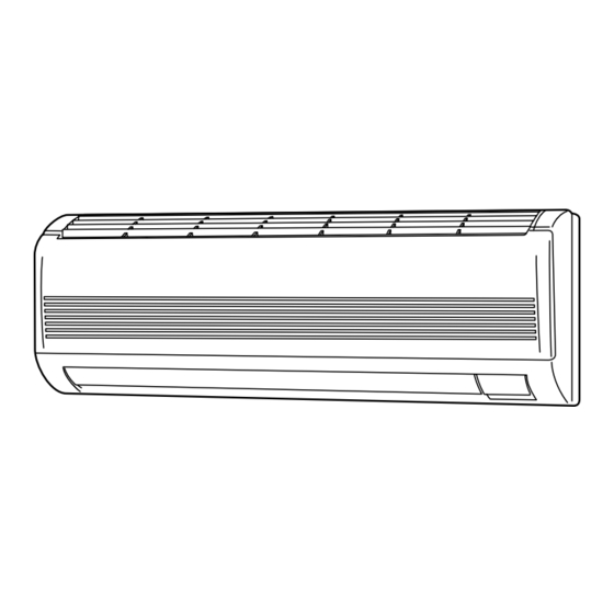
Indoor Unit
KS0971
KS1271
IMPORTANT
These air conditioners employ new
refrigerant R410A.
Pay special attention when
servicing the unit.
Product Code No.
1 852 099 81
1 852 099 82
FILE NO.
Outdoor Model No.
Product Code No.
C0971
1 852 330 23
C1271
1 852 330 24
CL0971
1 852 330 25
CL1271
1 852 330 26
Outdoor Unit
C0971
C1271
CL0971
CL1271
REFERENCE NO.
Destination: North America
SM
700655-01
Advertisement
Chapters
Table of Contents
Troubleshooting


Need help?
Do you have a question about the KS0971 and is the answer not in the manual?
Questions and answers
do you carry the plastic **** vent grill for this Sanyo CO971 Inverter controlled system air conditioner unit that is approx.16 years old.