
Related Manuals for Harman Kardon AVR 3550


Summary of Contents for Harman Kardon AVR 3550
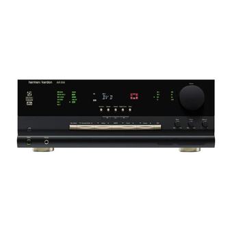
- Page 1 AVR 3550 Audio/Video Receiver OWNER’S MANUAL AVR 3550 AM/FM ® Power for the Digital Revolution ™...
-
Page 2: Table Of Contents
25 Operation Basic Operation Source Selection Controls and Use of Headphones Surround Mode Chart Carsten Olesen Surround Mode Selection Harman Kardon Europe A/S Digital Audio Playback Selecting a Digital Source 03/02 Digital Status Indicators Night Mode Tape Recording Output Level Trim Adjustment... -
Page 3: Introduction
With the purchase of a Harman Kardon which uses proprietary processing to create an traditional Harman Kardon high-current design AVR 3550 you are about to begin many years of open, spacious sound field even when only two technologies to meet the wide dynamic range of listening enjoyment. -
Page 4: Safety Information
Verify Line Voltage Before Use The carton and shipping materials used to potential for safety hazards, place the unit on Your AVR 3550 has been designed for use with protect your new receiver during shipment were a firm and level surface. When placing the 220-240-Volt AC current. -
Page 5: Front Panel Controls
Front Panel Controls AVR 3550 OPT12 COAX12 ANALOG TA AUTO TUNED ST HDCD PL II VMAx NF LOGIC 7 CM MULTI AM/FM Main Power Switch Input Source Selector Input Indicators System Power Control RDS Select Button Delay Power Indicator Test Tone Selector... - Page 6 Front Panel Controls Surround Mode Selector: Press this but- Surround Mode Indicators: A green LED Input indicators: A green LED will light in ton to change the surround mode by scrolling will light in front of the surround mode that is front of the input that is currently being used as through the list of available modes.
-
Page 7: Front Panel Information Display
Night Mode Indicator: This indicator for more information on preset stations.) When lights when the AVR 3550 is in the Night mode, Surround Modes are turned off and the unit will the Sleep function is in use, these numbers show play in pure stereo mode. - Page 8 Front Panel Information Display Preset Indicator: This indicator lights when the tuner is in use to show that the Preset Number/Sleep Timer is showing the sta- tion’s preset memory number. (See page 31 for more information on tuner presets). Sleep Indicator: This indicator lights when the Sleep function is in use.
-
Page 9: Rear Panel Connections
Rear Panel Connections ¶ ¢ ¡ · ‹ ‚ ° ™ • ¤ ∞ £ › fi § › ª fi › f ⁄ ‡ fl Tape Inputs Coaxial Digital Inputs Remote IR Input Tape Outputs Subwoofer Output Video 2 Video Inputs Video 1 Audio Inputs Video Monitor Outputs Remote IR Output... - Page 10 When remote controlled devices. Connect this jack to making speaker connections always make cer- the “IR IN” jack on Harman Kardon or other tain to maintain correct polarity by connecting compatible equipment. the red (+) terminals on the AVR to the red (+) Video 1 Video Inputs: Connect these jacks terminals on the speakers and the black (–) ter-...
-
Page 11: Remote Control Functions
Remote Control Functions Power On Button IR Transmitter Window Program/SPL Indicator Power Off Button Input Selectors AVR Selector AM/FM Tuner Select POWER EzSet Sensor Microphone Test Button Sleep Button Surround Mode Selector TAPE Night Mode CBL/SAT Channel Select Button VID 1 VID 2 Buttons 6 CH. - Page 12 AVR.) has been pressed. it is used to operate the AVR 3550. (See page 38 Sleep Button: Press this button to place When the AVR 3550 remote is being programmed...
- Page 13 TV/Video Button: This button does not button simply press the proper Numeric Keys When CD or DVD is selected using the Input have a direct function on the AVR 3550, but to select a station (See page 31 for more Selector button...
-
Page 14: Installation And Connections
S-Video sources should be connected the CD inputs fine, multistrand copper with an area greater to the AVR 3550 only with their S-Video In/ than 2 mm NOTE: When the CD player has both fixed and Outputs, not with their composite video connec- Cable with an area of 1.5 mm... -
Page 15: Scart A/V Connections
Note that with some adapter types it may be just capability) and turning the RGB video decoder of from the AVR 3550 to the TV if both, Video and turned around: If no signal is audible/ visible the TV on or off, depending on the DVD player´s S-Video sources, are used, and the appropriate when the VCR is playing connect the “Out”... -
Page 16: Remote Control Extension
Simply use this unit’s sensor or a remote eye by running a connection from the Remote IR Output jack to the Remote IR Input jack on Harman Kardon or other compatible equipment. AC Power Connections This unit is equipped with two accessory AC outlets. -
Page 17: Speaker Selection
Installation and Connections Speaker Selection Depending on the specifics of your room Center Front Speaker acoustics and the type of speakers in use, you No matter which type or brand of speakers is may find that imaging is improved by moving the No more than used, the same model or brand of speaker 60cm... -
Page 18: System Configuration
1. Plug the Power Cable into an un- Note that when the full OSD system is in use, The default settings for the AVR 3550, as it is switched AC outlet. the menu selections are not shown in the shipped from the factory, have all inputs set for Information Display . -
Page 19: Input Setup
Surround Setup Since the factory default for all inputs is Stereo, The first step in configuring the AVR 3550 is to Once the input setup has been completed, the the words S U R R O F F will initially appear in select an input. -
Page 20: Making Settings Independent Of Selected Input
System Configuration Making Settings independent of wish to make a change to the front speakers con- 6. Press the buttons on the remote selected Input figuration, press the buttons so that to select the option that best describes the sur- either LARGE or SMALL appears, matching round speakers in your system based on the After the settings described above have been... -
Page 21: Delay Settings
System Configuration the type of program source or surround mode As an example, in Figure 6 below, the left front b. When setting the delay time for the Dolby Pro you are listening to, press the buttons and right front speakers are set for “large, ” the Logic II mode, take the result of the calculation on the remote so that S W center, left surround and right surround speakers... -
Page 22: Night Mode Settings
SURR . When the button is pressed, the words AVR 3550’s output levels without the use of a DELAY line so that the delay for the sur- D-R (Dynamic Range) followed by the current sound pressure meter, although manual adjust- round speakers may be set. -
Page 23: Manual Output Level Adjustment
System Configuration 8. During the adjustment you will see the loca- Manual Output Level Adjustment Continue to adjust the individual speakers until tion of the channel position being adjusted Output levels may also be adjusted manually, they all have the same volume. Note that adjust- appear in both the on-screen display (if connect- either to set them to a specific level with an SPL ments should be made with the... - Page 24 System Configuration When all channels have an equal volume level, Note: Output level adjustment is not available the adjustment is complete. Now turn the for the VMAx or Surround Off mode, as no sur- Volume down to about -40dB, other- round speakers are used (so level differences wise the listening level may be too high as soon between the speakers in the room cannot...
-
Page 25: Operation
Once you have completed the setup and configu- • Adjust the volume to a comfortable level using count down until the time has elapsed. ration of the AVR 3550, it is simple to operate the front panel Volume Control or remote When the programmed sleep time has elapsed, and enjoy. -
Page 26: Surround Mode Chart
Operation Surround Mode Chart MODE FEATURES DELAY TIME RANGE DOLBY DIGITAL Available only with digital input sources encoded with Dolby Digital data. It provides Center: 0 ms – 5 ms up to five separate main audio channels and a special dedicated Low Frequency Effects Initial Setting –... -
Page 27: Surround Mode Selection
Note that an optional, external RF demodulator Logic II Movie (with movies) or Music (with surround mode from the front panel, press the is required to use the AVR 3550 to listen to the music) surround mode or with the Harman Surround Mode Selector... -
Page 28: Selecting A Digital Source
PCM encoded DVDs. The digital circuits in Dolby Digital bitstream is being received. HDTV receivers, satellite systems or CD players to the AVR 3550 are capable of high quality digital- Depending on the audio track selected on the the Optical or Coaxial inputs on the rear... -
Page 29: Night Mode
NOTES: a standard play mode. appropriate audio track and thus language • The AVR 3550 can convert an analog input to a (”2.0” audio tracks can be played with all Pro 2. Although the AVR will decode virtually all DVD digital signal. -
Page 30: Output Level Trim Adjustment
The AVR 3550 is equipped for future expansion er you want to trim, the Program Indicator AVR 3550 is established using the test tone, as through the use of optional, external adapters for may change color to indicate the level. -
Page 31: Tuner Operation
Direct button , and then pressing Using the remote, up to 30 stations may be The AVR 3550’s tuner is capable of tuning AM, the Numeric Keys that correspond to the stored in the AVR 3550’s memory for easy recall FM and FM Stereo broadcast stations and receiv- station’s frequency. -
Page 32: Rds Operation
You may search for a specific Program Type you receive a partial message, or the RDS (PTY) by following these steps: The AVR 3550 is equipped with RDS (Radio Data Indicator going on and off, try slowly 1. Press the RDS button... -
Page 33: Advanced Features
Advanced Features The AVR 3550 is equipped with a number of The display brightness may also be changed by At the ADVANCED SELECT menu advanced features that add extra flexibility to pressing and holding the Set button on the make certain that the on-screen cursor is next the unit’s operation. -
Page 34: Semi Osd Settings
Both of those options are possible press the Buttons until the desired with the AVR 3550. time in seconds is displayed. Note that unlike To change the Full-OSD Time Out, you will need most of the other options in this menu, this is a... -
Page 35: Programming The Remote
4. When the button was not released in time programmed for all AVR 3550 functions, as well as listed in the setup code table booklet for that after the unit turned off, the proper code will be... -
Page 36: Programmed Device Function
52 is the Macro 2 button for the • Press the Sleep/Channel Up button flashing and stay amber. AVR 3550, but it is the “Favorite” button for complete the process and store the macro many cable television boxes and satellite 3. -
Page 37: Channel Control Punch-Through
Programming the Remote Channel Control Punch-Through Transport Control Punch-Through Resetting the Remote Memory The AVR’s remote may be programmed to oper- The AVR’s remote may be programmed to oper- As you add components to your home-theater ate so that the channel control function for either ate so that the Transport Control Functions system, occasionally you may wish to totally the TV, cable or satellite receiver used in your sys-... -
Page 38: Function List
Function List Button Name AVR Function CD/CDR Power On Power On Power On Power On Power Off Power Off Power Off Power Off Mute Mute AVR Select DVD Input Select DVD Select CD Input Select CD Select Tape Tape Input Select VID 1 Video 1 Select VID 2... - Page 39 Function List Button Name Tape VCR (VID 1) TV (VID 2) Power On Power On Power On Power On Power On Power On Power Off Power Off Power Off Power Off Power Off Power Off Mute Mute Tape Tape Select VID 1 VCR Select VID 2...
-
Page 40: Troubleshooting Guide
Digital Audio stops • Check that Digital Signal is fed to the Digital Input selected Processor Reset To clear the AVR 3550’s entire system memory NOTE: Resetting the processor will erase any including tuner presets, output level settings, configuration settings you have made for speak-... -
Page 41: Technical Specifications
Height measurement includes feet and chassis. All features and specifications are subject to change without notice. Harman Kardon is a registered trademark, and Power for the digital revolution is a trademark, of Harman International Industries, Inc. is a trademark of Harman International Industries, Inc. - Page 42 250 Crossways Park Drive, Woodbury, New York 11797 www.harmankardon.com Harman Consumer International: 2, route de Tours, 72500 Château-du-Loir, France © 2002 Harman Kardon, Incorporated Part No.: cqx1a777z...