Harman Kardon AVR354 Service Manual
7 x 75w 7.1 channel a/v receiver
Hide thumbs
Also See for AVR354:
- Service manual (60 pages) ,
- Quick start manual (2 pages) ,
- Owner's manual (76 pages)
Table of Contents
Advertisement
harman/kardon
7 X 75W 7.1 CHANNEL A/V RECEIVER
ESD WARNING.....................................2
LEAKAGE TESTING...............................3
BASIC SPECIFICATIONS.......................4
PACKAGING........................................5
FRONT PANEL CONTROLS.....................6
REAR PANEL CONNECTIONS................8
REMOTE CONTROL FUNCTIONS..........11
CONNECTIONS..................................14
OPERATION.......................................28
TROUBLESHOOTING GUIDE.................33
PROCESSOR RESET............................34
Released 2008
Discontinued XXXX
AVR354
SERVICE MANUAL
CONTENTS
250 Crossways Park Dr.
Woodbury, New York 11797
DISASSEMBLY....................................35
UNIT EXPLODED VIEW..........................36
EXPLODED VIEW PARTS LIST...............37
AMP BIAS ADJUSTMENT......................38
BLOCK DIAGRAM.................................39
ELECTRICAL PARTS LIST......................40
PCB DRAWINGS..................................87
SEMICONDUCTOR PINOUTS.................95
SCHEMATICS.....................................194
WIRING DIAGRAM.....................................208
Rev0
5/2008
Advertisement
Table of Contents

Related Manuals for Harman Kardon AVR354


Summary of Contents for Harman Kardon AVR354
-
Page 1: Table Of Contents
AVR354 7 X 75W 7.1 CHANNEL A/V RECEIVER SERVICE MANUAL CONTENTS ESD WARNING……………………………….2 DISASSEMBLY………………………………35 LEAKAGE TESTING……………….…..…..3 UNIT EXPLODED VIEW……………………..36 BASIC SPECIFICATIONS…………………..4 EXPLODED VIEW PARTS LIST……………37 PACKAGING………………………..………..5 AMP BIAS ADJUSTMENT………………….38 FRONT PANEL CONTROLS………..…..…..6 BLOCK DIAGRAM…………………….……..39 REAR PANEL CONNECTIONS………….…8 ELECTRICAL PARTS LIST….…….……..…40 REMOTE CONTROL FUNCTIONS.………11... -
Page 2: Esd Warning
AVR354 Some semiconductor (solid state) devices can be damaged easily by static electricity. Such components commonly are called Electrostatically Sensitive (ES) Devices. Examples of typical ES devices are integrated circuits and some field effect transistors and semiconductor "chip" components. -
Page 3: Leakage Testing
AVR354 SAFETY PRECAUTIONS The following check should be performed for the continued protection of the customer and service technician. LEAKAGE CURRENT CHECK Measure leakage current to a known earth ground (water pipe, conduit, etc.) by connecting a leakage current tester... -
Page 4: Basic Specifications
Unmeasurable Slew Rate 40V/µsec Harman Kardon and Logic 7 are trademarks of Harman International Industries, Incorporated, registered in the United States and/or other countries. EzSet/EQ, Designed to Entertain and The Bridge II logo are trademarks of Harman International Industries, Incorporated. -
Page 5: Packaging
AVR354 1. Instruction manual ass'y - Accessories 2. Package Drawing MICROPHONE ASS'Y MANUAL ASS'Y CARD WARRANTY POLY BAG BATTERY ASS'Y AM LOOP ANTENNA ASS'Y REMOCON ASS'Y SNOW PAD (L) SNOW PAD (R) FM 1 POLE ANT(UL) CORD,POEWR (UL) REMOCON ASS'Y(ZONE2) -
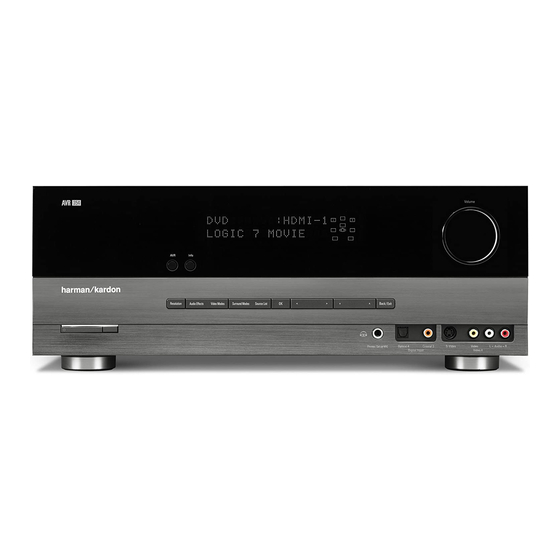
Page 6: Front Panel Controls
NOTE: If the PROTECT message ever appears, turn off the AVR the incoming signal. and unplug it. Check all speaker wires for a possible short. If none is found, bring the unit to an authorized Harman Kardon Navigation: These buttons are used to navigate the AVR’s menus service center for inspection and repair before using it again. - Page 7 AVR354 Info Message Display Speaker/Channel Remote Volume Input Indicators IR Sensor Headphone Jack/EzSet/EQ Power Resolution Video Source Navigation Digital Video 4 Analog Microphone Indicator List Audio Inputs Audio Inputs Modes Input (Optical 4 and Standby/On Main Power Audio Surround...
-
Page 8: Rear Panel Connections
AVR354 REAR-PANEL CONNECTIONS AM and FM Antenna Terminals: Input, while the Remote IR Output jack outputs a “stripped” signal that Connect the included AM has no carrier frequency. The full signal may be required by some and FM antennas to their respective terminals for radio reception. - Page 9 AVR354 S-Video Component Composite HDMI AC Power FM Antenna 1, 2 and 3 The Bridge II 1, 2 and 3 1, 2 and 3 1, 2 and 3 Input Video HDMI Monitor Component Video S-Video 2 Monitor AM Antenna...
- Page 10 After you have made all other connections, plug the The Bridge II Input: Connect the included Harman Kardon AC power cord into this receptacle and into an unswitched wall outlet. to this input for use with your iPod, iPod touch or iPhone (none of which are included).
-
Page 11: Remote Control Functions
AVR354 MAIN REMOTE CONTROL FUNCTIONS The AVR 354 remote is capable of controlling 7 devices, including the AVR Power On Button: Press this button to turn on the AVR. The AVR itself and an iPod or iPhone docked in the included The Bridge II. -
Page 12: Main Remote Control Functions
AVR354 MAIN REMOTE CONTROL FUNCTIONS Volume Control: Zone Selector: Press this button to raise or lower the volume. Use this switch to select whether AVR commands will affect the main listening area (Zone 1) or the remote zone of a... - Page 13 AVR354 IR Transmitter Lens AVR Power Off Device Power On AVR Power On Device Power Off Source Selectors Video Modes Audio Effects Surround Modes Alphanumeric Keys Activity Last Back/Exit Menu Navigation Disc Menu Light Teletext Volume Channel Mute Transport Controls...
-
Page 14: Connections
AVR354 CONNECTIONS There are different types of audio and video connections used to Bare wire cables are installed as follows (see Figure 2): connect the receiver to the speakers and video display, and to connect 1. Unscrew the terminal cap until the pass-through hole in the collar is the source devices to the receiver. -
Page 15: Audio Connections
AVR354 CONNECTIONS Audio Connections If your video display or source device is not HDMI-capable, use one of the analog video connections (composite, S- or component video) There are two formats for audio connections: digital and analog. Digital and, if available on your source device, either a coaxial or optical digital audio signals are required for listening to sources encoded with digital audio connection. -
Page 16: Video Connections
Figure 8 – Multichannel Analog Audio Figure 10 – Composite Video Harman Kardon receivers also include a proprietary, dedicated audio connection called The Bridge II. If you own an iPod with a dock con- S-video, or “separate” video, transmits the chrominance and luminance nector or an iPhone, connect The Bridge II (included) to The Bridge II components using separate wires contained within a single cable. - Page 17 AVR354 CONNECTIONS The FM antenna uses a 75-ohm F-connector. See Figure 13. Figure 13 – FM Antenna The AM loop antenna needs to be assembled. Connect the two leads to the spring terminals on the receiver. As AM antenna leads have no polarity, it doesn’t matter which of the two terminals is used for either...
- Page 18 AVR354 INSTALLATION You are now ready to connect the various components to the receiver. Before beginning, turn off all components, including the AVR 354, and unplug their power cords. Don’t plug in any of the power cords until you have finished making all of your connections.
-
Page 19: Hdmi Connections
AVR354 INSTALLATION The precise connections to be made depend on the capabilities of the If the player is capable of playing multichannel discs, including DVD- source device and your video display (TV). Select the best audio and Audio, SACD, Blu-ray Disc and HD-DVD, but it is not capable of video connections for each source. - Page 20 AVR354 INSTALLATION • Connect the DVD player’s S-video or composite video output (use one connection only) to the Video 1, 2 or 3 Input on the AVR. You may also use the Video 4 Composite or S-video Input located on the AVR’s front panel (see Figure 31).
- Page 21 HDMI connector, but they both have component video connectors, through the Harman Kardon Parts Dept. You may then connect connect the set-top box as follows (see Figure 25): it to any set of analog audio inputs.
- Page 22 The Bridge II that is included with the AVR 354 in connections are required from the AVR to the video display. Analog the future, contact Harman Kardon and make sure to order video sources (composite, S-video and component) are converted to The Bridge II as a replacement.
- Page 23 AVR354 INSTALLATION You may plug one device into the AC Switched Accessory Outlet on the rear of the AVR 354. See Figure 35. Make sure this device draws no more than 50 watts. The device should have its mechanical or master power switch turned on, and it will power on any time the AVR 354 is turned on.
- Page 24 If the device does not turn off, try entering another code. If you of DVD players, cable boxes, satellite receivers, the Harman Kardon run out of codes, you may search through all of the codes in the DMC 1000 digital media center and TVs.
- Page 25 IR receiver, such as the optional Harman Kardon HE 1000, to the Remote IR Input jack. When you are using the AVR 354 in multizone mode, you may connect an optional IR receiver, Figure 40 –...
- Page 26 AVR354 INSTALLATION IMPORTANT SAFETY NOTE: Installing a multizone system typi- If you prefer not to purchase an external amplifier, you may reassign cally requires running various cables inside walls. Always comply the AVR 354’s Surround Back amplifier channels to power the with the appropriate safety codes when installing concealed wiring.
- Page 27 AVR354 INSTALLATION b) Using the remote, press the AVR Power On Button or any of the Source Selectors. See Figure 46. Figure 46 – AVR Power On and Source Selectors NOTES: • Any time you press one of the Source Selectors on the remote (i.e., Cable/Sat, DVD, Media Server, Radio, TV, Game...
-
Page 28: Operation
If none is found, bring front panel, the display will return to full-brightness. The display will dim the unit to an authorized Harman Kardon service center for again several seconds after your last command. -
Page 29: Using The Tuner
AVR354 OPERATION The DOLBY H:BYPASS message indicates that Dolby Headphone Additional tips for systems using HDMI: surround processing is in the default bypass mode, which delivers • Turn off all devices (including the TV, AVR and any source a conventional 2-channel signal to the headphones. - Page 30 AVR354 OPERATION ‹ › To tune a preset station, press the Buttons or the Channel 2. Use the Buttons to scan through the channel numbers in ⁄ ¤ Control, or press the Menu Button to view the list of programmed pre- the default All Channel search mode.
-
Page 31: Using Docking Station
AVR354 OPERATION to navigate it. Visual materials will be displayed on a video NOTES: display connected to the AVR. 1. Analog audio signals are not converted to digital form, and digital audio signals are not converted to analog audio form. -
Page 32: Selecting A Surround Mode
AVR354 OPERATION In addition, if a video display is connected to the AVR 354, it will display information about the status of the iPod and the track, including the play mode icon, any art, the song title, artist and album. At the bottom of the screen is a graphic bar indicating the current play position within the track, with the elapsed and remaining times appearing below the bar. -
Page 33: Troubleshooting Guide
• Amplifier is in protection mode • Contact your local Harman Kardon service center due to internal problems No sound from surround or • Incorrect surround mode • Select a mode other than Stereo center speakers •... -
Page 34: Processor Reset
Follow the directions in the owner’s manual on page 34 to restore the picture if necessary. If the receiver still does not function correctly after a processor reset, contact an authorized Harman Kardon service center for assistance. Authorized service centers may be located by visiting our Web site at www.harmankardon.com. -
Page 35: Disassembly
DISASSEMBLY AVR354 1. Removing the Top Cabinet 3. Removing the Rear Panel Remove the Screws Remove the Screws 27 28 29 30 4. Removing the Main PCB Remove the Screws 2. Removing the Front Panel Remove the Screws... -
Page 36: Unit Exploded View
AVR354 EXPLODED VIEW 40-3 40-1 40-4 39-1 40-5 39-3 38-1 40-7 38-2 DESCRIPTION PARTS NO. Q,ty REMARK ORNAMENT , VOLUME CGU1A318Y 40-2 CAP , VOLUME CGX1A338MBC63 HOLDER , VOLUME CMH1A214 INDICATOR , VOLUME CGL1A222 WINDOW ASS'Y CGUAVR354 CGU3A399Z WINDOW , FIP... -
Page 37: Exploded View Parts List
AVR354... -
Page 38: Amp Bias Adjustment
AVR354 AMPLIFIER SECTION BIAS ADJUSTMENT Measurement condition .No input signal or volume position is minimum. Standard value .Ideal current = 48mA (± 5%) .Ideal DC Voltage = 25.92mV (± 5%) DC EVM CUP12026* (MAIN PCB) CN66 CN61 CN64 CN63... -
Page 39: Block Diagram
TX UNBAL TMP86F409NG COAX.2 DETECT iPod RX iPod CONT (8BIT u-COM for iPod) -VCC2 iPod CVBS iPod CVBS AVR354 & 355 OPTION FLI30336 COAX OUT ST232CDR TORINO AC OUTLET AC IN ADV7342 AVR354 & 355 OPTION CLKIN XMCK DIGITAL VIDEO... -
Page 40: Electrical Parts List
AVR354 AVR354 Electrical Parts List Ref. Designator Part Number Description FRONT PCB ASSY CUP12025 Capacitors C714 CCBS1H151KBT CAP , CERAMIC 150UF 50V K C716 CCEA1AH331T CAP , ELECT 330UF 10V C719 CCBS1H102KBT CAP , CERAMIC 1000PF 50V K C720... - Page 41 AVR354 Ref. Designator Part Number Description FRONT PCB ASSY CUP12025 C897 CCEA1AH471T CAP , ELECT 470UF 10V C903 CCEA1HKS2R2T CAP , ELECT 2.2UF 50V SMALL SIZE C905 CCEA1HKS2R2T CAP , ELECT 2.2UF 50V SMALL SIZE Semiconductors D455 CVD1SS133MT DIODE...
- Page 42 AVR354 Ref. Designator Part Number Description FRONT PCB ASSY CUP12025 R737 CRD20TJ100T RES , CARBON 10 OHM 1/5W J R747 CRD20TJ103T RES , CARBON 10K OHM 1/5W J R753 CRD20TF1001T RES , CARBON 1K /1/5W /F R754 CRD20TF1501T RES , CARBON 1.5K /1/5W /F...
- Page 43 AVR354 Ref. Designator Part Number Description FRONT PCB ASSY CUP12025 R915 CRD20TJ473T RES , CARBON 47K OHM 1/5W J R918 CRD20TJ472T RES , CARBON 4.7K OHM 1/5W J R919 CRD20TJ472T RES , CARBON 4.7K OHM 1/5W J R920 CRD20TJ102T...
- Page 44 AVR354 Ref. Designator Part Number Description FRONT PCB ASSY CUP12025 JW84 CWE8202110RV WIRE ASS'Y WIRE JW88 CWE8202150RV WIRE ASS'Y WIRE RL45 CSL4A016ZU RELAY , 12V 2C2P RELAY CSH1A008ZV SW , PUSH (MOMS) SWITCH VR74 CSR2A037Z ENCODER ENCODER CHG1A306 CUSHION...
- Page 45 AVR354 Ref. Designator Part Number Description MAIN PCB/HEATSINK (CUP12026) C803 CCCT1H330JC CAP , CERAMIC 33PF 50V J C804 CCCT1H330JC CAP , CERAMIC 33PF 50V J C805 CCCT1H120JC CAP , CERAMIC 12PF 50V J C806 CCCT1H120JC CAP , CERAMIC 12PF 50V J...
- Page 46 AVR354 Ref. Designator Part Number Description MAIN PCB/HEATSINK (CUP12026) C638 CCEA1JH221E CAP , ELECT 220UF 63V C639 CCEA1JH221E CAP , ELECT 220UF 63V C640 CCEA1JH221E CAP , ELECT 220UF 63V C807 CCEA1JH221E CAP , ELECT 220UF 63V C808 CCEA1JH221E...
- Page 47 AVR354 Ref. Designator Part Number Description MAIN PCB/HEATSINK (CUP12026) Q511 HVTKTC3200GRT TRANSISTOR NPN KTC3200GR Q512 HVTKTC3200GRT KTC3200GR TRANSISTOR NPN Q513 HVTKTC3200GRT TRANSISTOR NPN KTC3200GR Q514 HVTKTC3200GRT KTC3200GR TRANSISTOR NPN Q515 HVTKTC3200GRT TRANSISTOR NPN KTC3200GR Q516 HVTKTC3200GRT TRANSISTOR NPN KTC3200GR...
- Page 48 AVR354 Ref. Designator Part Number Description MAIN PCB/HEATSINK (CUP12026) Q939 HVTKRA107MT TRANSISTOR PNP KRA107M Q941 HVTKSC2785YT KSC2785Y TRANSISTOR NPN Q942 HVTKSC2785YT TRANSISTOR NPN KSC2785Y Q943 HVTKSC2785YT KSC2785Y TRANSISTOR NPN Q951 HVTKRC107MT TRANSISTOR NPN KRC107M Q952 HVTKRA107MT TRANSISTOR PNP KRA107M...
- Page 49 AVR354 Ref. Designator Part Number Description MAIN PCB/HEATSINK (CUP12026) R517 CRD20TJ152T RES , CARBON 1.5K OHM 1/5W J R518 CRD20TJ152T RES , CARBON 1.5K OHM 1/5W J R519 CRD20TJ152T RES , CARBON 1.5K OHM 1/5W J R520 CRD20TJ152T RES , CARBON 1.5K OHM 1/5W J...
- Page 50 AVR354 Ref. Designator Part Number Description MAIN PCB/HEATSINK (CUP12026) R593 CRD20TJ561T RES , CARBON 560 OHM 1/5W J R594 CRD20TJ561T RES , CARBON 560 OHM 1/5W J R595 CRD20TJ561T RES , CARBON 560 OHM 1/5W J R596 CRD20TJ561T RES , CARBON...
- Page 51 AVR354 Ref. Designator Part Number Description MAIN PCB/HEATSINK (CUP12026) R687 CRD20TJ103T RES , CARBON 10K OHM 1/5W J R688 CRD20TJ103T RES , CARBON 10K OHM 1/5W J R689 CRD20TJ103T RES , CARBON 10K OHM 1/5W J R690 CRD20TJ103T RES , CARBON...
- Page 52 AVR354 Ref. Designator Part Number Description MAIN PCB/HEATSINK (CUP12026) R840 CRD20TJ561T RES , CARBON 560 OHM 1/5W J R841 CRD20TJ561T RES , CARBON 560 OHM 1/5W J R842 CRD20TJ561T RES , CARBON 560 OHM 1/5W J R843 CRD20TJ561T RES , CARBON...
- Page 53 AVR354 Ref. Designator Part Number Description MAIN PCB/HEATSINK (CUP12026) R944 CRD25TJ223T RES , CARBON 22K OHM 1/4W J R945 CRD20TJ223T RES , CARBON 22K OHM 1/5W J R946 CRD25TJ223T RES , CARBON 22K OHM 1/4W J R947 CRD20TJ223T RES , CARBON...
- Page 54 AVR354 Ref. Designator Part Number Description MAIN PCB/HEATSINK (CUP12026) CMD1A417 BRACKET , PCB BRACKET CMD1A600 BRACKET , FAN BRACKET CMD2A615 BRACKET , FAN BRACKET CMY1A303 HEAT SINK HEAT SINK CMY2A249 HEAT SINK HEAT SINK CTB3+10JR SCREW SCREW CTB3+8JR SCREW...
- Page 55 AVR354 Ref. Designator Part Number Description PCB , POWER TRANS/DOWNLOAD/DIG IN/OUT CUP12101 C105 CCBS1E103ZFT CAP , CERAMIC 0.01UF 25V C106 CCFT1H104ZF CAP , SEMICONDUCTOR 0.1UF 50V Z C107 CCBS1E103ZFT CAP , CERAMIC 0.01UF 25V C108 CCBS1E103ZFT CAP , CERAMIC 0.01UF 25V...
- Page 56 AVR354 Ref. Designator Part Number Description PCB , POWER TRANS/DOWNLOAD/DIG IN/OUT CUP12101 D105 CVD1N4003ST DIODE , RECT 1N4003 D108 CVD1N4003ST DIODE , RECT 1N4003 D109 CVDZJ8.2BT DIODE , ZENER ZJ8.2B 1/2W D111 CVDZJ8.2BT DIODE , ZENER ZJ8.2B 1/2W D114...
- Page 57 AVR354 Ref. Designator Part Number Description PCB , POWER TRANS/DOWNLOAD/DIG IN/OUT CUP12101 R879 CRD20TJ331T RES , CARBON 330 OHM 1/5W J R880 CRD20TJ331T RES , CARBON 330 OHM 1/5W J R882 CRD20TJ122T RES , CARBON 1.2K OHM 1/5W J...
- Page 58 AVR354 Ref. Designator Part Number Description PCB , POWER TRANS/DOWNLOAD/DIG IN/OUT CUP12101 BN80 CWB2B903180EN WIRE ASS'Y WIRE BN96 CWB1C915180EN WIRE ASS'Y(15P, 2MM, 180MM) WIRE BN97 CWB1C907120EN WIRE ASS'Y(7P, 2MM, 120MM) WIRE CN13 CJP05GA01ZY WAFER(YMW025-05R) WIRE CN19 CJP03GA90ZY WAFER WAFER...
- Page 59 AVR354 Ref. Designator Part Number Description PCB , INPUT CUP12028 C222 CCUS1H221JA CAP , CHIP 220PF 50V J C223 CCUS1H221JA CAP , CHIP 220PF 50V J C224 CCUS1H221JA CAP , CHIP 220PF 50V J C225 CCUS1H221JA CAP , CHIP...
- Page 60 AVR354 Ref. Designator Part Number Description PCB , INPUT CUP12028 C353 CCUS1H102KC CAP , CHIP 1000PF 50V K C354 CCUS1H102KC CAP , CHIP 1000PF 50V K C355 CCUS1H102KC CAP , CHIP 1000PF 50V K C356 CCUS1H102KC CAP , CHIP...
Need help?
Do you have a question about the AVR354 and is the answer not in the manual?
Questions and answers