
Subscribe to Our Youtube Channel
Related Manuals for Frigidaire PL36WC50EC


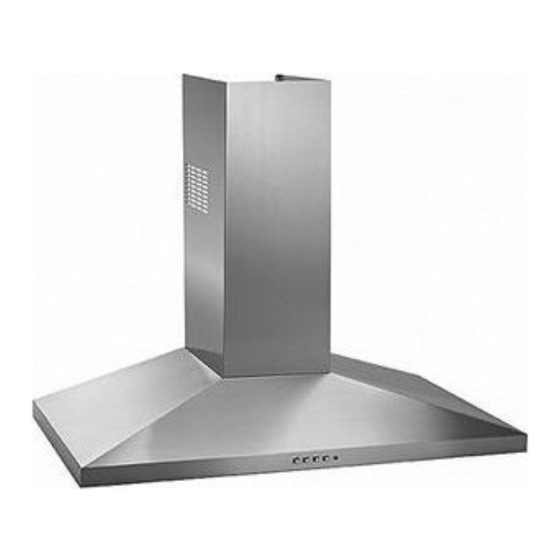
Summary of Contents for Frigidaire PL36WC50EC
- Page 1 PL36WC50EC Model ENGLISH........3 FRANÇAIS........12 99043841A...
-
Page 3: To Reduce The Risk Of Fire, Electric Shock, Or Injury To Persons, Observe The Following
READ AND SAVE THESE INSTRUCTIONS INTENDED FOR DOMESTIC COOKING ONLY WARNING TO REDUCE THE RISK OF FIRE, ELECTRIC SHOCK, OR INJURY TO PERSONS, OBSERVE THE FOLLOWING: 1. Use this unit only in the manner intended by the manufacturer. If you have questions, contact the manufacturer at the address or telephone number listed in the warranty. -
Page 4: Operation
OPERATION BLOWER Controls LIGHT PILOT MEDIUM SWITCH LAMP SPEED The hood is operated using the (4) push-buttons located at eye-level, on the front edge of the hood. BLOWER BLOWER ON-LOW / The light switch turns the halogen lamps on and off. HIGH SPEED The blower on-low / off switch turns the blower on to its lowest running speed. -
Page 5: Prepare The Hood
PREPARE THE HOOD Unpack hood and check contents. You should receive: 1 - Hood 1 - Decorative Flue Assembly 1 - Parts Bag containing: 1 - Mounting Bracket DISCHARGE MOUNTING 1 - Discharge Collar COLLAR BRACKET 1 - Flue Mounting Bracket 8 - Mounting Screws (4.8 x 38mm Pan Head) 4 - Mounting Screws (3.9 x 9.5mm Pan Head) 2 - Mounting Screws (3.9 x 6mm Flat Head) -
Page 6: Install The Ductwork
INSTALL THE DUCTWORK (DUCTED HOODS ONLY) ROOF CAP 6” CAUTION: To reduce the risk of fire, use only metal ductwork. ROUND DUCT 1. Decide where the ductwork will run between the hood and the outside. DECORATIVE WALL 2. A straight, short duct run will allow the hood to perform most efficiently. FLUE HOOD 3. -
Page 7: Install Flue Mounting Bracket
INSTALL FLUE MOUNTING BRACKET (DUCTED AND NON-DUCTED HOODS) 1. Assemble the flue mounting bracket, adjusting outside width as shown. See Figure 7. 2. Carefully center the mounting bracket directly over the range hood location. 3. Secure the bracket assembly to the ceiling using (2) 4.8x38mm mounting screws and drywall anchors (Fig. 8). Make sure the bracket is pushed into the corner, tight against the wall and centered over the hood. -
Page 8: Install The Hood
PREPARE THE HOOD (NON - DUCTED HOODS ONLY) Note: The following materials must be purchased separately for non-ducted recirculation installations. Non - Ducted Recirculation Kit, Model DFKTWC50EC. 5” diameter metal duct. 1. Discard discharge collar supplied with the hood. Install the 5” to 6” adapter supplied with the Non-Ducted Recirculation Kit. -
Page 9: Make Electrical Connections
MAKE ELECTRICAL CONNECTIONS WARNING: Electrical wiring must be done by a qualified person(s) in accor- WIRING BOX dance with all applicable codes and standards. This range hood must be COVER properly grounded. Turn off electrical power at service entrance before wir- ing. -
Page 10: Install Filters
INSTALL FILTERS (DUCTED AND NON-DUCTED HOODS) 1. To remove the GREASE filter, push in on the metal latch tab and tilt filter downward to remove. 2. To install the GREASE filter, align rear filter tabs with slots in the hood. Depress the metal latch tab, push filter into position and release. - Page 11 Service under this warranty must be obtained by contacting Electrolux at the addresses or phone numbers below. This warranty only applies in the USA and Canada. In the USA, your appliance is warranted by Electrolux Major Appliances North America, a division of Electrolux Home Products, Inc. In Canada, your appliance is warranted by Electrolux Canada Corp.
- Page 12 LISEZ ET CONSERVEZ CES INSTRUCTIONS SEULEMENT POUR UTILISATION DOMESTIQUE AVERTISSEMENTS POUR REDUIRE LES RISQUES D’INCENDIE, DE DECHARGES ELECTRIQUES OU DE DOMMAGES AUX PERSONNES, OBSERVEZ LES INSTRUCTIONS SUIVANTES: 1. N’utilisez cet appareil que comme cela est indiqué par le constructeur. Si vous avez des problèmes, contactez le fabriquant à l’adresse ou au numéro de téléphone indiqués dans la garantie.
-
Page 13: Entretien
FONCTIONNEMENT VOYANT LUMINEUX Commandes VENTILATEUR BOUTON VITESSE Votre hotte fonctionne grâce à (4) boutons sur lesquels vous devez appuyer et qui LUMIÈRE MOYENNE se trouvent à la hauteur de vos yeux, sur le bord antérieur de votre hotte. Le bouton de la lumière allume et éteint les ampoules halogènes. Le bouton du ventilateur ON-bas/OFF fait fonctionner le ventilateur à... - Page 14 PREPAREZ LA HOTTE Enlever la hotte dans l’emballage et controller le contenu. Vous devez recevoir : 1 - Hotte 1 - Conduit décoratif 1 - Sachet avec: 1 - Support de fixation SUPPORT COLLIER DE FIXATION D’EVACUATION 1 - Collier d’évacuation 1 - Étrier de support 8 - Vis d’assemblage (4.8 x 38mm Tête ronde) 4 - Vis d’assemblage (3.9 x 9.5mm Tête ronde)
-
Page 15: Installation Du Systeme D'evacuation
INSTALLATION DU SYSTEME D’EVACUATION COUVERCLE DU (UNIQUEMENT POUR LES HOTTES CARÉNÉES) TOIT TUYAU ROND ATTENTION: Pour réduire les risques d’incendie, n’utilisez que des tuyaux DE 6” (15cm) en métal. 1. Décidez où le tuyau rond doit être installé, entre votre hotte et l’extérieur. 2. -
Page 16: Préparation De La Hotte
INSTALLATION ETRIER DE SUPPORT (HOTTES CARÉNÉES OU NON CARÉNÉES) 1. Assemblez l’étrier de support du conduit décoratif en réglant la largeur extérieure comme indiqué. Fig. 7. 2. Centrez soigneusement l’étrier de support directement sur l’emplacement destine à la hotte. 3. Fixez l’etrier de support au plafond au moyen de deux (2) vis de montage de 4,8 x 38 mm et chevilles (Fig. 8). Vérifiez que le support est enfoncé... -
Page 17: Installation De La Hotte
PRÉPARATION DE LA HOTTE (CONFIGURATION NON CARÉNÉE) Remarque : Le matériel doit être acheté séparément pour des installations non carénées. Kit de recirculation non caréné, modèle DFKTWC50EC. Conduit en métal de 5" de diamètre. Ne comptez pas le collier d’évacuation fourni avec la hotte. Installez l’adaptateur de 5" à 6" fourni avec le kit de recirculation non caréné. - Page 18 FAITES LE RACCORDEMENT ELECTRIQUE BOITE DE ATTENTION : Les fils électriques doivent être installés par une/des CONNEXION personne(s) qualifiée(s) conformément à tous les codes et standards ELECTRIQUE applicables. Cette hotte doit être correctement mise à la terre. Éteignez l’alimentation électrique à l’entrée du branchement avant la connexion. 1.
-
Page 19: Installation Des Filtres
INSTALLATION DES FILTRES (CONFIGURATIONS CARÉNÉES ET NON CARÉNÉES) 1. Pour retirer le filtre à GRAISSE, attrapez la languette du taquet et abaissez-la afin de dégager le filtre de la hotte. 2. Pour remettre le filtre à GRAISSE en place, alignez les languettes arrière du filtre avec les fentes de la hotte. - Page 20 Cette garantie n’est valide qu’aux États-Unis et au Canada. Aux États-Unis, votre appareil est garanti par Electrolux Major Appliances North America, une division de Electrolux Home Products, Inc. Au Canada, votre appareil est garanti par Electrolux Canada Corp.
-
Page 21: Service Parts
SERVICE PARTS - LISTE PIECES DE RECHANGE MODELS PL36WC50EC KEY No. DESCRIPTION (ENGLISH ) DESCRIPTION (FRANCAIS) Grease Filter Filtre à graisse Motor Capacitor Condensateur Wiring Plate Plaque du système electrique Lamp Bulb Ampoule Blower Convoyer Motor Moteur Blower Wheel Turbine... - Page 22 SERVICE PARTS - LISTE PIECES DE RECHANGE MODEL PL36WC50EC - 22 -...
- Page 24 04307535...
Need help?
Do you have a question about the PL36WC50EC and is the answer not in the manual?
Questions and answers