Table of Contents
Advertisement
www.proform.com
Model No. PFEX05010.1
Serial No.
USER’'S MANUAL
Write the serial number in the space
above for reference.
Serial Number
Decal
QUESTIONS?
If you have questions, or if parts
are damaged or missing, DO NOT
CONTACT THE STORE; please
contact Customer Care.
IMPORTANT: Please register this
product (see the limited warranty
on the back cover of this manual)
before contacting Customer Care.
CALL TOLL-FREE:
1-888-533-1333
Mon.––Fri., 6 a.m.––6 p.m. MT
Sat. 8 a.m.––4 p.m. MT
ON THE WEB:
www.proformservice.com
CAUTION
Read all precautions and instruc-
tions in this manual before using
this equipment. Keep this manual
for future reference.
Advertisement
Table of Contents

Related Manuals for ProForm 590 Spx Bike


Summary of Contents for ProForm 590 Spx Bike
- Page 1 Model No. PFEX05010.1 Serial No. USER’’S MANUAL Write the serial number in the space above for reference. Serial Number Decal QUESTIONS? If you have questions, or if parts are damaged or missing, DO NOT CONTACT THE STORE; please contact Customer Care.
-
Page 2: Table Of Contents
Apply the decal in the location shown. Note: The decal(s) may not be shown at actual size. PROFORM is a registered trademark of ICON IP, Inc. -
Page 3: Important Precautions
IMPORTANT PRECAUTIONS WARNING: To reduce the risk of serious injury, read all important precautions and instructions in this manual and all warnings on your exercise bike before using your exercise bike. ICON assumes no responsibility for personal injury or property damage sustained by or through the use of this product. -
Page 4: Before You Begin
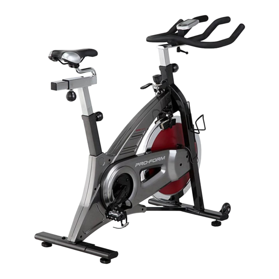
BEFORE YOU BEGIN Thank you for selecting the new PROFORM ® reading this manual, please see the front cover of this SPX exercise bike. Cycling is an effective exercise manual. To help us assist you, note the product model for increasing cardiovascular fitness, building endur- number and serial number before contacting us. -
Page 5: Assembly
ASSEMBLY •• To hire an authorized service technician to •• In addition to the included tool(s), assembly assemble this product, call 1-800-445-2480. requires the following tools: one Phillips screwdriver •• Assembly requires two persons. one adjustable wrench •• Place all parts in a cleared area and remove the packing materials. - Page 6 3. Identify the Right Pedal (35). Using an adjustable wrench, firmly tighten the Right Pedal (35) clockwise into the Right Crank Arm (26). Tighten the Left Pedal (not shown) counter- clockwise into the Left Crank Arm (not shown). 4. Orient the Handlebar Post (4) as shown. Locate the Adjustment Knob (23) on the front of the Frame (1).
- Page 7 6. Orient the Seat Post (2) as shown. Locate the Adjustment Knob (23) on the rear of the Frame (1). Loosen the Adjustment Knob and pull it outward. Then, insert the Seat Post (2) into the Frame. Move the Seat Post (2) upward or downward to the desired position, release the Adjustment Knob (23) into an adjustment hole in the Seat Post, and then tighten the Adjustment Knob.
- Page 8 8. Attach the Water Bottle Holder (74) to the Frame (1) with two M5 x 12mm Screws (63) and two M5 Washers (60). 9. Attach the Console Bracket (78) to the Handlebar (5) with two Bracket Screws (76). 10. The Console (75) requires two AAA batteries (not included);...
- Page 9 11. Attach the Console (75) to the Console Bracket (78) with a Console Screw (77). 12. The Transmitter (81) requires two AAA bat- teries (not included); alkaline batteries are recommended. Remove the battery cover from the front of the Transmitter (81), and insert batteries into the bat- tery compartment.
-
Page 10: How To Use The Exercise Bike
13. Plug the Reed Switch (80) into the Transmitter (81). Insert the other end of the Reed Switch (80) into the Clamp (82). Rotate the Flywheel (36) until the Magnet (84) is aligned with the end of the Reed Switch (80). Move the Reed Switch (80) so that the gap between the Reed Switch and the Magnet (84) is about 1/8 in. - Page 11 HOW TO ADJUST THE SEAT POST HOW TO ADJUST THE PEDAL STRAPS For effective exercise, the seat should be at the proper To tighten the pedal straps (see the drawing on page height. As you pedal, there should be a slight bend in 4), simply pull the ends of the pedal straps.
- Page 12 CONSOLE DIAGRAM HOW TO PERSONALIZE CONSOLE SETTINGS 1. Turn on the console. Press any button to turn on the console. 2. Enter the setup mode. First, press the Left but- ton repeatedly until the word SPEED appears in the lower display. Then, press and hold the Right button for several seconds to enter the setup mode.
- Page 13 4. Define the target heart rate zone if desired. 6. Select a unit of measurement if desired. The maximum heart rate The console can display speed, distance, and will flash in the middle left weight in standard or metric measurements. display.
- Page 14 HOW TO SET THE CLOCK HOW TO USE THE CONSOLE 1. Turn on the console. 1. Turn on the console. Press any button to turn on the console. Press any button to turn on the console. 2. Wear an optional heart rate monitor if desired. 2.
- Page 15 The lower display——This display can show the fol- To turn on the console backlight for a few sec- lowing workout information: onds, press the Right button once at any time. Speed (SPEED)——This Note: The console can display speed and dis- display shows your tance in either miles or kilometers.
-
Page 16: Fcc Information
HOW TO USE THE HEART RATE ALARM THE OPTIONAL CHEST HEART RATE MONITOR The heart rate alarm will alert you when your heart Whether your goal is to burn fat or to strengthen your rate is below or above a defined target heart rate cardiovascular system, the key to achieving the best zone. -
Page 17: Exercise Guidelines
EXERCISE GUIDELINES Burning Fat——To burn fat effectively, you must exer- WARNING: cise at a low intensity level for a sustained period of Before beginning this time. During the first few minutes of exercise, your or any exercise program, consult your physi- body uses carbohydrate calories for energy. -
Page 18: Part List
PART LIST Model No. PFEX05010.1 R1012A Key No. Qty. Description Key No. Qty. Description Frame Flywheel Bearing Seat Post Crank Bearing Seat Carriage Wheel Bearing Handlebar Post Flywheel Snap Ring Handlebar Crank Snap Ring Tension Bracket T1 Nut Rear Stabilizer Self-tapping Screw Front Stabilizer Flange Nut... -
Page 19: Exploded Drawing
EXPLODED DRAWING Model No. PFEX05010.1 R1012A... -
Page 20: Ordering Replacement Parts
ORDERING REPLACEMENT PARTS To order replacement parts, please see the front cover of this manual. To help us assist you, be prepared to provide the following information when contacting us: •• the model number and serial number of the product (see the front cover of this manual) ••...
Need help?
Do you have a question about the 590 Spx Bike and is the answer not in the manual?
Questions and answers