Sign In
Upload
Download
Table of Contents
Contents
Add to my manuals
Delete from my manuals
Share
URL of this page:
HTML Link:
Bookmark this page
Add
Manual will be automatically added to "My Manuals"
Print this page
×
Bookmark added
×
Added to my manuals
Manuals
Brands
Electro-Voice Manuals
Amplifier
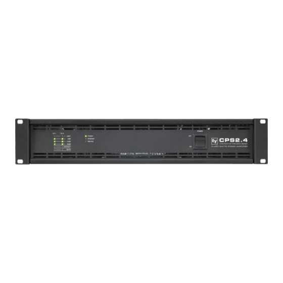
ELETRO-VOICE CPS2.4
Owner's manual
Electro-Voice CPS2.4 Owner's Manual
Contractor precision series
Hide thumbs
Also See for CPS2.4
:
Owner's manual
(36 pages)
,
Technical specifications
(2 pages)
1
2
Table Of Contents
3
4
5
6
7
8
9
10
11
12
13
14
15
16
17
18
19
20
21
22
23
24
page
of
24
Go
/
24
Contents
Table of Contents
Bookmarks
Table of Contents
English
Table of Contents
Important Safety Instructions
Important Service Instructions
Introduction
Welcome
Unpacking and Inspection
Scope of Delivery and Warranty
Features and Description
Responsibility of the User
Installation
Controls, Indicators and Connections
Operating Voltage
Mains Switch
Mounting
Ventilation
Groundlift
High Pass Filter (HPF)
Power on Delay
Selecting the Mode of Operation and Audio Output Cabeling
Audio Input Cabeling
Operation
Volume Control
Indications
Standby Mode (POWER REMOTE)
Fan Cooling
Options
Rcm-810
German
Specifications/Technische Daten
Einführung
Willkommen
Auspacken und Inspektion
Lieferumfang und Garantie
Eigenschaften & Beschreibung
Verantwortung des Betreibers
Mains Operation & Resulting Temperature
Installation
Bedienelemente, Anzeigen und Anschlüsse
Betriebsspannung
Netzschalter
Einbau
Kühlung
Block Diagram / Blockschaltbild
Groundlift
Hochpassfilter (HPF)
Einschaltverzögerung
Dimensions / Abmessungen
Betriebsart (MODE) und Verkabelung des Audio-Ausgangs
Verkabelung des Audio-Eingangs
Advertisement
Quick Links
1
Features and Description
2
Controls, Indicators and Connections
3
Power on Delay
4
Selecting the Mode of Operation and Audio Output Cabeling
5
Audio Input Cabeling
6
Specifications/Technische Daten
Download this manual
OWNER'S MANUAL
BEDIENUNGSANLEITUNG
Table of
Contents
Previous
Page
Next
Page
1
2
3
4
5
Advertisement
Table of Contents
Need help?
Do you have a question about the CPS2.4 and is the answer not in the manual?
Ask a question
Questions and answers
Related Manuals for Electro-Voice CPS2.4
Amplifier Electro-Voice ELETRO-VOICE CPS2.12 Owner's Manual
Contractor precision series (36 pages)
Amplifier Electro-Voice Contractor Precision CPS2.4 Technical Specifications
High-efficient, lightweight two-channel power amplifier (2 pages)
Amplifier Electro-Voice Contractor Precision CPS1 Technical Specifications
Electrovoice contractor precision cps1: specifications (1 page)
Amplifier Electro-Voice Contractor Precision CPS1 Owner's Manual
Electrovoice contractor precision cps1: user guide (9 pages)
Amplifier Electro-Voice Contractor Precision CPS1 Brochure & Specs
Electrovoice contractor precision cps1: product brochure (2 pages)
Amplifier Electro-Voice CPS 1 Service Manual
(19 pages)
Amplifier Electro-Voice CPS 3 Owner's Manual
Contractor precision series (9 pages)
Amplifier Electro-Voice ELETRO-VOICE CPS2.6 Owner's Manual
Contractor precision series (24 pages)
Amplifier Electro-Voice Contractor Precision CPS2T Specifications
Commercial stereo power amplifier (2 pages)
Amplifier Electro-Voice Contractor Precision CPS2T Owner's Manual
Electrovoice contractor precision cps2t: user guide (12 pages)
Amplifier Electro-Voice Contractor Precision CPS4.5 Owner's Manual
Contractor precision series (40 pages)
Amplifier Electro-Voice High-Efficient, Lightweight Two-Channel Power Amplifier CPS2.8 Specification Sheet
Contractor precision series high-efficient, lightweight two-channel power amplifier (2 pages)
Amplifier Electro-Voice CPS 3 Service Manual
Contractor precision series (54 pages)
Amplifier Electro-Voice CONTRACTOR PRECISION Series Service Manual
(54 pages)
Amplifier Electro-Voice Compact Precision CP1200 Owner's Manual
Electrovoice compact precision cp1200: user guide (36 pages)
Amplifier Electro-Voice CP3000S Owner's Manual
Cp series (36 pages)
This manual is also suitable for:
Cps2.6
Cps2.12
Cps2.9
Contractor precision cps2.4
Contractor precision cps2.6
Contractor precision cps2.12
...
Show all
Contractor precision cps2.9
Table of Contents
Print
Rename the bookmark
Delete bookmark?
Delete from my manuals?
Login
Sign In
OR
Sign in with Facebook
Sign in with Google
Upload manual
Upload from disk
Upload from URL


Need help?
Do you have a question about the CPS2.4 and is the answer not in the manual?
Questions and answers