Advertisement
Quick Links
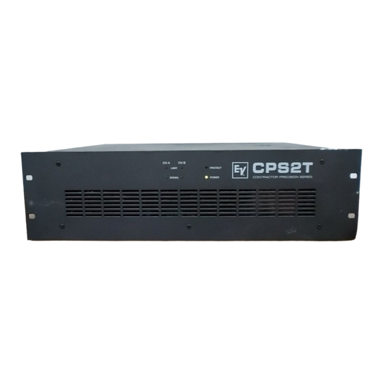
CPS2T CONTRACTOR PRECISION SERIES
Features
2 x 600 watts output power capacity
floating 100 V / 70 V / 25 V power outputs (isolated outputs)
low impedance outputs (direct outputs)
bridged mode operation, switchable
mains supply 120V / 230 V AC 50/60 Hz
POWER REMOTE function
service mains switch
active ventilation via 2 temperature-controlled DC-fans
electronically balanced inputs
routing switch for parallel linked operation
input gain controls
integrated audio limiters
power-on switching noise suppression
protection circuitry: DC/HF, Back-EMF, output voltage overload limiters, initial inrush current limiter,
output peak current limiter, output transformer saturation protection (TSP)
18 dB/oct. HPF filter at 45 Hz
SIGNAL and LIMIT indication for optical monitoring
thermal overload protection for the heat sink and the internal power supply, with PROTECT-function
input transformers for balanced, floating operation are optionally available
XLR-type and binding post clamping input connectors
19" frame size, 3 RU
OWNER'S MANUAL
BEDIENUNGSANLEITUNG
Advertisement

Subscribe to Our Youtube Channel
Related Manuals for Electro-Voice Contractor Precision CPS2T


Summary of Contents for Electro-Voice Contractor Precision CPS2T
- Page 1 CPS2T CONTRACTOR PRECISION SERIES Features 2 x 600 watts output power capacity floating 100 V / 70 V / 25 V power outputs (isolated outputs) low impedance outputs (direct outputs) bridged mode operation, switchable mains supply 120V / 230 V AC 50/60 Hz POWER REMOTE function service mains switch active ventilation via 2 temperature-controlled DC-fans...
-
Page 2: Important Service Instructions
Description............3 Installation Notes . - Page 3 DESCRIPTION Especially designed for permanent installations, the CPS2T power amplifier offers performance-consi- stent and reliable operation of PA-systems with 2 individual loudspeaker lines, each. Therefore, power amplifier is most suitable for company intercom, alarm and background music transmission installations in offices and commercial areas, congregation and sport centers, schools, houses of worship, hotels, hospitals, shopping malls and super markets, cruise ships, and other similar applications.
- Page 4 Installation Notes Generally, it is important to install the power amplifier in a way, that ensures unhindered front-to-rear air circulation. When installing the power amplifier in a closed rack-shelf system, please make sure that adequate air-flow is guaranteed. The space between the rear panel of the amplifier and the inner wall of the rack-case has to be at least 60 mm x 330 mm.
- Page 5 Inputs INPUT CHANNEL A&B With an input sensitivity of 775 mV = 0 dBu and an input impedance of 20 kohms, the electronically balanced inputs – INPUT CHANNEL A&B – are meant for the connection of audio controllers, mixing consoles, etc.
- Page 6 B. If the switch is set to its dual/stereo position, channels A and B are separately amplified (two channel or stereo mode). Power Outputs A&B The loudspeaker cables are connected to the power amplifier through high-performance binding posts –...
- Page 7 Power Outputs – AUDIO TRANSFORMER OUTPUTS The two integrated output transformers convert the power amplifier’s nominal output voltage to the commonly used loudspeaker line voltage standards – 70 V, 100 V and 25V. These voltages are simultaneously present at the correspondent floating outputs of the binding post strip. The two power amplifier channels can be operated using any possible output voltage combination.
- Page 8 Power Outputs - Isolated Outputs 25 V The floating 25 V output is mainly used for driving low impedance loudspeaker systems (4 - 16 ohms). Because of the effect of line attenuation, the distance between power amplifier and loudspeaker systems should not exceed 50 meters.
- Page 9 (+)-pole of the correspondent loudspeaker system while the loudspeakers (–)-pole has to be connected to the (+)-output connector of channel B. The output voltage of each power amplifier stage A&B is present at the binding post strip, but utilization is not recommended because of the negative correlation.
- Page 10 GROUND Lift Switch The ground lift switch is a perfect means for eliminating possible ground noise loops. In case the power amplifier is operated together with other equipment inside of a rack shelf system, the switch should be set to its GROUNDED position.
- Page 11 Protection Circuitry The CPS-Series power amplifiers are equipped with extensive protection circuitry: initial current inrush limiter power-on delay RF and DC protection Back-EMF protection limiters for the audio signals output peak-current-limiters thermal overload of the heat sink thermal overload of the mains transformer output voltage overload limiters output transformer saturation protection (TSP) High-level signals in the low frequency range can drive the output transformers of power amplifiers that...
- Page 12 Mains Operation And Leakage Power The mains power consumption as well as the leakage power is stated for driving the power amplifier at different levels. All the values were measured at nominal load via the 100 V output with two channels driven.
Need help?
Do you have a question about the Contractor Precision CPS2T and is the answer not in the manual?
Questions and answers