Table of Contents
Advertisement
Available languages
Available languages
Advertisement
Table of Contents

Related Manuals for Electro-Voice ELETRO-VOICE CPS2.12


Summary of Contents for Electro-Voice ELETRO-VOICE CPS2.12
- Page 1 OWNER’S MANUAL BEDIENUNGSANLEITUNG...
-
Page 3: Table Of Contents
Introduction ..............5 Welcome . -
Page 4: Important Service Instructions
Read these instructions. Keep these instructions. Heed all warnings. Follow all instructions. Do not use this apparatus near water. Clean only with a dry cloth. Do not cover any ventilation openings. Install in accordance with the manufacture’s instructions. Do not install near heat sources such as radiators, heat registers, stoves, or other apparatus (including amplifiers) that produce heat. Do not defeat the safety purpose of the polarized or the grounding-type plug. -
Page 5: Introduction
1 Introduction 1.1 Welcome Thank you for choosing an Electro-Voice CPS series amplifier. Please take time to consult this manual so that you can understand all the features built into your Electro-Voice amplifier and fully utilize all its performance capabilities. - Page 6 CONTRACTOR PRECISION SERIES WARNING: The terminals marked with terminals requires installation by an instructed person or the use of ready-made leads of cords. HF-Interference (FCC Information USA) 1. IMPORTANT: Do not modify this unit! Changes or modifications not expressly approved by the manufacturer could void the user‘s authority, granted by the FCC, to operate the equipment.
-
Page 7: Installation
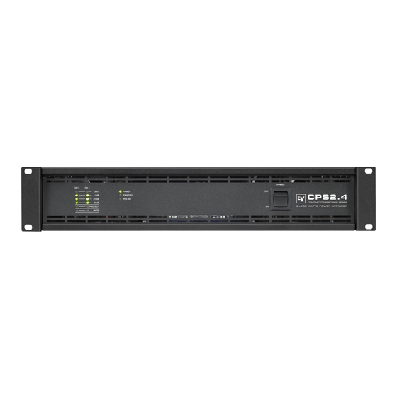
2 Installation 2.1 Controls, Indicators and Connections Front View Level Indicators for channels 1 and 2 Protections Indicator (PROTECT) Muting Indicator (MUTE) for channels 1 and 2 Power On/Off Indicator (POWER) Standby Indicator (STANDBY) Remote Amplifier Indicator (IRIS-Net) Mains Switch Rear View Mains Input Ground Lift Switch (CIRCUIT... -
Page 8: Operating Voltage
2.5 Ventilation As with all Electro-Voice power amps with fan cooling, the airflow direction is front- to-rear, obviously because there is more cold air outside of the rack case than inside. The power amplifier remains cooler and dissipating the developing waste heat in a specific direction gets easier. -
Page 9: Groundlift
CAUTION: Blocking/closing the power amp’s ventilation louvers is not permissible. Without sufficient cooling/ventilation, the power amplifier may automatically enter protect mode. Keep ventilati- on louvers free from dust to ensure unhindered airflow. Do not use the power amplifier near heat sources, like heater blowers, stoves or any other heat radiating devices. -
Page 10: Selecting The Mode Of Operation And Audio Output Cabeling
4 ohms. Extremely high voltages can be present at the output. The connected speaker sy- stems must be able to handle such voltages. Make sure to completely read and fully observe power rating specifications of the speaker systems to be used and to check them against the output power capacity of the power amp. -
Page 11: Audio Input Cabeling
CONTRACTOR PRECISION SERIES 2.10 Audio Input Cabeling Inputs are electronically balanced. Whenever possible, using balanced audio signal feeds at the input of the power amplifier is always preferred. Unbalanced connections should only be used if the cables are very short and no interfering signals are to be expected in the vicinity of the power amplifier. -
Page 12: Operation
Whatever caused the fault – e.g. a short-circuited speaker cable – needs to be remedied. In case of thermal overload you have to wait until the power amplifier automatically regains normal operation. -
Page 13: Standby Mode (Power Remote)
3.3 Standby Mode (POWER REMOTE) POWER REMOTE provides a simple way to remotely power-on/off the power amplifier. The POWER REMOTE function is only useful for appliances not employing a Remote Control Modul. Controlling CPS amplifiers with Remote Control Module installed per POWER REMOTE is not recommended. Leaving the pins of POWER REMOTE socket open the appliance power is switched on. -
Page 14: Options
CONTRACTOR PRECISION SERIES 4 Options Installing one of the optionally available extension modules in the extension slot on the rear panel lets you expand the power amp’s functional range. As an example, the following paragraphs describe the RCM-810 Remote Control Module. Please read and follow the instructions provided in the documentation that you have received together with each extension module. -
Page 15: Status Led
HIGH 1...F 0...F 0...F 0...F 0...F 0...F 0...F 0...F Address 0 (00 hex, delivery status) disables remote communication between the RCM-810 and the bus. The module does not appear in the system, even though it is physically connected to the CAN-bus. 2 STATUS LED The STATUS-LED is for monitoring the communication on the CAN bus. -
Page 16: Control Port
CONTRACTOR PRECISION SERIES Illustration 4.2: Pin-assignment of CAN jack and CAN plug 4 CONTROL PORT The CONTROL PORT of the RCM-810 provides two control inputs, two control outputs and reference connections for +5V and ground. The control inputs are configurable via IRIS-Net™. They can be used for example for switching between power on / standby modes. - Page 17 CONTRACTOR PRECISION SERIES Owner‘s Manual...
-
Page 18: Wichtige Sicherheitshinweise
Lesen Sie diese Hinweise. Heben Sie diese Hinweise auf. Beachten Sie alle Warnungen. Richten Sie sich nach den Anweisungen. Betreiben Sie das Gerät nicht in unmittelbarer Nähe von Wasser. Verwenden Sie zum Reinigen des Gerätes ausschließlich ein trockenes Tuch. Verdecken Sie keine Lüftungsschlitze. Beachten Sie bei der Installation des Gerätes stets die entsprechenden Hinweise des Herstellers. Vermeiden Sie die Installation des Gerätes in der Nähe von Heizkörpern, Wärmespeichern, Öfen oder anderer Wärmequellen. -
Page 19: Einführung
1 Einführung 1.1 Willkommen Vielen Dank, dass Sie sich für eine Endstufe der Electro-Voice Contractor Precision Serie entschieden haben. Bitte lesen Sie diese Bedienungsanleitung aufmerksam durch, damit Sie Ihren neuen Electro-Voice Verstärker optimal nutzen können. 1.2 Auspacken und Inspektion Öffnen Sie die Verpackung und entnehmen Sie die Endstufe. Überprüfen Sie die Endstufe auf äußere Beschädigungen, die während des Transports zu Ihnen aufgetreten sein können. -
Page 20: Installation
CONTRACTOR PRECISION SERIES 2 Installation 2.1 Bedienelemente, Anzeigen und Anschlüsse Frontseite Rückseite Netzeingang Schalter Groundlift (CIRCUIT ⊥ TO CHASSIS SWITCH) POWER-REMOTE-Buchse (POWER REMOTE) Einschaltverzögerungs-Wahlschalter (ON DELAY) Erweiterungssteckplatz Audioeingang (INPUT) je Kanal Eingangspegel-Regler je Kanal (LEVEL) Schalter Endstufen-Betriebsart (MODE) Schalter Hochpass-Filter (HPF) Typenschild Endstufenausgang (CH 1, CH 2, BRIDGED) Bedienungsanleitung... -
Page 21: Betriebsspannung
Hilfe von Käfigmuttern und Befestigungsschrauben. Geeignete Rackwinkel sind als Zubehör erhältlich. 2.5 Kühlung Bei allen lüftergekühlen Endstufen von Electro-Voice strömt die Luft von der Frontseite zur Rückseite, da kühle Frischluft eher außerhalb des Racks zur Verfügung steht als innerhalb. Die Endstufe bleibt kühler und die entstehende Abwärme kann gezielter abgeführt werden. -
Page 22: Groundlift
CONTRACTOR PRECISION SERIES ACHTUNG: Die Lüftungsöffnungen der Endstufe dürfen nicht blockiert/verschlossen werden. Bei fehlen- der Kühlung kann sich die Endstufe automatisch abschalten. Halten Sie alle Lüftungsöffnun- gen frei von Staubablagerungen, die den Luftstrom behindern würden. Betreiben Sie die Endstufe nicht in der Nähe von Wärmequellen wie Heizlüftern, Öfen oder an- deren Geräten, die Hitze abstrahlen. -
Page 23: Betriebsart (Mode) Und Verkabelung Des Audio-Ausgangs
2.9 Betriebsart (MODE) und Verkabelung des Audio-Ausgangs Der Schalter MODE an der Rückseite bestimmt die Betriebsart der Endstufe. Mögliche Schalterstellungen sind DUAL, PARALLEL und BRIDGED. DUAL In der Betriebsart DUAL arbeiten beide Kanäle der Endstufe unabhängig voneinander. Diese Betriebsart wird bei allen 2-kanaligen Anwendungen wie Stereobetrieb verwendet. Über die Eingangspegel-Regler an der Rückseite der Endstufe lässt sich die Verstärkung der Kanäle getrennt justieren. -
Page 24: Verkabelung Des Audio-Eingangs
CONTRACTOR PRECISION SERIES 2.10 Verkabelung des Audio-Eingangs Die Signal-Eingänge INPUT sind elektronisch symmetrisch ausgelegt. Falls möglich, sollte stets ein symmetrisches Audiosignal am Eingang der Endstufe verwendet werden. Falls das/die Anschlusskabel sehr kurz sind und keine Störsignale in der Umgebung der Endstufe zu erwarten sind, kann auch ein unsymmetrisches Signal angeschlossen werden. -
Page 25: Betrieb
3 Betrieb 3.1 Eingangspegel-Regler In den Betriebsarten DUAL und PARALLEL regeln die Eingangspegel-Regler LEVEL an der Rückseite der Endstufe die Verstärkung des jeweiligen Kanals. Drehung nach rechts erhöht die Lautstärke, Drehung nach links verringert die Lautstärke. In der Betriebsart BRIDGED regelt nur der Drehknopf von Kanal 1 (CH 1) die Lautstärke, die Drehknopf-Einstellung von Kanal 2 (CH 2) wird ignoriert. -
Page 26: Standby-Modus (Power Remote)
CONTRACTOR PRECISION SERIES 3.3 Standby-Modus (POWER REMOTE) Über den Anschluss POWER REMOTE kann die Endstufe auf einfache Weise ferngesteuert ein- und ausgeschaltet werden. Die POWER REMOTE Funktion kommt nur bei Geräten ohne Remote Control Modul zum Tragen. Eine Steuerung von Geräten mit Remote Control Modul per POWER REMOTE ist nicht empfohlen. -
Page 27: Optionen
CONTRACTOR PRECISION SERIES 4 Optionen Durch den Einbau eines optionalen Zusatzmoduls in den Erweiterungssteckplatz an der Rückseite kann der Funktionsumfang der Endstufe erhöht werden. Als Beispiel wird im folgenden das RCM-810 Remote Control Modul aufgeführt. Bitte beachten Sie bei allen Zusatzmodulen die jeweils mitgelieferte Bedienungsanleitung 4.1 RCM-810 Systembeschreibung Das RCM-810 Remote Control Modul ist ein Digital-Controller Modul für Live Sound, PA und Festinstallation. - Page 28 CONTRACTOR PRECISION SERIES 1 ADDRESS-Wahlschalter Mit den beiden Adress-Wahlschaltern wird die Netzwerk-Adresse des RCM-810 eingestellt. In einem CAN-Netzwerk können die Adressen 01 bis 250 (FA hex) verwendet werden. Die Adresseinstellung erfolgt im hexadezimalen Zahlensystem. Der Wahlschalter LOW ist für das niederwertige Digit, der Schalter HIGH für das höherwertige Digit.
- Page 29 Datenrate (in kbit/s) Tabelle 4.2: Datenrate und Buslänge in CAN-Netzwerken Abbildung 4.2: Belegung der CAN-Buchse und des CAN-Steckers Name CAN_GND CAN_H (+) CAN_L (-) Tabelle 4.3: Übersicht CAN-Stecker 4 CONTROL PORT Der CONTROL PORT des RCM-810 enthält zwei Steuereingänge, zwei Steuerausgänge und Referenzanschlüsse für +5V und Masse.
-
Page 30: Specifications/Technische Daten
CONTRACTOR PRECISION SERIES Specifications/Technische Daten Amplifier at rated conditions, both channels driven, 8 Ω load, unless otherwise specified. Load Impedance Maximum Midband Output Power THD = 1%, 1 kHz, Dual Channel Rated Output Power THD < 0.1%, 20 Hz...20 kHz Maximum Single Channel Output Power Dynamic-Headroom, IHF-A Maximum Single Channel Output Power... -
Page 31: Mains Operation & Resulting Temperature
5.1 Mains Operation & Resulting Temperature CPS2.4 Idle Max. Output Power @ 8 Ω Max. Output Power @ 4 Ω 1/3 Max. Output Power @ 4 Ω 1/8 Max. Output Power @ 4 Ω 1/8 Max. Output Power @ 4 Ω 1/8 Max. - Page 32 CONTRACTOR PRECISION SERIES CPS2.9 Idle Max. Output Power @ 8 Ω Max. Output Power @ 4 Ω 1/3 Max. Output Power @ 4 Ω 1/8 Max. Output Power @ 4 Ω 1/8 Max. Output Power @ 4 Ω 1/8 Max. Output Power @ 4 Ω Normal Mode (-10 dB) @ 4 Ω...
-
Page 33: Block Diagram / Blockschaltbild
CONTRACTOR PRECISION SERIES 5.2 Block Diagram / Blockschaltbild Owner‘s Manual / Bedienungsanleitung... -
Page 34: Dimensions / Abmessungen
CONTRACTOR PRECISION SERIES 5.3 Dimensions / Abmessungen Owner‘s Manual / Bedienungsanleitung... - Page 36 AMERICAS Bosch Security Systems, Inc. 12000 Portland Ave South Burnsville, MN 55337, USA USA-Phone:1-800-392-3497 Fax: 1-800-955-6831 Canada-Phone: 1-866-505-5551 Fax:1-866-336-8467 Latin America-Phone: 1-952-887-5532 Fax: 1-952-736-4212 Subject to change withou prior notice. EUROPE, AFRICA & MIDDLE-EAST ASIA & PACIFIC RIM Bosch Sicherheitssysteme GmbH Telex Pte.
Need help?
Do you have a question about the ELETRO-VOICE CPS2.12 and is the answer not in the manual?
Questions and answers