Table of Contents
Advertisement
Advertisement
Table of Contents

Related Manuals for Chauvet Stage Designer 50


Summary of Contents for Chauvet Stage Designer 50
-
Page 1: User Manual
Snapshot Use on Dimmer Outdoor Use Sound Activated Master/Slave 115 V / 230 V Switch Replaceable Fuse User Serviceable Duty Cycle User Manual Chauvet, 5200 NW 108th Avenue, FL 33351 (800) 762-1084 – (954) 929-1115 FAX (954) 929-5560 www.chauvetlighting.com... -
Page 2: Table Of Contents
Dmx Data Cable ............................ 21 Cable Connectors ..........................21 ............................22 IXTURE INKING ..........................22 ETURNS ROCEDURE ............................... 22 LAIMS ......................... 23 ETTING THE TARTING DDRESS ........................24 ENERAL ROUBLESHOOTING ..........................24 ONTACT NFORMATION ......................... 25 ECHNICAL PECIFICATIONS Stage Designer 50 January 31, 2012... -
Page 3: What Is Included
Manual Conventions CHAUVET® manuals use the following conventions to differentiate certain types of information from the regular text. EANING... -
Page 4: Safety Instructions
Do not operate this device in more than 104° F (40° C) ambient temperature conditions. There are no user serviceable parts inside the unit. Do not open the housing or attempt any repairs yourself. In the unlikely event your unit may require service, please contact CHAUVET® at: 954-929-1115.2. Introduction Stage Designer 50... -
Page 5: Features
The Stage Designer 50™ is a universal intelligent lighting controller. It allows the control of 48 channels with 96 scene/chase playback faders. Each scene/chase can contain up to 1000 individual steps, or looks. On the surface, when in the CHASE◄►SCENE mode, there are 12 physical faders for the playback of the saved programs. -
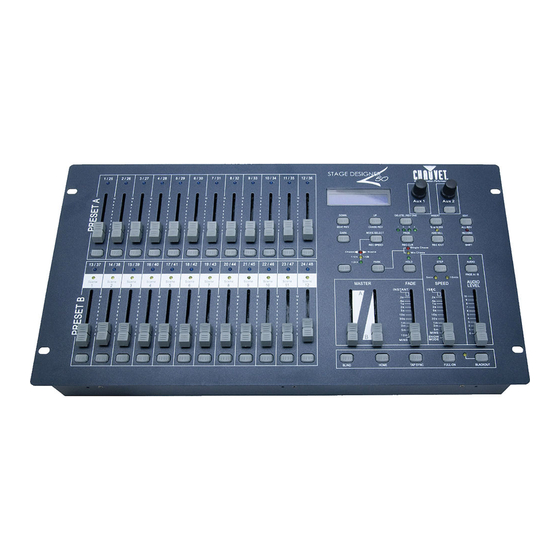
Page 6: Product Overview (Front)
Product Overview (front) Stage Designer 50 January 31, 2012... - Page 7 In Add mode, multiple scenes or Flash buttons will be on at the same time; In Kill mode, pressing any Flash button will kill any other scenes or programs; Rec Exit is used to exit from Program or Edit mode. Stage Designer 50 January 31, 2012...
-
Page 8: Product Overview (Rear Panel)
This jack accepts a line level audio input signal ranging from 100mV to 1Vpp Remote Input Blackout and Full On may be controlled by a remote control using a standard ¼´jack DC Input DC 12-20V, 500mAMin. Stage Designer 50 January 31, 2012... -
Page 9: Common Terms
Patching refers to the process of assigning faders to a DMX channel within a fixture. § Playbacks can be either scenes or chases that are directly called to execution by the user. A playback can also be considered program memory that can be recalled during a show. Stage Designer 50 January 31, 2012... -
Page 10: Operating Instructions
Setup Set ting up t he Sys t em Place the Stage Designer 50™ on a level surface. Note! The Stage Designer 50™can also be rack mounted, occupying six rack spaces (6U). Plug the AC to DC power supply into the system back panel and into the mains outlet. -
Page 11: Programming
Press and hold the Edit button & tap the Flash button (13-24) of the Scene you wish to edit. Release the Edit button. The relevant Scene Led should light, indicating you are in Edit mode. Stage Designer 50 January 31, 2012... -
Page 12: Erase A Program
Scene fader. If you are not satisfied with the scene, you may press and hold the Record button & tap the Page/REC CLR button. All LEDs will flash, indicating the scenes have been cleared. Stage Designer 50 January 31, 2012... -
Page 13: Delete A Step Or Steps
Then, you may tap the Flash buttons until you are satisfied with the new Scene. Repeat steps 2, 3, and 4 until all the steps have been modified. Exit EDIT enable. Stage Designer 50 January 31, 2012... -
Page 14: Playback
AUDIO mode is active. Use the Audio Level slider to adjust the sensitivity. To return to normal mode, tap the Audio button a second time, causing its LED to go out. AUDIO mode is disengaged. Stage Designer 50 January 31, 2012... -
Page 15: Playing A Scene With The Speed Slider
This is the process of assigning the Auxiliary controls. These will act as shortcuts and are most commonly used for DMX strobe lights or DMX fog machines. However, they are not limited to these functions, such as Pan/tilt control-very useful for remote followspot controls. Stage Designer 50 January 31, 2012... - Page 16 Flash button for the channel you wish to assign the auxiliary control to. This sets the channel assignment. The corresponding Led above the channel will light, indicating that the channel has ben assigned. Record exit. Stage Designer 50 January 31, 2012...
-
Page 17: Midi Operation
The display reads MIDI CHANNEL The MIDI controller will take precedence over the IN to indicate channel setup is available. Stage Designer 50’s functions. For example, for notes 25-48, the LEDs for each channel on the Select the MIDI control channel (1~16) by DMX board will not light up when a MIDI controller tapping Flash buttons 1~16. -
Page 18: Setting Midi Out
Therefore, be sure that the other device has previously been setup to receive the transfer. During FILE DUMP, all other operations will cease to function. If errors or power failure occurs, FILE DUMP will be interrupted and stop. Stage Designer 50 January 31, 2012... -
Page 19: Appendix
This drawing provides a general illustration of the 4. After the last fixture, connect a DMX DMX input/output terminator. panel of a lighting fixture. Continue the link Stage Designer 50 January 31, 2012... -
Page 20: Data Cabling
Data Cabling To link fixtures together you must obtain data cables. You can purchase CHAUVET® certified DMX cables directly from a dealer/distributor or construct your own cable. If you choose to create your own cable please use data-grade cables that can carry a high quality signal and are less prone to electromagnetic interference. -
Page 21: Fixture Linking
Package must be clearly labeled with a Return Merchandise Authorization Number (RMA #). Products returned without an RMA # will be refused. Call CHAUVET® and request RMA # prior to shipping the fixture. Be prepared to provide the model number, serial number and a brief description of the cause for the return. -
Page 22: Setting The Starting Address
If this is your first time addressing a fixture using the DMX-512 control protocol, we suggest jumping to the Appendix Section and reading the heading “DMX Primer”. It contains very useful information that will help you understand its use. Stage Designer 50 January 31, 2012... -
Page 23: General Troubleshooting
No laser output Bounce mirror motor may have ü shifted during shipping; readjust If you still have a problem after trying the above solutions, please contact CHAUVET® Technical Support. Contact Information World Headquarters United Kingdom & Ireland CHAUVET®... -
Page 24: Technical Specifications
Data pin configuration ..........pin 1 shield, pin 2 (-), pin 3 (+), pins 4+5 (not used) Protocols........................DMX-512 USITT ORDERING INFORMATION Stage Designer™ 50 ..................... STAGEDESIGNER50 WARRANTY INFORMATION Warranty ......................2-year limited warranty Stage Designer 50 January 31, 2012...
Need help?
Do you have a question about the Stage Designer 50 and is the answer not in the manual?
Questions and answers
how do i transfer the (A ) preset settings to the (B) preset panel ?
To transfer the A preset settings to the B preset panel on the Chauvet Stage Designer 50, use Crossfade Mode. In this mode, PRESET A and PRESET B both control the same 12 channels, depending on the selected page (Page A for channels 1–12, Page B for channels 13–24). Use the MASTER faders to fade between the A and B presets, effectively transferring the look from A to B by adjusting the faders. There is no direct "copy" function; instead, you use the faders to match settings manually.
This answer is automatically generated