IAME Parilla 125cc LEOPARD TaG Assembly Instructions And User's Manual
Hide thumbs
Also See for Parilla 125cc LEOPARD TaG:
- Assembly instructions and user's manual (38 pages) ,
- Assembly instructions and user's manual (38 pages)
Table of Contents
Advertisement
Advertisement
Table of Contents

Subscribe to Our Youtube Channel
Related Manuals for IAME Parilla 125cc LEOPARD TaG


Summary of Contents for IAME Parilla 125cc LEOPARD TaG
- Page 1 125cc LEOPARD TaG engine ASSEMBLY INSTRUCTIONS USER MANUAL MAN-016 D...
-
Page 2: Table Of Contents
INDEX Page GENERAL DESCRIPTION OF THE "LEOPARD" ENGINE CHARACTERISTICS OF THE "LEOPARD" ENGINE – OPERATIONAL LIMITS 1- Contents of the packing 2- Motor identification Number 3- Preparation and installation of the engine on the chassis 3.1 Install the water cooling system 3.2 Exhaust header assembly 3.3 Preparation and installation of the motor-mount 3.4 Install the carburetor... -
Page 3: General Description Of The "Leopard" Engine
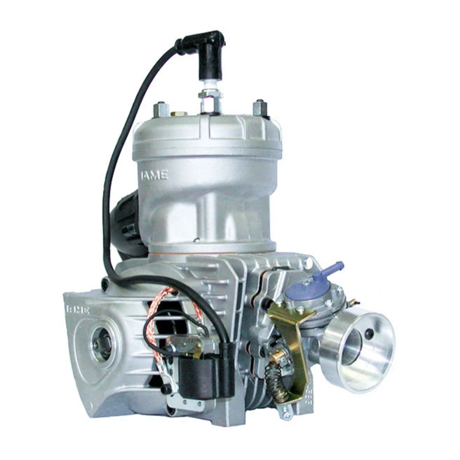
GENERAL DESCRIPTION OF THE "LEOPARD" ENGINE This engine of the "TaG" series (Touch and Go) has been expressly designed and developed for the powering of karts for hobby racing on closed tracks, destined for this specific purpose. When designing this new line of engines, the technical solutions already adopted for the high performance engines were used, in order to guarantee the highest reliability of components, when the operating limitations are respected. -
Page 4: Characteristics Of The "Leopard" Engine – Operational Limits
Automatic, dry, centrifugal 2. OPERATIONAL LIMITS: • Max. RPM : 15000 RPM • Min. waterTemperature: 45°c • Max. water Temperature: 90°c ATTENTION: Never exceed the above limits, no obligation of IAME exists in case the above limits are exceeded. MAN-016 D... -
Page 5: Contents Of The Packing
1- CONTENT OF THE PACKING Each Leopard engine is delivered with the under shown accessories: -125 cc LEOPARD- TaG engine EXHAUST • Flexible • Spring For Flexible • Exhaust Fiber Strip • Exhaut Header • Exhaust Muffler INDUCTION • Tillotson Carburetor •... -
Page 6: Motor Identification Number
NOTE: In case of need for spares and when contacting the IAME Support Centers, please always refer to the Motor Identification Number and to the motor model. MAN-016 D... -
Page 7: Preparation And Installation Of The Engine On The Chassis
3- PREPARATION AND INSTALLATION OF THE ENGINE ON THE CHASSIS NOTE: In case the engine is supplied already assembled on the chassis, it is at care of the assembler to follow these instructions. The final customer, in this case, can skip this section and can start reading from section 4. - Page 8 INSTALL THE BELTS AND TENSION (SEE FIG. 4). Fig.4 BEFORE INSTALLING THE RADIATOR PREASSEMBLE THE FOLLOWING COMPONENTS ASSEMBLE THE CONNECTING BRACKET ON THE RADIATOR SUPPORT BRACKET. INSTALL THE UPPER LEFT BRACKET ON THE CONNECTING BRACKET (SEE FIG. 5). UPPER LEFT BRACKET RADIATOR SUPPORT BRACKET CONNECTING BRACKET Fig.5...
- Page 9 INSTALL THE UPPER RIGHT BRACKET AND RADIATOR FIXING SUPPORT FIX TO THE RADIATOR FIXING SUPPPORT. TORQUE ALL BOLTS. UPPER RIGHT BRACKET Fig.7 PLACE THE RADIATOR SUPPORT BRACKET ON THE SIDE RAIL, BRAKE SIDE (TIGHTEN THE BOLTS BY HAND) (SEE FIG. 8). Fig.8 PLACE THE RADIATOR SO THAT THE HOLE ON THE RADIATOR FIXING SUPPORT AND...
- Page 10 SECOND HOSE APPROPRIATE LENGHT TO CONNECT, ON SIDE, FITTINGS RADIATOR OUTLET AND THE PUMP INLET AND ON THE OTHER SIDE THE FITTINGS ON THE PUMP OUTLET AND THE ENGINE INLET (SEE FIG. 10). FIX WITH STEEL CLAMPS. Fig.10 BEFORE STARTING THE ENGINE FOLLOW THESE RECOMMENDATIONS: •...
-
Page 11: Preparation And Installation Of The Motor-Mount
EXHAUST HEADER ASSEMBLY NOTE: ENGINE SUPPLIED WITH EXHAUST GASKET AND NUTS ALREADY INSERTED. WHEN THE SHIPMENT IS MADE AN EXHAUST COVER TO PROTECT THE INTERNAL PARTS. 3.2.1 REMOVE THE NUTS AND THE EXHAUST COVER. Fig.1 3.2.2 MAKE SURE THE EXHAUST GASKET IS SEATED INSTALL EXHAUST... -
Page 12: Install The Carburetor
3.3.2 BEFORE INSTALLING MOTOR MOUNT, POSITION THE ADDITIONAL MOUNT Fig.2 PLATE ON THE CRANKCASE (SEE FIG. 2) AND MAKE SURE THAT THE RUBBER RING IN SUPPORT INSERTED STARTER BODY. 3.3.3 INSTALL THE MOTOR MOUNT. MAKE 6 mm ALLEN WRENCH. SURE TO USE M8 ALLEN SCREWS WITH A LENGHT SUCH AS TO ENGAGE, IN THE Fig.3 CRANKCASE,... - Page 13 SCREWDRIVER 4.8 mm. 3.4.2 REMOVE 2 SCREWS 3.5mm ON THE Fig.5 CARB. PUMP (IN CORRESPONDENCE OF THE THROTTLE LEVER) (SEE FIG. 5). Fig.6 3.4.3 INSERT THE GAS BRACKET AND THE TWO SCREWS (SEE FIG. 6). 3 mm ALLEN WRENCH 3.4.4 INSTALL THE INTAKE SUPPORT –...
- Page 14 Fig.9 ATTENTION: WHEN REPLACING CARB GASKET ALWAYS MAKE SURE THAT THE GASKET IS INSTALLED SO THAT THE HOLE IN THE GASKET MATCHES WITH PRESSURE HOLES IN THE CARB. AND IN THE CRANKCASE: OTHERWISE THE ENGINE WON’T START. INSTALL THE CARBURETOR. N.2 NUTS M6 AND TWO WASHERS.
- Page 15 3.5.4 MOVE THE ENGINE ON THE RAILS AND OPTIMIZE THE CHAIN TENSION . ATTENTION: THE PLAY OF THE CHAIN MUST BE APPR. 15mm (½÷¾ inch) MEASURED IN THE SHOWN POINT (SEE FIG. 16) 15mm Fig.13 3.5.5 TORQUE THE CLAMP SCREWS 5mm ALLEN INSTALL THE CLUTCH COVER WITH H.T.
-
Page 16: Electrical Connection
ELECTRICAL CONNECTION (refer to the attached electrical schematic) INSTALLATION AND CONNECTION OF THE POWER PACK BOX. NOTE: THE POWER PACK BOX IS SUPPLIED ALREADY ASSEMBLED ON THE BATTERY SUPPORT (WITH BATTERY) CORRECT INSTALLATION FOLLOW THE UNDER SHOWN INSTRUCTIONS. 3.7.1 EXTRACT THE BATTERY FROM THE Fig.16 SUPPORT AFTER HAVING UNLACED THE BATTERY STRAP (SEE FIG. - Page 17 3.7.4 INSERT THE BATTERY STRAP (SEE FIG. 19). Fig.19 3.7.5 INSERT BATTERY WITH TERMINALS TOWARDS THE OUTSIDE (SEE FIG. 20). CONNECT THE BATTERY TERMINALS. SUGGESTION: NEVER CONNECT THE BATTERY UNTIL YOU ARE READY TO START THE ENGINE. SEAL THE BATTERY TERMINALS WITH PLASTIC TAPE TO AVOID THAT EVENTUAL VIBRATIONS MIGHT...
- Page 18 3.7.6.2 FILE THE PAINTING ON THE SEAT SUPPORT UP TO BARE METAL (SEE FIG.22). ATTENTION: THIS OPERATION EXTREMELY IMPORTANT UNCERTAIN GROUNDING COULD DAMAGE THE POWER PACK BOX BEYOND REPAIR. Fig.22 Fig.23 3.7.6.3 INSERT THE BOX GROUND CABLE EYELET ON THE SCREW AND TIGHTEN THE SCREW (SEE FIG.
- Page 19 Fig.26 3.8.2 CONNECT THE CABLE (RED) FROM THE POWER PACK BOX TO THE ELECTRIC STARTER (USE THE SCREW ALREADY INSTALLED ON THE CABLE) (SEE FIG. 27). Fig.27 3.8.3 FIX THE ELECTRIC STARTER AND THE CABLE (SEE FIG. 28) AND COMPLETE THE FIXING OF THE HARNESS (SEE FIG.
- Page 20 3.8.4 CONNECT THE COIL CABLE FROM Fig.30 THE POWER PACK TO THE TERMINAL ON THE COIL (SEE FIG. 30). SUGGESTION: SEAL THE TERMINAL ON THE COIL WITH PLASTIC TAPE TO AVOID THAT EVENTUAL VIBRATIONS MIGHT DISCONNECT TERMINAL. 3.8.5 GROUND THE ENGINE ATTENTION : AN INADEQUATE GROUNDING OF THE ENGINE COULD DAMAGE THE IGNITION...
- Page 21 3.8.6 PUNCTURE INSULATING MATERIAL ON THE H.T. CABLE WITH THE END OF THE CAP SPRING SO THAT THE SPRING IS IN SURE CONTACT WITH THE INTERNAL WIRE (SEE FIG. 33). Fig.33 Fig.34 3.8.7 INSERT THE SPARK PLUG CAP ON THE SPRING (SEE FIG. 34). INSTALL THE SPARK PLUG AND THE CAP OVER THE SPARK PLUG.
- Page 22 3.10 INSTALL THE EXHAUST SEE SECTION 9 FOR RECOMMENDATIONS ON THE IDEAL LENGHT OF THE EXHAUST. 3.10.1 INSTALL THE FLEXIBLE (L= 65mm – FLEXIBLE COMPLETELY CLOSED) AND THE EXHAUST HEADER (SEE FIG. 37) AND CONNECT THE EXHAUST. Fig.37 3.10.2 INSTALL THE FIBER STRIP AROUND THE FLEXIBLE AND FIX WITH THE 3 SPRINGS (SEE FIG.
-
Page 23: Gasoline And Oil
4- GASOLINE and OIL Use leaded or unleaded Premium Gasoline (92 RON+MON ) mixed with oil at 6% - (16:1). Use oils containing Castor Oil which guarantees an optimized lubrication at high temperatures. As on the other hand, use of Castor Oils creates gummy residues which give origin to carbon deposits, it is necessary to check and clean, at least every 5 ÷... -
Page 24: Carburetor Adjustment Guide
5- CARBURETOR ADJUSTMENT GUIDE ) THROTTLE ( H ) HIGH SPEED FUEL MIXTURE SPEED SCREW ( L ) LOW SPEED FUEL MIXTURE 1 T.O. RICH LEAN ¼ ¾ T.O. T.O. ½ T.O. T.O. = TURNS OPEN Normally the correct setting of the mixture screws is the following: L (close the screw completely and then open): 1 ¼... -
Page 25: Starting And Stopping The Engine
6- STARTING AND STOPPING THE ENGINE Press the green button on the Power Pack . If the engine can’t be started within 5 seconds (check that gas gets to the carb.) interrupt and try again after 15 seconds. Shorts and frequent tries are better than long ones. -
Page 26: Exhaust System
9- EXHAUST SYSTEM Before every test, make sure that the flexible is not damaged. Replace if necessary. ATTENTION: In case the flexible is damaged, metallic particles could be sucked in the engine and cause a seizure. Always make sure that the springs are well hooked and in place. In case of breakage, replace the broken spring. - Page 27 ATTENTION: Once the engine is started, avoid useless accelerations which can overheat and deteriorate the clutch. Oil the chain before each tests, immediately after each race or test, check the engine sprocket. Replace if necessary. A bad alignment of the engine sprocket with the axle sprocket or the lack of oil will damage the chain and sprocket.
- Page 28 11- INSTRUCTIONS FOR THE DISASSEMBLY / ASSEMBLY OF THE CLUTCH ATTENTION: The following operations can be performed by a skilled mechanic under the conditions to have available the dedicated tools shown on the text, otherwise it is necessary to apply to an Authorized Service Center. Refer to the following drawing during the operations.
-
Page 29: Battery
Before assemblying the clutch, wash with diluent the shaft taper, the connecting hole on the clutch body, the clutch drum and the starter ring. Clutch assembly 1. Install the starter ring on the clutch body by matching 10 mm socket the 3 holes and the dragging pin. -
Page 30: Spark Plug And Thermal Degree
ATTENTION: Always connect the - (negative) terminal before and the + (positive) terminal after. Always disconnect the battery in opposite order. Recharge the battery at least once every 6 months. Never put the battery in contact with solvents, gasolines, oils, plastifiers or rags containing such elements. -
Page 31: Choice Of The Best Sprocket Ratio
The operating limit for the Leopard engine is 15000 RPM. ATTENTION: Never exceed the above limits. No obligation of IAME exists in case the above limits are exceeded. In case the user wishes to optimize on the track the sprocket ratio in order to achieve the best possible performance, without abusing the engine, follow the under shown recommendations. - Page 32 Tab.1 Sprocket Sprocket Teeth n° - Engine sprocket Teeth n° - Engine sprocket ratio ratio Teeth n° - Teeth n° - axle sprocket axle sprocket 7,20 6,55 8,30 7,55 7,30 6,64 8,40 7,64 7,40 6,73 8,50 7,73 7,50 6,82 8,60 7,82 7,60 6,91...
- Page 33 MAN-016 D...
-
Page 34: Scheduled Maintenance
15- SCHEDULED MAINTENANCE Following some simple maintenance standards will allow the engine to perform more reliably and have a longer life. SCHEDULE COMPONENTS ACTIONS AND COMMENTS Before using Exhaust flexible Check status Exhaust springs Check status Exhaust strap Check status Exhaust muffler Check status and fixing Engine sprocket... -
Page 35: Troubleshooting
16- TROUBLESHOOTING Below are some common faults, their probable causes and suggested remedy: FAULTS PROBABLE CAUSE REMEDY Starter will not crank when Bad connections on starter cables. Check and tighten pushing the start button. Bad grounding Check connections and tighten Damaged cables Replace Battery connection loose... - Page 36 17- ENGINE PRESERVATION When engine is to remain unoperative for a long period it must be preserved as follows: Disconnect the battery and charge it periodically (see Par. 12) Disconnect carburetor and clean it Seal with tape the engine inlet and exhaust The external of the engine must be cleaned.
- Page 37 MAN-016 D...
- Page 38 MAN-016 D MAN-016 D...
Need help?
Do you have a question about the Parilla 125cc LEOPARD TaG and is the answer not in the manual?
Questions and answers