Table of Contents
Advertisement
Quick Links
Advertisement
Table of Contents

Subscribe to Our Youtube Channel
Related Manuals for Axminster C0


Summary of Contents for Axminster C0
- Page 1 Code 505100 C0 Metal Turning Lathe...
- Page 2 IMPORATANT SAFETY INSTRUCTION READ ALL INSTRUCTIONS AND WARNINGS BEFORE USING THIS TOOL Operator PLEASE REMEMBER: 1. When using electric tools, machines or equipment, basic safety precautions should always be followed to reduce the risk of fire, electric shock, and personal injury. 2.
-
Page 3: Specifications
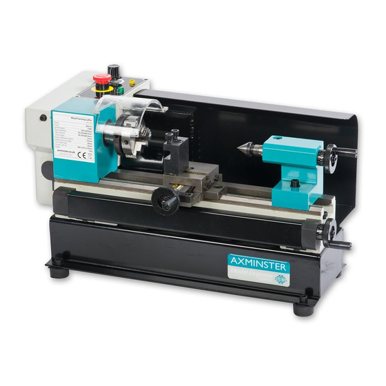
SPECIFICATIONS Max. swing over bed 100 mm Max. length of workpiece 125 mm Hole through spindle 10 mm Hole through tailstock quill 10 mm 100-3800 rpm ±10% Spindle speed (Variable speed) Motor output power 150 W Packing size 500x400x310 mm Net/Gross weight 13 / 22 kgs FEATURES... -
Page 4: The Saddle And The Cross-Slide
1. THE HEADSTOCK The motor provides a direct drive to the spindle via an internal tooth type belt. Spindle speed is variable, and is regulated by the Speed Control Knob(4). Located on the main control panel. The 3-jaw self centering chuck(8) is mounted on the spindle flange. To remove the chuck, simply remove the three securing nuts to rear of the flange allowing it to be pulled free together with three mounting studs. -
Page 5: Operation
Switch on the machine by GENTLY turning the Variable Speed control knob(4), clockwise. A click will be heard as power is turned on, but the spindle will not rotate until the knob is turned clockwise a little further. Speed will increase progressively the further the knob is turned. Run of a total 5 minutes during which time gradually increase spindle speed to its maximum. -
Page 6: Maintenance
Mark the surface of the work at the point where the cut is to end, i.e. the shoulder, using a scriber or similar means, and move the saddle so that the cutting tool is directly opposite the mark, then wind in the cross-slide so that the tool touches the surface of the work. Whilst carrying out these manovres, rotate the chuck by hand to ensure that nothing will come into contact with if when turning takes place, i.e. -
Page 7: Motor Brushes
Components should be dry, and all machined surfaces should be lightly oiled. Always removed cutting tools, and store in a safe place. MOTOR BRUSHES The motor brushes may be changed by unscrewing the caps, at the upper of the motor, beneath the headstock. - Page 9 Parts List ( I ) Item Part name Qty. Item Part name Qty. Bed way Screw M5*20 Leadscrew left support Small washer 5 Screw M6*14 Nut M5 Protective cover for Motor connect plate leadscrew Screw M4*6 Washer 5 Screw ST2.9*6.5 Screw M5*14 Screw M3*8 key 3*16...
-
Page 10: Packing List
Parts List (II) Item Part name Qty. Item Part name Qty. Leadscrew nut Baffle 103A Screw ST 2.9*6.5 Saddle Screw M6*20 Filter Porcelain Saddle wedge Cap screw M4*14 middle saddle Rest nut Support Press plate Main label baffle Set screw M4*6 Screw M5*10 Packing List Descriptions... - Page 11 Electrical Circuit Diagram for 230V...
- Page 12 Electrical Circuit Diagram for 110V...
- Page 13 Directive 2002/96/EC on waste electrical and electronic equipment and itsimplementation in accordance with national law, electric tools that have reached the end of their life must be collected separately and returned to an environmentally compatible recycling facility. Axminster Tool Centre, Unit 10 Weycroft Avenue, Axminster, Devon EX13 5PH axminster.co.uk...
Need help?
Do you have a question about the C0 and is the answer not in the manual?
Questions and answers