Table of Contents
Advertisement
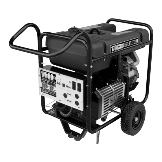
ULTRA SOURCE
Portable Generator
Owner's
Manual
• SAFETY
• ASSEMBLY
• OPERATION
• TROUBLESHOOTING
• ELECTRICAL DATA
• PARTS
COMMERCIAL • INDUSTRIAL • RESIDENTIAL
• WARRANTY
MODEL: 004583-0
17,500 Watt Portable Generator
and 60 amp manual transfer switch
AUTHORIZED DEALER SUPPORT:
with built-in load center
1-800-333-1322
Advertisement
Table of Contents

Subscribe to Our Youtube Channel
Related Manuals for Generac Power Systems Guardian ULTRA SOURCE 004583-0


Summary of Contents for Generac Power Systems Guardian ULTRA SOURCE 004583-0
- Page 1 • SAFETY • ASSEMBLY • OPERATION • TROUBLESHOOTING • ELECTRICAL DATA • PARTS COMMERCIAL • INDUSTRIAL • RESIDENTIAL • WARRANTY MODEL: 004583-0 17,500 Watt Portable Generator and 60 amp manual transfer switch AUTHORIZED DEALER SUPPORT: with built-in load center 1-800-333-1322...
-
Page 2: Table Of Contents
Table of Contents Residential Portable Generator System Safety Rules ...1-3 Section 1 – General Information ...4 Unpacking ...4 1.1.1 Accessory Box...4 Assembly ...4 1.2.1 Assembling the Wheel Kit ...4 1.2.2 Assembling the Handle ...5 1.2.3 Battery Connection ...5 Section 2 – Operation ...6 Know The Generator ...6... -
Page 3: Read This Manual Thoroughly
INTRODUCTION Thank you for purchasing this model of the GUARDIAN line by Generac Power Systems, Inc. This model is a compact, high performance, air-cooled, engine driven generator designed to supply electrical power to operate electrical loads when utility power is unavailable due to a power outage. -
Page 4: General Hazards
Exercise care near running generators. • Never operate in an enclosed area or indoors. • For safety reasons, GENERAC maintenance of this equipment is carried out by a GENERAC Authorized Dealer. • The engine exhaust fumes contain carbon monoxide, which can be DEADLY. -
Page 5: Electrical Hazards
If you have any question pertaining to fire extinguishers, consult your local fire department. IMPORTANT SAFETY INSTRUCTIONS Residential Portable Generator System • Do not smoke around the generator. Wipe up any fuel or oil spills immediately. Ensure that no combustible materials are left on or near the generator, as FIRE or EXPLOSION may result. -
Page 6: Section 1 - General Information
Section 1 – General Information Residential Portable Generator System 1.1 UNPACKING • Set the palleted carton on a rigid flat surface. • Remove staples along bottom of carton that fasten carton to pallet. Open carton from top. • Remove all packaging material. -
Page 7: Battery Connection
• Double check all connections to ensure they are in the correct location and secure. See Figure 3 at right. Section 1 - General Information Residential Portable Generator System Figure 2 - Handle Assembly Figure 3 - Battery Connections Negative... -
Page 8: Section 2 - Operation
Section 2 – Operation Residential Portable Generator System OPERATION 2.1 KNOW THE GENERATOR Read the Owner’s Manual and Safety Rules before operating this generator. Compare the generator to this illustration to become familiarized with the locations of various controls and adjustments. Save this manual for future reference. -
Page 9: Cord Sets And Connector Plugs
For example, a defective appliance can cause a ground fault. Section 2 – Operation Residential Portable Generator System A GFCI receptacle does NOT protect against circuit overloads, short circuits, or shocks. For example, electric shock can still occur if a person touches charged electrical wires while standing on a non-conducting surface, such as a wood floor. -
Page 10: 120/240V Ac, 30 A, Receptacle
Section 2 – Operation Residential Portable Generator System Figure 9 - 120 VAC, 30 Amp Receptacle Use this receptacle to operate 120 Volt AC, 60 Hz, single phase loads requiring up to 3600 watts (3.6 kW) of power at 30 Amps. -
Page 11: How To Use The Generator
Section 2 – Operation Residential Portable Generator System 2.3.2 CONNECTING ELECTRICAL LOADS DO NOT connect 240 Volt loads to 120 Volt receptacles. DO NOT connect 3-phase loads to the generator. DO NOT connect 50 Hz loads to the generator. -
Page 12: Wattage Reference Guide
Section 2 – Operation Residential Portable Generator System 2.5 WATTAGE REFERENCE GUIDE Device ..... . .Running Watts *Air Conditioner (12,000 Btu) ....1700 *Air Conditioner (24,000 Btu) . -
Page 13: Adding Gasoline
30 days or longer. See "Storage" on page 18. Never use engine or carburetor cleaner products in the fuel tank as permanent damage may occur. Residential Portable Generator System 2.7 TO START THE ENGINE ------------- WARNING: Never start or stop engine with electrical devices plugged into the receptacles AND devices turned on. -
Page 14: Stopping The Engine
Section 2 – Operation Residential Portable Generator System • Move engine CHOKE knob to “Full Choke” position. Figure 17 - Full Choke Position • To start engine, press and hold the Start/Run/Stop switch in the “Start” position. The engine will crank and attempt to start. -
Page 15: Charging A Battery
Follow the hydrometer manufacturer's instructions carefully. Generally, a battery is considered to be at 100% state of charge when specific gravity of its fluid (as measured by hydrometer) is 1.260 or higher. Section 2 – Operation Residential Portable Generator System... -
Page 16: Section 3 - Maintenance
Spark Plug Gap Gasoline Capacity Oil Type Oil Capacity Run Time/Fuel Consumption-1/2 Load Daily Every Season ✓ ✓ GPS 17,500 004583-0 17.5 kW 26.2 kW 120/240 72.9 Amps 145.8 Amps 60 Hz @ 3600 RPM Single Phase 12 Volts 10 Amperes 992cc Champion RC14YC or Equivalent 0.040 inch or (1.01 mm) -
Page 17: General Recommendations
Inspect cooling air slots and openings on the generator. These openings must be kept clean and unobstructed. Section 3 — Maintenance Residential Portable Generator System 3.3.3 ENGINE MAINTENANCE DANGER! When working on the generator, always disconnect negative cable from battery. Also disconnect spark plug wires from spark plug and keep wire away from spark plug. -
Page 18: Replacing The Spark Plug
Section 3 — Maintenance Residential Portable Generator System 3.3.6 REPLACING THE SPARK PLUG Use Champion RC14YC spark plug or equivalent. The correct air gap is 1.01 mm (0.040 in.). Replace the plug once each year. This will help your engine start easier and run better. -
Page 19: Adjusting Valve Clearance
NOTE: You must hold the rocker arm jam nut in place as you turn the pivot ball stud. Section 3 — Maintenance Residential Portable Generator System When valve clearance is correct, hold the pivot ball stud in place with the allen wrench and tighten the rocker arm jam nut. Tighten the jam nut to 174 in/lbs. -
Page 20: General
Section 3 — Maintenance Residential Portable Generator System 3.7 GENERAL The generator should be started at least once every seven days and be allowed to run at least 30 minutes. If this cannot be done and you must store the unit for more than 30 days, use the following information as a guide to prepare it for storage. -
Page 21: Section 4 - Troubleshooting
Engine lacks power. Engine “hunts” or falters. No Battery Charge DC output. Section 4 — Troubleshooting Commercial-Industrial-Residential Portable Generator System CAUSE 1. Circuit breaker is open. 2. Poor connection or defective cord set. 3. Connected device is bad. 4. Fault in generator. -
Page 22: Kit Includes
Section 5—Installation for Manual Transfer Switch KIT INCLUDES: 1. Power Inlet Box Pre-wired with the 50 amp male receptacle, this box is located outside the home where the generator will be operated. 2. Pre-wired Manual Transfer Switch and Emergency Load Center with 16 Circuits Installed within 1 foot of the home’s main distribution panel. - Page 23 FIGURE A PLAN THE LOCATION OF YOUR GENERATOR (Fig. A) shows the GUARDIAN Ultra Source 17,5000 watt portable generator placed outside the home and connected to the weather protective external box. The ground rod and ground strap show a suggested location only.
- Page 24 The wires connected to the service main circuit breaker remain live or Black “HOT”. Avoid contact with these wires and the service main circuit breaker connection lugs. WARNING 1 ft Generac Power Systems, Inc.
- Page 25 Manual Transfer Switch is now installed. NOTE: If additional circuits are required to be protected. Generac offers and additional 30A manual transfer switch and 30A Power Inlet Kit (Model 5341). This kit can be ordered direct from the factory 1-800-747-1530 (Option 2).
-
Page 26: Section 6-Operation Of Generator With Manual Transfer Switch
At the other end is the male connector (NEMA 14-50) which plugs into the portable generator’s control panel and is locked in place by the supplied spring retainer. The power inlet box must be locked to ensure safety and to discourage tampering. -
Page 27: Transfer To Generator Power Source When Utility Power Fails
TRANSFER TO GENERATOR POWER SOURCE WHEN UTILITY POWER FAILS Move generator to within approximately 10 feet of the power inlet box. Connect ground strap to the generator’s grounding lug and to the grounding rod. Open the door of the Manual Transfer Switch. Slide the mechanical interlock connecting the 60 Amp and 50 Amp circuit breakers at the top of the panel to turn “Off”... -
Page 28: Manual Transfer Switch
Section 6—Operation of Generator with Manual Transfer Switch INTERCONNECTION DRAWING ULTRASOURCE GENERATOR CONNECTED TO THE EXTERNAL CONNECTION BOX, MANUAL TRANSFER SWITCH AND HOME’S MAIN ELECTRICAL DISTRIBUTION PANEL... -
Page 29: Section 7 - Notes
Section 7 - Notes Residential Portable Generator System... -
Page 30: Section 9 - Electrical Data
Section 8 — Electrical Data Commercial-Industrial-Residential Portable Generator System Wiring Diagram, UltraSource Portable Generator – Drawing No. 0G0731 120V/30A 120V/30A TWISTLOK TWISTLOK WHITE WHITE WHITE WHITE C.B. C.B. C.B. C.B. ENGINE WIRING ENGINE WIRING BLACK BLACK BATTERY BATTERY 120V/20A 120V/20A... - Page 31 ELECTRONIC GOVERNOR / ENGINE SHUTDOWN P.C.B. ENGINE SHUTDOWN P.C.B. VOLTAGE VOLTAGE REGULATOR REGULATOR Commercial-Industrial-Residential Portable Generator System Wiring Diagram, UltraSource Portable Generator – Drawing No. 0G0731 IDLE CONTROL IDLE CONTROL TRANSFORMERS TRANSFORMERS 10A AUTO 10A AUTO RESET BKR RESET BKR...
- Page 32 Section 8 — Electrical Data Commercial-Industrial-Residential Portable Generator System Schematic, UltraSource Portable Generator – Drawing No. 0G0733 BATTERY CHARGE WINDING BATTERY CHARGE WINDING 66A 11S C1-5 C1-5 C1-4 C1-4 C1-3 C1-3 10A BATTERY CHARGE WINDING 10A BATTERY CHARGE WINDING C1-10...
-
Page 33: Section 9 – Electrical Data
CIRCUIT 8 CIRCUIT 8 NEUTRAL NEUTRAL (WHT) (WHT) CIRCUIT 6 CIRCUIT 6 Section 8 — Electrical Data Commercial-Industrial-Residential Portable Generator System Wiring Diagram, Manual Transfer Switch – Drawing No. 0G1065 GROUND BAR GROUND BAR GROUND(GRN)* GROUND(GRN)* GEN2(RED)* GEN2(RED)* GEN1(BLK)* GEN1(BLK)*... -
Page 34: Parts Lists
Section 9 — Exploded Views and Parts Lists Commercial-Industrial-Residential Portable Generator System Manual Transfer Switch with Load Center – Drawing No. 0G0939-B... - Page 35 0E7888E 0E7888F 0G0863 0G0750 0G1494 Section 9 — Exploded Views and Parts Lists Commercial-Industrial-Residential Portable Generator System Manual Transfer Switch with Load Center – Drawing No. 0G0939-B QTY. DESCRIPTION BOX LOAD CENTER W/HARDWARE CIRCUIT BREAKER INTERLOCK CIRCUIT BREAKER 20A 2P...
-
Page 36: Section 9 - Exploded Views And Parts Lists
Section 9 — Exploded Views and Parts Lists Commercial-Industrial-Residential Portable Generator System GT-990 & GT-760 Engine (Page 1) – Drawing No. 0E8589-N... - Page 37 QTY. DESCRIPTION ASSEMBLY, HOUSING COVER WITH SLEEVE SCREW, HHFC M10-1.5 X 55 SCREW HHFC M6-1.0 X 25 HOOK, LIFTING COVER, ROCKER W/OIL FILL "GENERAC" TEXT GASKET, VALVE COVER KEEPER, VALVE SPRING RETAINER, VALVE SPRING SPRING, VALVE SEAL, VALVE STEM D7...
- Page 38 Section 9 — Exploded Views and Parts Lists Commercial-Industrial-Residential Portable Generator System GT-990 & GT-760 Engine (Page 2) – Drawing No. 0E8589-N...
- Page 39 WRAPPER, UPPER CYLINDER 2 0F1177 ASSEMBLY, GROUND WIRE 022097 WASHER LOCK M6-1/4 Section 9 — Exploded Views and Parts Lists Commercial-Industrial-Residential Portable Generator System GT-990 & GT-760 Engine (Page 2) – Drawing No. 0E8589-N ITEM PART NO#. QTY. 092079 0F1338B...
- Page 40 Section 9 — Exploded Views and Parts Lists Commercial-Industrial-Residential Portable Generator System Generator – Drawing No. 0D4488-F...
- Page 41 082121C CLIP-J VINYL COAT .625 ID 066386 ASSEMBLY, BRUSH HOLDER 0C2824 SCREW TAP-R #10-32 X 9/16 Section 9 — Exploded Views and Parts Lists Commercial-Industrial-Residential Portable Generator System Generator – Drawing No. 0D4488-F ITEM PART NO. 0A2038 022237 022511 022131...
- Page 42 Section 9 — Exploded Views and Parts Lists Commercial-Industrial-Residential Portable Generator System Control Panel – Drawing No. 0G0727-B...
- Page 43 022473 WASHER FLAT 1/4 022097 WASHER LOCK M6-1/4 049813 NUT HEX M6-1.0 G8 Section 9 — Exploded Views and Parts Lists Commercial-Industrial-Residential Portable Generator System Control Panel – Drawing No. 0G0727-B ITEM PART NO. QTY. 065795 0D4804 0C1085 051715 022264...
- Page 44 Section 9 — Exploded Views and Parts Lists Commercial-Industrial-Residential Portable Generator System Frame, Handle & Wheel Kit – Drawing No. 0E0695-B...
-
Page 45: Parts Lists
039214 BOLT CARR 3/8-16 X 1 0D9165 AXLE, 3/4"DIA X 30" (15 kW) Section 9 — Exploded Views and Parts Lists Commercial-Industrial-Residential Portable Generator System Frame, Handle & Wheel Kit – Drawing No. 0E0695-B ITEM PART NO. 045900 0D7668 0D4999... -
Page 46: Section 10 - Warranty
Warranties for Generac Power Systems, Inc.," which is enclosed herewith on a separate sheet, also provided to you by Generac. The ECS Warranty applies only to the emission control system of your new engine. If there is any conflict in terms between the ECS Warranty and the Generac Warranty, the ECS warranty shall apply except in circumstances where the Generac Warranty may provide a longer warranty period. -
Page 47: Emission Control System Warranty
(1) Any warranted, emissions-related parts that are not scheduled for replacement as required maintenance in the Owner's Manual shall be warranted for the ECS Warranty Period. If any such part fails during the ECS Warranty Period, it shall be repaired or replaced by Generac according to Subsection (4) below. -
Page 48: Section 10 – Warranty
For a period of two years from the date of original sale, Generac Power Systems, Inc. (Generac) warrants that its Guardian generator and accompanying transfer switch will be free from defects in material and workmanship for the items and period set forth below. Generac will, at its option, repair or replace any part which, upon examination, inspection and testing by Generac or a Guardian Authorized Warranty Service Dealer, is found to be defective.
Need help?
Do you have a question about the Guardian ULTRA SOURCE 004583-0 and is the answer not in the manual?
Questions and answers