Table of Contents
Advertisement
Quick Links
*This manual should remain with the unit.
ONLY QUALIFIED ELECTRICIANS OR CONTRACTORS
SHOULD ATTEMPT INSTALLATION!!
Owner's Manual
Models:
004373-3 (40 kW/Single-phase w/ 200 Amp
004626-2 (40 kW/Single-phase w/ 200 Amp
®
POWER SYSTEMS, INC.
®
DANGER
Liquid-cooled, Prepackaged
Standby Generators
Transfer Switch)
Transfer Switch California
Emissions)
Advertisement
Table of Contents

Related Manuals for Generac Power Systems 004373-3, 004626-2


Summary of Contents for Generac Power Systems 004373-3, 004626-2
- Page 1 POWER SYSTEMS, INC. *This manual should remain with the unit. DANGER ONLY QUALIFIED ELECTRICIANS OR CONTRACTORS SHOULD ATTEMPT INSTALLATION!! Owner’s Manual Liquid-cooled, Prepackaged Models: 004373-3 (40 kW/Single-phase w/ 200 Amp Transfer Switch) 004626-2 (40 kW/Single-phase w/ 200 Amp Transfer Switch California Emissions) ®...
-
Page 2: Introduction
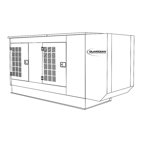
INTRODUCTION Thank you for purchasing the Guardian product line by Generac Power Systems. This model is a compact, high performance, liquid-cooled, engine-driven gen- erator designed to automatically supply electrical power to operate critical loads during a utility power failure. This unit is factory installed in an all-weather, metal enclosure that is intended exclusively for outdoor installation. -
Page 3: Table Of Contents
4.11.2 Return to Service...18 4.12 Service Schedule ...19 Section 5 – Troubleshooting ...20 Section 6 – Electrical Data ...21 Section 7 – Exploded Views and Parts Lists ...30 Section 8 – Notes ...59 Section 9 – Warranty ...60 Generac ® Power Systems, Inc. -
Page 4: General Hazards
Generac ® Power Systems, Inc. GENERAL HAZARDS • For safety reasons, Generac recommends that the installation, initial start-up and maintenance of this equipment is carried out by a Generac/Guardian Authorized Dealer. • Installation, operation, servicing and repair of this (and related) equipment must always comply with applicable codes, standards, laws and regulations. -
Page 5: Electrical Hazards
FIRE or EXPLOSION may result. Keep the area surrounding the generator clean and free from debris. • Generac generator sets may operate using one of sev- eral types of fuels. All fuel types are potentially FLAM- MABLE and/orEXPLOSIVE and should be handled with care. -
Page 6: Section 1 - General Information Guardian Liquid-Cooled 40 Kw Generator
Each single winding can supply a 120-volt, 60-Hertz AC output. Generac ® Power Systems, Inc. When the two windings are connected in series, a 240- volt, 60-Hertz AC output results. -
Page 7: Main Circuit Breaker
Always remove this fuse before commencing work on the generator. The unit will not start or crank if the fuse is blown. Replace the fuse with one of the same size, type, and rating. Generac uses an AGC fuse rated at 15 amps. SPECIFICATIONS 1.8.1 GENERATOR... -
Page 8: Generator And Load Compatibility
Fuel Consumption Natural Gas 004373-3 & 004626-2 ...720 cfh LP Gas 004373-3 & 004626-2 ...288 cfh/7.9gph Generac ® Power Systems, Inc. FUEL REQUIREMENTS AND RECOMMENDATIONS With LP gas, use only the vapor withdrawal system. This type of system uses the vapors formed above the liquid fuel in the storage tank. -
Page 9: Engine Oil Recommendations
Using any high sili- cate antifreeze boosters or additives also will cause overheating. Generac also recommends that any soluble oil inhibitor NOT be used for this equipment. Section 1 — General Information Guardian Liquid-cooled 40 kW Generator 1.12 EMISSIONS CONTROL SYSTEM... -
Page 10: Section 2 - Installation Guardian Liquid-Cooled 40 Kw Generator
Connecting this generator to an electrical system normally supplied by an electric utility shall be by means of a transfer switch (such as the Generac “GTS” type transfer switch), so as to isolate the electric system from the utility distribution system when the generator is operating. Failure to isolate the electric system by these means will result in damage to the generator and may also result in injury or death to utility workers due to backfeed of electrical energy. -
Page 11: Emergency Circuit Isolation Method
Figure 2.2 – Generator Grounding Lug (typical) GENERATOR AC NEUTRAL CONNECTIONS Generac uses an UNGROUNDED AC neutral. Grounding is recommended only at the main service entrance. TRANSFER SWITCH START SIGNAL CONNECTIONS 2.6.1 PRE-PACKAGED TYPE SWITCH... -
Page 12: Battery Installation
The battery represents a risk of high short circuit current. When working on the battery, always remove watches, rings or other metal objects, and only use tools that have insulated handles. 10 Generac ® Power Systems, Inc. 2.7.1 VENTED BATTERIES The electrolyte is a dilute sulfuric acid that is harmful to the skin and eyes. -
Page 13: Prior To Initial Start-Up
On acoustic units, cap plugs also are needed to stay within noise specification limits. permitted. Section 2 — Installation Figure 2.3 - Base Frame Cap Plugs Generac ® Power Systems, Inc. 11... -
Page 14: Section 3 - Operation Guardian Liquid-Cooled 40 Kw Generator
This indicates the time the engine-generator has operat- ed, in hours and tenths of hours. Use the hourmeter along with the periodic maintenance schedule for your generator set. 12 Generac ® Power Systems, Inc. 3.1.6 AUTO/OFF/MANUAL SWITCH See Section 3.2. -
Page 15: Off" Position
• The timer will run for about one minute, and the generator will then shut down. ENGINE HEATER This Generac standby generator comes equipped with a block heater (Figure 3.2, page 14) that is similar to the block heaters used in automotive applications. -
Page 16: Weekly Exercise Cycle
• The generator is now programmed to start and exer- cise every seven days thereafter, on the day and at the time of day the switch was activated. 14 Generac ® Power Systems, Inc. • Place a sign on the generator’s control panel and on the transfer switch that indicates the day and time the generator will be exercising. -
Page 17: Changing The Engine Oil And Filter
8. Check the oil level after checking for leaks to ensure that the oil is filled to the proper level. To replace the engine air cleaner, (Generac part num- ber 0A4637, simply remove the air cleaner cover and replace the air filter making sure it is positioned properly before reattaching the cover. -
Page 18: Spark Plugs
Power Systems, Inc. Air Cleaner 4.5.1 BATTERY REPLACEMENT Generac uses a Group 27F vented type battery that has 600 CCA @ 0º F . Generac’s part number is 058665. The BCI number should be located directly on the battery. DANGER... -
Page 19: Cooling System
Once each year, have the generator cleaned and inspect- ed by a Generac/Guardian Authorized Dealer. Service technicians will use dry, low pressure air to clean inter- nal windings. Parts inside the control console should be cleaned and inspected at this time as well. -
Page 20: Out Of Service Procedure
8. Remove the battery and store it in a cool, dry room on a wooden board. Never store the battery on any concrete or earthen floor. 9. Clean and wipe the entire generator. 18 Generac ® Power Systems, Inc. 4.11.2 RETURN TO SERVICE... -
Page 21: Service Schedule
4.12 SERVICE SCHEDULE ATTENTION: It is recommended that all service work be performed by your nearest Generac/Guardian Authorized Dealer. SYSTEM/COMPONENT X = Action R = Replace/Adjust as Needed * = Notify Dealer if Repair is Needed. FUEL Fuel lines and connections*... -
Page 22: Section 5 - Troubleshooting Guardian Liquid-Cooled 40 Kw Generator
There is no AC output from the generator. There is no transfer to standby after utility source failure. *Contact your nearest Generac/Guardian Authorized Dealer for assistance. 20 Generac ® Power Systems, Inc. CAUSE 1. Fuse blown 2. Loose, corroded or defective battery cables 3. -
Page 23: Section 6 - Electrical Data
UNIT: 729.7 kg [1609 lbs] STEEL COMPARTMENT: 208.6 kg [460 lbs] UNITS: mm [INCHES] 965 [37.99"] 1160 [45.67"] 877 [34.51"] REAR VIEW (1) 12V BATTERY SEE NOTE 4 GRAVITY 981 [38.62"] 1930 [75.98"] RIGHT SIDE VIEW Generac ® Power Systems, Inc. 21... - Page 24 (Model Nos. 004373-3 & 004626-2) Guardian Liquid-cooled 40 kW Generator Wiring Diagram (4.3L) – Drawing No. 0A4591-B BLACK GREEN BLACK OPTIONAL 22 Generac ® Power Systems, Inc. 85 WIRE USED ON A&B OPTION PANELS ONLY 86 WIRE USED ON "C" OPTION PANELS ONLY BLACK...
- Page 25 Section 6 — Electrical Data (Model Nos. 004373-3 & 004626-2) Guardian Liquid-cooled 40 kW Generator Schematic (4.3L) – Drawing No. 0A4592-B Generac ® Power Systems, Inc. 23...
- Page 26 (Model No. 004373-3) Guardian Liquid-cooled 40 kW Generator Electrical Schematic (Stepper Motor) – Drawing No. 0A5858 BLACK P/N 98647 LEGEND GCB - GOVERNOR CONTROL BOARD HZ - FREQUENCY METER TB1 - TERMINAL BLOCKS 24 Generac ® Power Systems, Inc. BLUE BLUE...
- Page 27 (Model No. 004373-3) Guardian Liquid-cooled 40 kW Generator Wiring Diagram — Pre-pack Panel (4.3L) – Drawing No. 0D4992-A ACTUATOR GOVERNOR Section 6 — Electrical Data Generac 225A BLACK ® Power Systems, Inc. 25...
- Page 28 Section 6 — Electrical Data (Model No. 004373-3) Guardian Liquid-cooled 40 kW Generator Electrical Schematic — Pre-pack Panel (4.3L) – Drawing No. 0D4993-A YELLOW ORANGE YELLOW BROWN BLACK (CONNECTOR ENGINE (CONNECTOR PANEL LOWER 26 Generac ® Power Systems, Inc.
- Page 29 Section 6 — Electrical Data (Model Nos. 004373-3 & 004626-2) Guardian Liquid-cooled 40 kW Generator Wiring Diagram/Schematic – Lower Panel – Drawing No. 0D5997 (CONNECTOR PANEL CONTROL Generac ® Power Systems, Inc. 27...
- Page 30 Section 6 — Electrical Data (Model No. 004626-2) Guardian Liquid-cooled 40 kW Generators Wiring Diagram - Control Panel - Drawing No. 0D6974 SHIELD MPU- MPU+ ACT- ACT+ BAT- BAT+ 28 Generac ® Power Systems, Inc. 225A BLACK...
- Page 31 (Model No. 004626-2) Guardian Liquid-cooled 40 kW Generators Electrical Schematic - Control Panel - Drawing No. 0D6975 (CONNECTOR ENGINE Section 6 — Electrical Data YELLOW SHIELD MPU- MPU+ ACT- ACT+ (CONNECTOR PANEL LOWER Generac ® Power Systems, Inc. 29...
-
Page 32: Section 7 - Exploded Views And Parts Lists (Model Nos. 004373-3 & 004626-2) Guardian Liquid-Cooled 40 Kw Generators Base - Drawing No. 0C4399-D
Section 7 — Exploded Views and Parts Lists (Model Nos. 004373-3 & 004626-2) Guardian Liquid-cooled 40 kW Generators Base - Drawing No. 0C4399-D 30 Generac ® Power Systems, Inc. - Page 33 WASHER FLAT .281 ID X 1.0 OD SCREW TH-FRM M6-1 X 16 N WA Z/JS PLUG 3/4 BUTTON SCREW HHC 1/4-20 X 1 G5 WASHER FLAT 1/4 ZINC WASHER LOCK M6-1/4 NUT HEX 1/4-20 STEEL Generac ® Power Systems, Inc. 31...
- Page 34 Section 7 — Exploded Views and Parts Lists (Model Nos. 004373-3 & 004626-2) Guardian Liquid-cooled 40 kW Generators Compartment - Drawing No. 0D8992 32 Generac ® Power Systems, Inc. BASE FRAME...
- Page 35 SCREW HHC M8-1.25 X 16 G8.8 WASHER FLAT M6-1/4 ZINC WASHER LOCK M6-1/4 NUT HEX 1/4-20 STEEL GASKET DOOR RUBBER SCREW SHOULDER COVER EXHAUST HOLE FASTENER RATCHET STRIP SEALANT 1/8 X 1 WASHER FLAT 5/16 ZINC Generac ® Power Systems, Inc. 33...
- Page 36 (Model No. 004373-3) Guardian Liquid-cooled 40 kW Generator Control Panel 4.3L – Drawing No. 0D4995-C 18 49 50 54 55 56 57 18 49 50 VIEW A-A 34 Generac ® Power Systems, Inc. 55 56 57 ENGINE DOES START, IT WILL SHUT OFF AUTOMATICALLY WITHIN 2 MIN.
- Page 37 NUT HEX #6-32 STEEL 036908 SCREW PPHM #6-32 X 1-1/4 0C2428 SCREW PHTT #6-32 X 1/2 ZYC 0C2323 SCREW PHTT #6-32 X 5/8 ZYC 0D5324 FUSE & HOLDER LITTEL 7.5A 0A9611 REF. FUSE 7.5AXBK/AGC7.5NX W/22670 Generac ® Power Systems, Inc. 35...
- Page 38 Section 7 — Exploded Views and Parts Lists (Model No. 004626-2) Guardian Liquid-cooled 40 kW Generator Control Panel – Drawing No. 0D6978-A PANEL FACE 36 Generac ® Power Systems, Inc. 53 54 55 56 44 45 46 47 53 54 55 56...
- Page 39 SCREW PHTT #6-32 X 1/2 ZYC 0C2323 SCREW PHTT #6-32 X 5/8 ZYC 0A2284 SCREW SWAGE 8-32 X 1/2 Z/YC 0C1127 DECAL AVR COVER 0D5324 FUSE & HOLDER LITTEL 7.5A 0A9611 FUSE 7.5AXBK/AGC7.5NX W/22670 Generac ® Power Systems, Inc. 37...
- Page 40 RECOMMENDED TERMINAL TIGHTENING TORQUES FOR CIRCUIT BREAKER AND NEUTRAL BLOCK ITEM DESCRIPTION CIRCUIT BREAKER LINE SIDE CIRCUIT BREAKER LOAD SIDE NEUTRAL BLOCK 38 Generac ® Power Systems, Inc. BOTTOM OF CONTROL PANEL REF. 60 0 RING TERMINALS FASTEN COMPRESSION FROM ALTERNATOR...
- Page 41 NEUTRAL BLOCK 390/200-400A JUNCTION BLOCK 3/8-16 WASHER LOCK #10 SCREW PHM #10-32 X 5/8 CAD WASHER LOCK 3/8 NUT HEX 3/8-16 STEEL WASHER FLAT 5/16 ZINC WASHER LOCK M8-5/16 NUT HEX M8-1.25 G8 YEL CHR Generac ® Power Systems, Inc. 39...
- Page 42 Section 7 — Exploded Views and Parts Lists (Model Nos. 004373-3 & 004626-2) Guardian Liquid-cooled 40 kW Generators Generator – Drawing No. 0D9490 40 Generac ® Power Systems, Inc.
- Page 43 SHROUD ALTERNATOR SHEET METAL SCREEN SHROUD SAE BRACKET TENSIONER SAE SCROLL TRIM VINYL BLACK 1/8 GP WASHER LOCK M6-1/4 SCREW HHC M6-1.0 X 25 G8.8 SCREW HHC M6-1.0 X 16 G8.8 SCREW SWAGE 1/4-20 X 1/2 Z/YC Generac ® Power Systems, Inc. 41...
- Page 44 Section 7 — Exploded Views and Parts Lists (Model Nos. 004373-3 & 004626-2) Guardian Liquid-cooled 40 kW Generators Engine – Drawing No. 0D6980-A 42 Generac ® Power Systems, Inc.
- Page 45 NUT HEX 3/8-16 STEEL CONNECTOR C/C VENT PIN DOWEL M10 X 24 SCREW HHC 3/8-16 X 3-1/2 G5 PLATE FLEX GM CASTING ADAPTOR SENSOR COOLANT LEVEL ASSY MAGPICKUP (3/8-24 MALE) (MODEL 004626 0NLY) THERMOSTAT 195 DEG Generac ® Power Systems, Inc. 43...
- Page 46 Section 7 — Exploded Views and Parts Lists (Model Nos. 004373-3 & 004626-2) Guardian Liquid-cooled 40 kW Generators Engine – Drawing No. 0A4304-L 44 Generac ® Power Systems, Inc.
- Page 47 WASHER FLAT HEAVY DUTY WASHER LOCK M10 SCREW HHC M10-1.5 X 25 G8.8 BOLT TENSIONER PULLEY NUT HEX M10-1.5 G8 YEL CHR SPARK PLUG 5.7L GM WASHER FLAT M12 CLAMP VINYL 1.06 X .406 Z FILTER OIL Generac ® Power Systems, Inc. 45...
- Page 48 042568 077043E 15 ** 077043A 077043A * USED ON "R" VOLTAGE GENERATORS ONLY ** NOT SHOWN 46 Generac ® Power Systems, Inc. TO THERMOSTAT HOUSING DESCRIPTION BARBED ELBOW 90 3/8 NPT X 5/8 CLAMP VINYL 1.06 X .406 Z (MOUNTED TO ALTERNATOR TO HOLD # 5 IN PLACE) CLAMP HOSE #8 .53 - 1.00...
- Page 49 CABLE BATTERY RED #1 X 31.00 SCREW HHC M8-1.25 X 60 FTHD NUT LOCK M8 NUT LOCK HEX M8-1.25 (NYLON INSERT) SCREW HHC 3/8-16 X 3/4 G5 WASHER FLAT M10-3/8 ZINC WASHER SHAKEPROOF EXT 7/16 STL WASHER LOCK 3/8 Generac ® Power Systems, Inc. 47...
- Page 50 Section 7 — Exploded Views and Parts Lists (Model Nos. 004373-3 & 004626-2) Guardian Liquid-cooled 40 kW Generators 4.3L Radiator – Drawing No. 0D7992-C 48 Generac ® Power Systems, Inc.
- Page 51 SCREW HHC 1/4-20 X 1 G5 WASHER LOCK M6-1/4 WASHER FLAT 1/4 ZINC SCREEN FRONT SCREW HHTT 1/4-20 X 1 CZ WASHER LOCK M6-1/4 WASHER FLAT 1/4 ZINC CAP RADIATOR 13 PSI-FOR SERVICE ONLY Generac ® Power Systems, Inc. 49...
- Page 52 TUBE, CROSS OVER 0E0698 TUBE, 90 ELBOW 0C4170 BRACKET EXHAUST SHIELD 0C4305 SHIELD A-GRP HEAT 0C2454 SCREW TH-FRM M6-1 X 16 N WA Z/JS 50 Generac ® Power Systems, Inc. COMPARTMENT FRONT ITEM PART NO. QTY. DESCRIPTION 0C3433A CLAMP BAND 2.5"...
- Page 53 4.3L Air Cleaner – Drawing No. 0E0712 DESCRIPTION NUT WING 1/4-20 NYLK PLATE AIR CLEANER TOP FILTER AIR 11.5" CA326 PLATE,AIR CLEANR BOT STUD TH 1/4-20 X 3 G2 ZNC FULL NUT HEX 1/4-20 STEEL GROMMET CONNECTOR C/C VENT Generac ® Power Systems, Inc. 51...
- Page 54 Section 7 — Exploded Views and Parts Lists (Model No. 004373-3) Guardian Liquid-cooled 40 kW Generators 4.3L Nat. Gas Fuel System – Drawing No. 0E0714 52 Generac ® Power Systems, Inc.
- Page 55 ADAPTOR CARBURETOR W/INLET GASKET CARBURETOR ADAPTOR BARBED ELBOW 90 DEG 1/8 NPT X 3/8 VALVE PCV HOSE 3/8 ID SINGLE BRAID (10") NUT HEX 1/4-28 STEEL WASHER LOCK M6-1/4 ARM THROTTLE-REWORK BALL JOINT PLA .25-28 Generac ® Power Systems, Inc. 53...
- Page 56 Section 7 — Exploded Views and Parts Lists (Model No. 004626-2) Guardian Liquid-cooled 40 kW Generators 4.3L Nat. Gas Fuel System – Drawing No. 0E1338 TO INTAKE MANIFOLD VALVE COVER 54 Generac ® Power Systems, Inc. ATTACH TO FAN SCROLL ASSEMBLY P/N 0D3509...
- Page 57 GASKET CARBURETOR ADAPTOR ASSY THROTTLE PF42 WIRE CONN WASHER LOCK #10 SCREW SHC #10-32 X 5/8 G8.8 NZ GASKET CARB IMPCO 225 SCREW PHM SEMS #12-24 X 5/8 EX NUT HEX 5/16-18 STEEL SADDLE 1-3/8 Generac ® Power Systems, Inc. 55...
- Page 58 Section 7 — Exploded Views and Parts Lists (Model No. 004626-2) Guardian Liquid-cooled 40 kW Generators Exhaust – Drawing No. 0E1347 56 Generac ® Power Systems, Inc.
- Page 59 WASHER LOCK #8-M4 WASHER FLAT #8 ZINC SCREW PPHM #8-32 X 1/2 WASHER FLAT M6 WASHER LOCK M6-1/4 NUT HEX M6 X 1.0 G8 YEL CHR DECAL IMPORTANT EXHAUST EMISSION INFO WASHER FLAT 3/8-M10 ZINC Generac ® Power Systems, Inc. 57...
- Page 60 022097 064526 029333A 074031 051716 049226 076040 098647 036409 0C2184 58 Generac ® Power Systems, Inc. DESCRIPTION ASSEMBLY MOTOR STEPPER BRACKET GOVERNOR MOUNTING CONNECTOR INTERFACE ASSEMBLY LEVER STEPPER MOTOR BALL JOINT 1/4-28 NUT HEX 1/4-28 STEEL SCREW HHC M6-1.0 X 10 G8.8...
-
Page 61: Section 8 - Notes
Section 8 – Notes Guardian Liquid-cooled 40 kW Generators Generac ® Power Systems, Inc. 59... -
Page 62: Section 9 - Warranty Guardian Liquid-Cooled 40 Kw Generators
Owner’s Manual. For warranty purposes, Generac recommends that you retain all receipts covering maintenance on your engine. However, Generac cannot deny warranty solely due to the lack of receipts or for your failure to ensure the completion of all scheduled maintenance. -
Page 63: Emission Control System Warranty
Such use voids this ECS Warranty and shall be sufficient grounds for disallowing an ECS Warranty claim. Generac shall not be held liable hereunder for failures of any warranted parts of a Generac engine caused by the use of such an unapproved, add-on, modified, counterfeit and/or “grey market”... -
Page 64: Warranty Schedule
"PREPACKAGED EMERGENCY AUTOMATIC STANDBY GENERATORS" For a period of two years Generac Power Systems, Inc. (Generac) will, at its option, repair or replace any part which, upon examination, inspection and testing by Generac or a Generac Authorized Warranty Service Dealer, is found to be defective under normal use and service, in accordance with the warranty schedule set forth below.
Need help?
Do you have a question about the 004373-3, 004626-2 and is the answer not in the manual?
Questions and answers