Table of Contents
Advertisement
Quick Links
~
I.
RII
. It
..
~
..,
<f.
~
II'
-t
-
o
q
" LP ",,'
OPERATORS MANUAL
FOR THE
44A FOUR - 35C THREE
AND THE
448 FOUR -350 THREE
MARINE DIESEL ENGINES
PUBLICATION NO. 44180
2nd Edition
I
October 2001
WESTERBEKE CORPORA TION • 150 JOHN HANCOCK ROAD
MYLES STANDISH INDUSTRIAL PARK· TAUNTON
MA
02780
WEBSITE: WWW.WESTERBEKE.COM
AII'Il
M.mber Nali01llll MIlI'iM M(IIIufOClu,..,.. Ar.ociDlion
Advertisement
Table of Contents
Troubleshooting

Related Manuals for Westerbeke 44A FOUR-35 C THREE


Summary of Contents for Westerbeke 44A FOUR-35 C THREE
- Page 1 44A FOUR - 35C THREE AND THE 448 FOUR -350 THREE MARINE DIESEL ENGINES PUBLICATION NO. 44180 2nd Edition October 2001 WESTERBEKE CORPORA TION • 150 JOHN HANCOCK ROAD MYLES STANDISH INDUSTRIAL PARK· TAUNTON 02780 WEBSITE: WWW.WESTERBEKE.COM AII'Il M.mber Nali01llll MIlI'iM M(IIIufOClu,..,.. Ar.ociDlion...
- Page 2 CALIFORNIA PROPOSITION 65 WARNING Diesel engine exhaust and some of its constituents are known to the State of California to cause cancer, birth defects, and other reproductive harm. WARNING Exhaust gasses contain Carbon Monoxide, an odorless and colorless gas. Carbon Monoxide is poisonous and can cause unconsciousness and death.
- Page 3 SAFETY INSTRUCTIONS INTRODUCTION PREVENT BURNS - FIRE Read this safety manual carefully. Most accidents are WARNING: caused by failure to follow fundamental rules and precau- Fire can cause injury or death! tions. Know when dangerous conditions exist and take the necessary precautions to protect yourself, your personnel, •...
- Page 4 SAFETY INSTRUCTIONS ACCIDENTAL STARTING TOXIC EXHAUST GASES WARNING: Accidental starting can cause injury WARNING: Carbon monoxide (CO) is deadly gas! death! • Ensure that the exhaust system is adequate to expel gases • Disconnect the battery cables before servicing the engine/ discharged from the engine.
- Page 5 SAFETY INSTRUCTIONS ABYC, NFPA AND USCG PUBLICATIONS FOR • Do not wear loose clothing or jewelry when servicing equipment; tie back long hair and avoid wearing loose INSTALLING DIESEL ENGINES jackets, shirts, sleeves, rings, necklaces or bracelets that Read the following ABYC, NFPA and USCG publications could be caught in moving parts.
- Page 6 INSTALLATION When installing WESTERBEKE engines and generators it is important that strict attention be paid to the following information: CODES AND REGULATIONS Strict federal regulations, ABYC guidelines, and safety codes must be complied with when installing engines and generators in a marine environment.
-
Page 7: Table Of Contents
TABLE OF CONTENTS Parts Identification ..........Water Heater ............. Introduction ............DC Electrical System ........Warranty Procedures ........3 Alternator Troubleshooting ......25 Serial Number Location ....... .4 Battery ............26 Wiring Diagrams/Schematics ...... 27 Control Panels ............. Engine Troubleshooting ........Admirals Panel .......... -
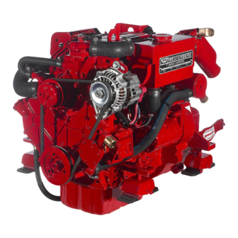
Page 8: Parts Identification
PARTS IDENTIFICATION 44A FOUR/35C THREE COOLANT PRESSURE CAP WATER INJECTED EXHAUST ELBOW THERMOSTAT ASSEMBLY 20ACIRCUIT BREAKER WATER HEATER CONNECTION REAR FRONT SIDE OIL FILL ZINC ANODE OIL FILTER OIL COOLER RIGHT SIDE AIR INTAKE/AIR FILTER OIL FILL FRONT PREHEAT SOLENOID DC ALTERNATOR FUEL FILTER RAW WATER PUMP... -
Page 9: Introduction
INTRODUCTION This WESTERBEKE Diesel Engine is a product of PRODUCT SOFTWARE WESTERBEKE's long years of experience and advanced Product software, (technical data, parts lists, manuals, technology. We take great pride in the superior durability and brochures and catalogs), provided from sources other than dependable performance of our engines and generators. -
Page 10: Serial Number Location
(see the seeking technical information and/or ordering repair parts. separately furnished Parts List). Insist upon WESTERBEKE packaged parts because will fit or generic parts are frequently C2¥ii4il :143i not made to the same specifications as original equipment. -
Page 11: Control Panels
ADMIRAL CONTROL PANEL DESCRIPTION When the engine is shut down with the key switch turned off, the water temperature gauge will continue to register the last This manually-operated control panel is equipped with a temperature reading indicated by the gauge before electrical KEY switch and RPM gauge with an ELAPSED TIME power was turned off The oil pressure gauge will fall to zero meter which measures the engine's running time in hours and... -
Page 12: Captains Panel
CAPTAIN CONTROL PANEL DESCRIPTION The panel also includes an alarm buzzer for low OIL PRESSURE or high COOLANT lEMPERATURE. The This manually-operated control panel is equipped with a RPM gauge is illuminated when the KEY switch is turned on KEY switch, an RPM gauge, PREHEAT and START but- and remains illuminated while the engine is in operation. -
Page 13: Diesel Fuel, Engine Oil And Engine Coolant
A coolant recovery tank kit is supplied with each SAE 20, 10W-30 or 15W-40 41° - 68°F (5 - 20°C) WESTERBEKE diesel engine. The purpose of this recovery SAE 10W-30 or 15W-40 Below 41°F (5°C) tank is to allow for engine coolant expansion and contraction during engine operation, without the loss of coolant and without introducing air into the cooling system. -
Page 14: Preparations For Initial Start-Up
PREPARATIONS FOR INITIAL START-UP PREST ART INSPECTION Before starting your engine for the first time or after a pro- longed layoff, check the following items: Check the engine oil level. Add oil to maintain the level PLASTIC RECOVERY TANK at the high mark on the dipstick. Turn on the fuel supply, then check the fuel supply and examine the fuel filter/water separator bowl for contami- nants. -
Page 15: Starting/Stopping Procedure
STARTING/STOPPING PROCEDURE THE STARTING SYSTEM 5. Should the engine not start when the START button is depressed for 10 to 20 seconds, release both buttons and The 44N35Cdiesel engine has a 12V DC electric starter. wait 30 seconds; repeat the procedure above and preheat The start circuitry is designed so that the PREHEAT button longer. -
Page 16: Warning Lights, Alarms And Circuit Breaker
WARNING LIGHTS, ALARMS & CIRCUIT BREAKER LOW OIL PRESSURE ALARM SWITCH ALTERNATOR WARNINGS ' A low oil pressure alarm switch is located off the engine's The Captain Control Panel indicates alternator low discharge with a red warning light. oil gallery. This switch's sensor monitors the engine's oil pressure. -
Page 17: Engine Break-In Procedure
ENGINE BREAK-IN PROCEDURE DESCRIPTION 3. While using the vessel, run the engine at various engine speeds for the first 25 hours. Avoid prolonged periods of Although your engine has experienced a minimum of one idling. hour of test operations at the factory to make sure accurate cold 4. -
Page 18: The Daily Operation
THE DAILY OPERATION CHECK LIST STARTING THE ENGINE Follow this check list each day before starting your engine. NOTE: See STARTING/STOPPING PROCEDURE in this manual for more detailed instructions. Record the hounneter reading in your log (engine hours relate to the maintenance schedule.) 1. -
Page 19: Maintenance Schedule
MAINTENANCE SCHEDULE In order to use this Maintenance Schedule, it will be neces- WARNING: Never attempt to perform any service sary to log your engine hours. Use your engine hourrneter or record your engine hours by running time. while the engine is running. Wear the proper safety NOTE: equipment such as goggles and gloves, and use the Many of the following maintenance procedures are... - Page 20 Lubricate Panel Key Switch At first 100 hours. then each year at winterizing. with "Lockeze" Transmission Initial fluid change at 25 hours. then every 300 hours or at winterizing. Fluid *WESTERBEKE recommends this service be performed by an authorized mechanic. Engines & Generators...
-
Page 21: Cooling System
When the engine is started cold, external coolant flow is pre- vented by the closed thermostat (although some coolant flow Westerbeke marine diesel engines are designed and equipped is bypassed around the thermostat to prevent the exhaust for fresh water cooling. Heat produced in the engine by com- manifold from overheating). -
Page 22: Thermostat
NOTE: Should a failure occur with the pump:r internal parts (seals bearings), it may be more cost efficient to pur- chase a new pump and rebuild the original pump as a spare. WESTERBEKE -.¥' Engines & Generators Revised: February 2002... -
Page 23: Heat Exchanger
COOLING SYSTEM Changing the Raw Water Pump Impeller NOTE: Also follow the above procedure after having run hard aground. Close the raw water intake valve. Remove the pump cover and, with the aid of two small screwdrivers, carefully pry the If the engine temperature gauge ever shows a higher than impeller out of the pump. -
Page 24: Air Intake/Silencer
COOLING SYSTEM Zinc Anode If the zinc anodes need replacement, hold the hex boss into which the zinc anode is threaded with a wrench while loos- ~ zi~c ~o~e, pencil, is located in the raw water cooling ening the anode with another wrench. This prevents the hex CIrCUIt wIthin the heat exchanger. -
Page 25: Fuel System
FUEL SYSTEM FUEL FILTERS DIESEL FUEL Use No.2 diesel fuel with a cetane rating of 45 or higher. Do The fuel injection pump and the fuel injectors are precisely not use kerosene or home heating fuel. manufactured and they must receive clean diesel fuel, free from water and To ensure this flow of clean fuel, the fuel dirt. -
Page 26: Clow Plugs
GLOW PLUGS DESCRIPTION Re-install the plugs in the engine and test them again. The plugs should get very hot (at the terminal end) within 7 to 15 The glow plugs are wired through the preheat solenoid. seconds. If the plugs don't heat up quickly, check for a short When PREHEAT is pressed at the control panel this solenoid circuit. -
Page 27: Engine Lubricating Oil
ENGINE LUBRICATING OIL LUBRICATION DIAGRAM 2. Replacing the Filter. When removing the used oil fil- ter, you may find it helpful and cleaner to punch a hole in the upper and lower portion of the old filter to drain the OIL PRESSURE oil from it into a container before removing it. -
Page 28: Oil Pressure
OIL PRESSURE OIL PRESSURE TESTING OIL PRESSURE The engine's oil pressure, during operation, is indicated The lubricating system is a pressure feeding system using by the oil pressure gauge on the instrument panel. During an oil pump. The engine oil is drawn from the oil sump by normal operation, the oil pressure will range between 40 and the oil pump, which drives the oil, under pressure, through 60 psi (2.8 and 4.2 kglcm... -
Page 29: Remote Oil Filter
Contact your WESTERBEKE dealer for more information. engine room bulkhead. NOTE: Westerbeke is not responsible for engine failure due to NOTE: Refer to ENGINE OIL CHANGE in this manualfor incorrect installation of the Remote Oil Filter. -
Page 30: Water Heater
WATER HEATER WATER HEATER INSTALLATIONS The pressure cap on the engine's manifold should be aft~r installed the engine's cooling system is filled with This engine is equipped with connections for the plumbing of coolant. Finish filling the cooling system from the remote engine coolant to transfer heat to an on-board water heater. -
Page 31: Dc Electrical System
DC ELECTRICAL SYSTEM ALTERNATOR 1. Start the engine. 2. After the engine has run for a few minutes, measure the The charging system consists of a DC belt driven alternator starting battery voltage at the battery terminals using a with a voltage regulator, an engine DC wiring harness, a multimeter set on DC volts. -
Page 32: Battery
DC ELECTRICAL SYSTEM 7. Now check the voltage between the alternator output ter- Checking the Service Battery minal (B+) and ground. If the circuit is good, the voltage at Check the voltage of the service battery. This battery should the alternator will be the same as the battery, or if an isola- have a voltage between 13 and 14 volts when the engine is tor is in the circuit the alternator voltage will be zero. -
Page 33: Wiring Diagrams/Schematics
MARINE ENGINE WIRING DIAGRAM #39144 SEE NOTE ...I LIFT PUMPS : ::r----------------...I NOTE: An on-off switch should be installed in this circuit to disconnect the starter from the battery in P2~' an emergency and when leaving the boat. Twelve volt engine starters ADMIRAL typically draw 200 to 300 ALARM... - Page 34 MARINE ENGINE WIRING SCHEMATIC #39144 START NOTES: 12 VDC SOL. SURfER r--, THIS PRODUCT IS PRQTI:.CTED BY A MANUAL RESET CIRCUIT BREAKER LOCATED NEAR THE ~------~~r71------~Mr-------------. STARTER ExCESSIVE CURRENT WilL CAUSE THE BREAKER TO TRIP AND THE ENGINE Will SHUT DCWN. THE BUILDER/OWNER MUST BE SURE THAT THE INSTRUMENT PANEL.
- Page 35 MARINE ENGINE WIRING SCHEMATIC #200360 [CATALINA YACHTS] STARTER 12 VDC SOLENOID STARTER r - - -, L _ _ _ J PREHEAT SOLENOID GLOWPLUGS r - - - , ALTERNATOR OUTPUT <+- r:> 10...' < 11: r --, <C r--------Jv· "...
- Page 36 r---- ~~I I~I.,~ "" < I-I..J -< ..110 WHT TO THE START SWITCH 114 GRH :a:- TO THE TACHOMETER GROUND ;!:i 110 RED TO THE 'B' TERM. OF KEYSWITCH :Pi 11:1 114 PUR TO THE'S' TERM. OF KEYSWITCH CA)~; 114 VEL TO THE '5' TERM.
-
Page 37: Engine Troubleshooting
ENGINE TROUBLESHOOTING The following troubleshooting table describes certain problems NOTE: The engine electrical system is protected by a 20 relating to engine service, the probable causes of these prob- ampere manual reset circuit breaker located on a bracket at lems, and the recommendations to overcome these problems. the back of the engine. - Page 38 2. Remove the wire attached to the sender terminal at the terminals), the ground side will not necessarily be connected sender and connect it to ground. See if the gauge reads to the block. full scale, which is the normal reading for this situation. WESTERBEKE Engines & Generators...
-
Page 39: Tachometer
TACHOMETER TACHOMETER/HOUR METER NOTE: Current model tachometers use a coarse adjustment dial to set the tachometer to the crankshaft pulley rpms. The The tachometerlhour meter used in propulsion engine instru- calibrating screw is then used for fine tuning. ment panels contains two separate electrical circuits with a common ground. -
Page 40: Engine Adjustments
ENGINE ADJUSTMENTS ADJUSTING THE IDLE SPEED DRIVE BELT ADJUSTMENT Loosen the locknut on the idle adjustment bolt on the Proper inspection, service and maintenance of the drive belts fuel injection pump. is important for the efficient operation of your engine (see Drive Belts MAINTENANCE SCHEDULE). -
Page 41: Testing Engine Compression
ENGINE ADJUSTMENTS NOTE: WESTERBEKE recommends that the following engine adjust- ments be peiformed by a competent engine mechanic. The information below is provided to assist the mechanic. FUEL INJECTORS TESTING ENGINE COMPRESSION Make certain the oil level (dipstick) is at the correct level and... -
Page 42: Valve Adjustments
ENGINE ADJUSTMENTS NOTE: WESTERBEKE recommends that the following engine adjust- ments be performed by a competent engine mechanic. The information below is provided to assist the mechanic. VALVE CLEARANCE ADJUSTMENT (b) With No.1 piston at top dead center on the compression stroke, the rocker arms will not be moved when the Make the following adjustments when the engine is cold. -
Page 43: And B.w. Transmission
FORWARD or into REVERSE from the NEUTRAL position without running out of cable. Allow approximately 1-112 inches of cable throw from the NEUTRAL position on the transmission's gear box lever to each of the two drive positions. I"""""WESTERBEKE , Enaines & Generators Revised October 2001... - Page 44 NEUTRAL while sailing. Leaving the transmission in while the transmission looked at by a qualified WESTERBEKE sailing alleviates unnecessary drag on the vessel because the dealer. This problem, especially concerning the rear seal, is propeller is able to freewheel (spin). However, if the trans-...
-
Page 45: Borg Warner Velvet Drive Transmission
This centers the actuating lever on the trans- mission. With the control in this position, hydraulic power is Before leaving the WESTERBEKE plant, each transmission completely interrupted and the output shaft of the transmis- Dextron III ATF undergoes a test run, with transmission fluid. - Page 46 BORG WARNER VELVET DRIVE TRANSMISSION Clean off the transmission and properly dispose of the used fluid. Refill the transmission with DEXTRON III ATF. The quantity will vary depending on the transmission model and the installation angle. Fill through the dipstick hole. Check the dipstick for the proper fluid level.
- Page 47 The waters, maintenance, etc. it might only last half that time. transmission will eventually fail. WESTERBEKE recommends having a spare cooler aboard. Either case requires an immediate response: Install a new oil cooler.
-
Page 48: Hurth Hbw Transmission
CONNECTION OF GEAR BOX WITH PROPELLER threaded holes located above the shift cover on top of the gear housing. Refer to the WESTERBEKE parts list. HBW recommend a flexible connection between the transmission gearbox and the propeller shaft if the engine is... - Page 49 ZF MARINE TRANSMISSIONS INITIAL OPERATION OPERATING TEMPERATURE All HBW marine transmissions are test-run on a test stand The maximum permissible ATF temperature should not exceed with the engine at the factory prior to delivery. For safety 230° (110°). This temperature can only be reached for a short reasons the fluid is drained before shipment.
- Page 50 WESTERBEKE recommends having a spare cooler aboard. Inspect the gear shift cable, linkage, and attachments. Look for corrosion of the end fittil').gs, cracks Qr cuts in the conduit, and bending of the actuator rods.
-
Page 51: Prm Newage Transmissions
PRM NEWAGE TRANSMISSIONS MODELS 80 AND 120 Push a suction pump hose down through the dipstick hole to the bottom of the housing and suck out the fluid. space allows, use the transmission drain). Remove the drain plug from the bottom of the transmission (I" with sealing washer) THE MODEL HAS A BREATHER and allow the fluid to drain into a container, then reinstall the... - Page 52 Escape of pressure from gearbox (Model 120) when dipstick is removed WESTERBEKE dealer MAINTENANCE/SERVICE a major problem should occur, contact your Westerbeke Make certain the transmission fluid is changed annually. dealer or a distributor. To avoid prejudicing NEWAGE the fluid should become contaminated by water or the...
-
Page 53: Transmission Troubleshooting
NOTE: you suspect a major problem in your transmission, is stiff to operate, break the cable loose at the transmission immediately contact your WESTERBEKE dealer or an again. it is still stiff, check the cable for kinks or authorized marine transmission facility. -
Page 54: Propeller Recommendation Chart
2.72:1 ....200 x 12P....••.... 2 Blade 200 x 10P..•....3 Blade 2.99:1 ..•...•..... 220 x 13P..•...••..• Blade 220 x 11P..•...•..Blade NOTE: For reductions not included, consult the WESTERBEKE factory for recommendations. Engines & Generators... -
Page 55: L Ay- P An U D R
LAY-UP & RECOMMISSIONING General Fuel System [Gasoline] Many owners rely on their boatyards to prepare their craft, Top off your fuel tanks with unleaded gasoline of 89 octane including engines and generators, for lay-up during the off- STABIL or higher. A fuel conditioner such as gasoline season or for long periods of inactivity. - Page 56 LAY-UP & RECOMMISSIONING Spare Parts Starter Motor Lay-up time provides a good opportunity to inspect your Lubrication and cleaning of the starter drive pinion is WES1ERBEKE engine to see if external items such as drive advisable, if access to the starter permits its easy removal. belts or coolant hoses need replacement Check your basic Make sure the battery connections are shut off before spares kit and order items not on hand, or replace those items...
-
Page 57: Four Engine Specifications
44A & 448 FOUR ENGINE SPECIFICATIONS SPECIFICATIONS FUEL SYSTEM Engine Type Diesel, four-cycle, four-cylinder, fresh water- General Open flow, self priming. cooled, vertical in-line overhead valve Fuel No.2 diesel oil (cetane rating of 45 or higher). mechanism .. Fuel Injection Pump In-line plunger type (BOSCH). -
Page 58: 350 Three Engine Specifications
& 350 THREE ENGINE SPECIFICATIONS SPECIFICATIONS FUEL SYSTEM Engine Type Diesel, four-cycle, three-cylinder, fresh water- Open flow, self priming. General cooled, vertical in-line overhead valve Fuel No.2 diesel oil (cetane rating of 45 or higher). mechanism .. Fuel Injection Pump In-line plunger type (BOSCH). -
Page 59: 44 Four And 35 Three Torque Specifications
44 FOUR AND 35 THREE TORQUE SPECIFICATIONS MAJOR BOLTS AND NUTS TORQUE Width Clamp Bolt or Nut Diameter Pitch across flats length ft - kg -m 3.8-5.3 27-38 Alternator Bracket 36.6 Back Plate 3.3-4.8 24-35 32.5 Connecting Rod Cap 3.55±0.25 27±72 34.8±2.5 Coolant Pump...
Need help?
Do you have a question about the 44A FOUR-35 C THREE and is the answer not in the manual?
Questions and answers