
Subscribe to Our Youtube Channel
Related Manuals for Lester SUMMIT 27790


Summary of Contents for Lester SUMMIT 27790
- Page 1 SWITCH MODE INDUSTRIAL BATTERY CHARGER USER’S MANUAL Important Safety, Installation, Operation, and Maintenance Instructions www.LesterElectrical.com...
-
Page 2: Table Of Contents Charger Ratings Label
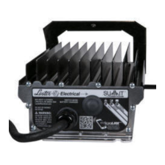
CHARGER RATINGS LABEL The ratings label is located on the back of the charger. The label provides the model (MODEL), part number (PART NO), serial number (SERIAL NO), AC input ratings (INPUT), and DC output ratings (OUTPUT, CELLS, and AH) of the charger. The amp-hour (AH) rating indicates the full range of battery capacities that are recommended for use with this charger. -
Page 3: Table Of Contents
TABLE OF CONTENTS CHARGER RATINGS LABEL ....................2 TABLE OF CONTENTS ......................2 IMPORTANT SAFETY INSTRUCTIONS ................... 4 1. INTRODUCTION ........................6 2. RECEIVING AND INSTALLING THE CHARGER..............6 3. BATTERY TYPE ........................8 4. OFF-BOARD (SHELF) VERSUS ON-BOARD (BUILT-IN) CHARGERS ......9 4.1 Off-Board Chargers .................... -
Page 4: Important Safety Instructions
IMPORTANT SAFETY INSTRUCTIONS SAVE THESE INSTRUCTIONS – This manual contains important safety and operating instructions. Before using battery charger, read all instructions and cautionary markings on battery charger, battery, and product using battery. LOOK FOR THIS SYMBOL TO POINT OUT SAFETY PRECAUTIONS. IT MEANS: BE ALERT—YOUR SAFETY IS INVOLVED. - Page 5 WHEN THE CHARGER IS OPERATING. KEEP SPARKS, FLAME, AND SMOKING MATERIALS AWAY FROM BATTERIES. WARNING: ALWAYS SHIELD EYES WHEN WORKING NEAR BATTERIES. DO NOT PUT WRENCHES OR OTHER METAL OBJECTS ACROSS BATTERY TERMINAL OR BATTERY TOP. ARCING OR EXPLOSION OF THE BATTERY CAN RESULT. WARNING: BATTERIES PRODUCE HYDROGEN GAS, WHICH CAN EXPLODE IF IGNITED.
-
Page 6: Introduction
1. INTRODUCTION This switch mode (high frequency) industrial battery charger features advanced charge and termination algorithms designed to optimize both daily battery capacity and overall battery life. The charger is convection cooled with no moving parts, sealed, and designed to provide maximum reliability. The universal AC input enables the charger to be used with a wide range of AC voltages and frequencies, and the charger includes high efficiency and power factor. - Page 7 Figure 2-1: Charger Mounting Recommendations Figure 2-2: Charger Dimensions and Mounting Slot Locations (Case #1) User’s Manual Summit Series ® 7 of 20...
-
Page 8: Battery Type
Figure 2-3: Charger Dimensions and Mounting Slot Locations (Case #2) 3. BATTERY TYPE This charger was factory-configured to charge the type of battery indicated in the BATTERY field on the charger ratings label (for example, “Wet”). The 13 and 14 characters in the charger part number, available in the PART NO field on the charger ratings label, provide the battery profile code for the primary battery profile. -
Page 9: Off-Board (Shelf) Versus On-Board (Built-In) Chargers
120 volts (or 240 volts as appropriate). If the input plug does not fit the power outlet, contact Lester Electrical for the proper cord set terminating in an attachment plug of the proper configuration for the power outlet. -
Page 10: Dc Output
CAUTION: TO REDUCE THE RISK OF ELECTRIC SHOCK OR FIRE, DISCONNECT AC POWER FROM THE CHARGER BEFORE INSTALLING OR REMOVING UNIT. DANGER: NEVER ALTER THE AC POWER CORD OR PLUG PROVIDED. IF IT WILL NOT FIT AN OUTLET, OBTAIN THE CORRECT CHARGER IEC AC CORDSET FOR THE OUTLET, OR HAVE A PROPER OUTLET INSTALLED BY A QUALIFIED ELECTRICIAN. -
Page 11: Battery Temperature Sensor (Optional)
The lockout control wire is intended to be connected to the motor speed controller (MSC) lockout/interlock input. An internal pull-up resistor to battery positive (+) is included in order to pull the MSC lockout input high when the charger lockout control signal is not active. Option #2 An external DC relay coil, with a minimum 2 kΩ... -
Page 12: Personal Safety Precautions
7. Cold batteries require more time to fully charge. When the temperature falls below 65°F, the batteries should be placed on charge as soon after use as possible. 8. The tops of batteries and battery hold downs must be kept clean and dry at all times to prevent excessive self discharge and the flow of current between the battery posts and frame. -
Page 13: Off-Board Charger Operation
WARNING: ALWAYS SHIELD EYES WHEN WORKING NEAR BATTERIES. DO NOT PUT WRENCHES OR OTHER METAL OBJECTS ACROSS BATTERY TERMINALS OR THE BATTERY TOP. ARCING OR EXPLOSION OF THE BATTERY CAN RESULT! WARNING: DO NOT DISCONNECT THE CHARGER DC OUTPUT CONNECTOR FROM THE BATTERY CONNECTOR WHILE A CHARGE CYCLE IS IN PROGRESS. -
Page 14: On-Board Charger Operation
10.2 On-Board Charger Operation If the charger was factory-configured for on-board use, follow these operating instructions: 1. Ensure that the vehicle/equipment that the charger is mounted on is turned off. 2. With the charger AC power cord disconnected from the AC outlet, connect the charger DC output connector/plug to the battery connector/receptacle (most likely already connected or hard wired). -
Page 15: Led Indicators
11. LED INDICATORS The charger includes three (3) LEDs to indicate charger status and fault information. The functionality of the LEDs is outlined below. If the charger is equipped with a remote LED assembly, this assembly also includes three (3) LEDs with identical functionality. CHARGE STATUS (yellow) Indicates charge cycle status. -
Page 16: Faults
(< 10V). NO AC – AC power was lost during Slow Blink charging. Charge cycle will restart when AC power returns. HARDWARE FAULT – Contact Lester Slow Blink Slow Blink Electrical. HARDWARE FAULT – Contact Lester Slow Blink Slow Blink Electrical. -
Page 17: Troubleshooting
13. TROUBLESHOOTING The charger was fully tested and calibrated before leaving the factory. It was delivered ready to charge. If properly installed, the charger should require very little attention. If improper charger operation occurs, it will require repair by a qualified service technician. CAUTION: DO NOT OPERATE THE CHARGER IF IT IS DAMAGED OR APPEARS TO BE MALFUNCTIONING. -
Page 18: Specifications
14. SPECIFICATIONS AC Input Voltage range, rated 100-230 Vac Voltage range, operating 90-264 Vac (< 100 Vac: reduced power) Frequency, rated 50-60 Hz Frequency, operating 45-65 Hz Phase Single-phase Current, maximum 27790, 27800, 28110, 28120, 27940, 27950: 8A 28000, 28230: 12A Protection Current limit, surge, transient, under voltage DC Output... - Page 19 NOTES User’s Manual Summit Series ® 19 of 20...
- Page 20 Represented By: 39251H User’s Manual Summit Series ® 20 of 20...
Need help?
Do you have a question about the SUMMIT 27790 and is the answer not in the manual?
Questions and answers