Sharp MD-MX30 Service Manual
Md compact component system
Hide thumbs
Also See for MD-MX30:
- Operation manual (44 pages) ,
- Operation manual (44 pages) ,
- Quick manual (4 pages)
Table of Contents
Advertisement
(MD-MX30W only)
SAFETY PRECAUTION FOR SERVICE MANUAL (FOR MD-MX30W) ............................................................................ 2
IMPORTANT SERVICE NOTES (FOR U.S.A. ONLY) ....................................................................................................... 3
VOLTAGE SELECTION (FOR MD-MX30W) ..................................................................................................................... 3
SPECIFICATIONS (FOR MD-MX30) ................................................................................................................................. 4
SPECIFICATIONS (FOR MD-MX30W) .............................................................................................................................. 5
NAMES OF PARTS ........................................................................................................................................................... 6
OPERATION MANUAL ...................................................................................................................................................... 8
DISASSEMBLY ................................................................................................................................................................ 10
REMOVING AND REINSTALLING THE MAIN PARTS ................................................................................................... 12
TEST MODE .................................................................................................................................................................... 15
ADJUSTMENT ................................................................................................................................................................. 20
EEPROM WRITING PROCEDURE ................................................................................................................................. 28
EXPLANATION OF ERROR DISPLAY ............................................................................................................................ 30
NOTES ON SCHEMATIC DIAGRAM .............................................................................................................................. 31
TYPE OF TRANSISTOR AND LED ................................................................................................................................. 31
BLOCK DIAGRAM ........................................................................................................................................................... 32
SCHEMATIC DIAGRAM / WIRING SIDE OF P.W.BOARD ............................................................................................. 37
WAVEFORMS OF CD CIRCUIT ...................................................................................................................................... 65
WAVEFORMS OF MD CIRCUIT ..................................................................................................................................... 66
TROUBLESHOOTING (CD SECTION) ........................................................................................................................... 68
TROUBLESHOOTING (MD SECTION) ........................................................................................................................... 72
FUNCTION TABLE OF IC ................................................................................................................................................ 76
REPLACEMENT PARTS LIST/EXPLODED VIEW/PACKING OF THE SET (FOR U.S.A.)
SERVICE MANUAL
CONTENTS
SHARP CORPORATION
- 1 -
MD-MX30
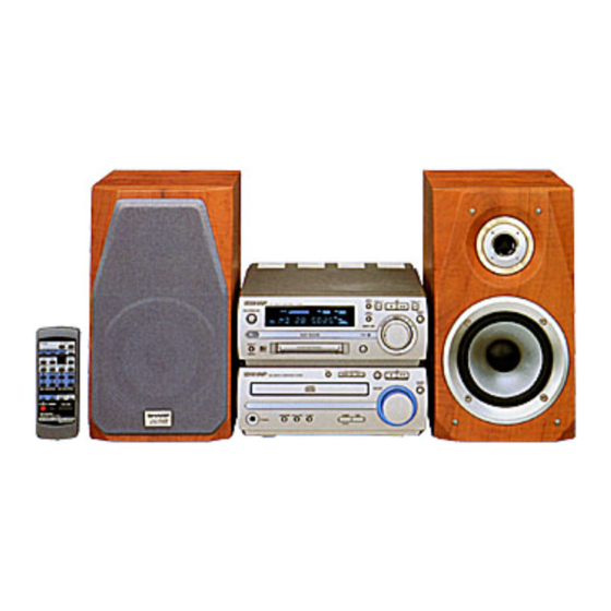
MD-MX30 MD Compact Component System
consisting of MD-MX30(main unit) and CP-
MX30(speaker system).
MD-MX30W
MD-MX30W MD Compact Component System
consisting of MD-MX30W(main unit) and CP-
MX30W(speaker system).
• In the interests of user-safety the set should be restored to its original
condition and only parts identical to those specified should be used.
This document has been published to be used
for after sales service only.
The contents are subject to change without notice.
MD-MX30/MX30W
No.S4025MDMX30//
Page
Advertisement
Table of Contents
Troubleshooting

Related Manuals for Sharp MD-MX30


Summary of Contents for Sharp MD-MX30
-
Page 1: Table Of Contents
MD-MX30/MX30W SERVICE MANUAL No.S4025MDMX30// MD-MX30 MD-MX30 MD Compact Component System consisting of MD-MX30(main unit) and CP- MX30(speaker system). MD-MX30W MD-MX30W MD Compact Component System consisting of MD-MX30W(main unit) and CP- MX30W(speaker system). (MD-MX30W only) • In the interests of user-safety the set should be restored to its original condition and only parts identical to those specified should be used. -
Page 2: Safety Precaution For Service Manual(For Md-Mx30W)
MD-MX30/MX30W SAFETY PRECAUTION FOR SERVICE MANUAL(For MD-MX30W) WARNINGS (CD) WARNINGS (MD) THE AEL (ACCESSIBLE EMISSION LEVEL) OF THE LASER POWER The AEL (ACCESSIBLE EMISSION LEVEL) of the laser power OUTPUT IS LESS THAN CLASS 1 BUT THE LASER COMPONENT output is less than class 1 but the laser component is capable IS CAPABLE OF EMITTING RADIATION EXCEEDING THE LIMIT of emitting radiation exceeding the limit for class 1. -
Page 3: Important Service Notes (For U.s.a.only)
MD-MX30/MX30W FOR A COMPLETE DESCRIPTION OF THE OPERATION OF THIS UNIT, PLEASE REFER TO THE OPERATION MANUAL. IMPORTANT SERVICE NOTES (For U.S.A.Only) BEFORE RETURNING THE AUDIO PRODUCT (Fire & Shock Hazard) Before returning the audio product to the user, perform the following safety checks. -
Page 4: Specifications (For Md-Mx30)
MD-MX30/MX30W SPECIFICATIONS (For MD-MX30) General Compact disc player section Power source: AC 120 V, 60 Hz Type: Drawer type compact disc player Power Signal readout: Non-contact, 3-beam semiconductor consumption: laser pickup Dimensions: Width; 8-1/2" (215 mm) Rotation speed: 200 - 500 rpm CLV, Approx. -
Page 5: Specifications (For Md-Mx30W)
MD-MX30/MX30W SPECIFICATIONS (For MD-MX30W) General Compact disc player section Power source: AC 110/127/220/230-240 V, 50/60 Hz Type: Drawer type compact disc player Power Signal readout: Non-contact, 3-beam semiconductor laser pickup consumption: 70 W Rotation speed: 200 - 500 rpm CLV, Approx. -
Page 6: Names Of Parts
24. Extra Bass Button 25. Tuner (Band) Button 26. Auxiliary Button 27. Volume Control 28. Volume Select Button Rear panel(For MD-MX30) MD-MX30 1. FM 75 Ohms Antenna Terminal 2. Antenna Ground Terminal 3. AM Loop Antenna Terminal 4. Auxiliary Input Jacks 5. - Page 7 MD-MX30/MX30W Display window 1. FM Stereo Indicator 2. FM Stereo Mode Indicator 2 3 4 5 6 3. Track Edit Indicator 4. Play/Pause Indicator 5. Repeat Indicator 6. TOC Indicator 7. Level Meters 8. Digital Recording Indicator 9. CD Indicator 10.
-
Page 8: Operation Manual
MD-MX30/MX30W OPERATION MANUAL – 8 –... - Page 9 MD-MX30/MX30W – 9 –...
-
Page 10: Disassembly
MD-MX30/MX30W DISASSEMBLY Notes for servicing (For MD-MX30 only) Caution on Disassembly • This model is equipped with a fan. If you remove the fan to The disassembling the machine or assembling it after service the unit, it enters the protection mode and the... - Page 11 (D3) x1 MAIN PWB (D1) x1 ø3 x10mm VOLUME PWB HOLDER PWB (D2) x2 (D1) x1 ø3 x10mm (D2) x1 Lug(MD-MX30 Only) (D3) x1 (D3) x1 (E1) x2 (J3) x1 ø3 x10mm TUNER PWB (E1) x2 Washer ø3 x10mm Volume Holder...
-
Page 12: Removing And Reinstalling The Main Parts
MD-MX30/MX30W (P1)x1 SPEAKER ø2x 3mm Shield Case,Top STEP REMOVAL PROCEDURE FIGURE (P1)x1 Net Frame 1. Net ..... (A1) x1 12-2 ø2x 3mm Woofer 2. Screw ....(A2) x4 12-3 Tweeter 3. Screw ....(A3) x6 (P1)x1 MD MECHANISM ø2x 3mm... - Page 13 MD-MX30/MX30W How to remove the MD loading PWB/loadeing (B1)x1 motor ø1.7x 6mm (See Fig. 13-1) 1. Remove the screw (B1) x 1 pc. Loading Motor 2. Remove the Hoock (B2) x 3 pcs., and remove the MD Loading PWB. 3. Remove the screw (B3) x 2 pcs., and remove the Loading Loading Motor PWB motor.
-
Page 14: Cd Mechanism Section
MD-MX30/MX30W CD MECHANISM SECTION ( A1 ) x2 ø2.6 x 6 mm For details about the procedure to remove the CD mechanism from the main unit, refer to Disassembly Procedure, Steps 1- Optical Pickup 4 ,7 and 11-13 in the main unit and also the CD section. -
Page 15: Test Mode
MD-MX30/MX30W TEST MODE Press specified buttons simultaneously to enter the following test modes. System section TEST 1: Factory setting (version number and destination) TEST 2: Soft reset MD section TEST 3: MD test 1 (adjustment, test, etc.) CD section TEST 4: CD test... - Page 16 MD-MX30/MX30W TEST 2 Soft reset Object: Reinitializing the unit. Function: Reinitializing all functions. Operation: "ALL CLEAR" appears and the unit reinitializes all functions and then turns power on. Leaving the test mode After reinitializing by soft reset, the unit enters the normal power-on state.
- Page 17 MD-MX30/MX30W Button to press Press Function Main unit Remote control [ON/STAND-BY] Once Power on and off. Turns the power off when POWER ON and on when POWER OFF. [EQUALIZER] Once Sending test mode menus. To servo adjustment mode. (Menus concerning adjustment and EEPROM.)
- Page 18 MD-MX30/MX30W When an MD is not loaded: "_EJECT_" appears. Indication appears as shown in Figure 18-1 when a disc is not loaded. When a disc is loaded, the MD microcomputer enters the AUTO YOBI mode. The received character data will be displayed as Figure 17-1 (page 17).
- Page 19 MD-MX30/MX30W Tuner section Pressing the specified buttons performs the following 3 test operations. The operations are performed when POWER ON. When they are completed, the unit enters the normal power-on operation state. TEST 5 Tuner test frequency preset Object: Presetting the test frequency for factory test.
-
Page 20: Adjustment
MD-MX30/MX30W ADJUSTMENT TUNER SECTION fL: Low-range frequency • Setting the Test Mode fH: High-range frequency While holding down the TUNER(BAND) button and the MD fC: Center-range frequency PLAY button, press the ON/STAND-BY button. Frequencies • AM adjustment and confirmation are rewritten in memory as shown in table 18. Call them using AM signal oscillator Frequency 400 Hz, 30%, AM modulation the JOG DIAL for tuner circuit adjustment and check. - Page 21 MD-MX30/MX30W MD SECTION Enter the test mode, adjust or set as shown in the following table according to the repair operations. Execution item Checking Writing the Writing the TEMP AUTO-YOBI AUTO- AUTO-FAB Operation check EEPROM EEPROM EEPROM required adjustment adjustment...
- Page 22 MD-MX30/MX30W Test Mode Test mode setting method 1. While holding down the MD PLAY and SURROUND buttons simultaneously, press the ON/STAND-BY button. (State A is changed to state B .) 2. Insert the playback-only disc 1 (high reflection disc) or the recordable disc 2 (low reflection disc). (State is changed to C.) If "R/ P WHICH?"...
- Page 23 MD-MX30/MX30W 1. EJECT mode Setting Method Step No. Remarks Display Step 1 Test mode EJECT state [ _ _ E J E C T _ _ _ ] Step 2 Press the DISPLAY button. Playback power output state [ p p w _ _ _ _ _ _ _ ] Step 3 Press the DISPLAY button.
- Page 24 MD-MX30/MX30W 4. AUTO FAB adjustment mode Setting Method Step No. Remarks Display Step 1 Test mode STOP state The AUTO preliminary adjustment should have been completed. [ t s m 1 A Step 2 Press the EQUALIZER button three times. AUTO adjustment menu...
- Page 25 MD-MX30/MX30W C) Tracking setting Step No. Setting Method Display Step 10 Press he EQUALIZER button. [[T R B L V t _ _ Step 11 Press the EQUALIZER button. [T R K L V o _ _ Step 12 Press the EQUALIZER button.
- Page 26 MD-MX30/MX30W Setting Method Step No. Display Step 17 Press the EQUALIZER button. [G A L S G _ _ _ Step 18 Press the EQUALIZER button. [H A L S O F S _ Step 19 Press the EQUALIZER button.
- Page 27 MD-MX30/MX30W Lead-in switch position measurement mode Insert the high reflection test disk TGYS1. Note: Adjust the lead-in switch position within the range of FF85 - FFD2. 1. Measure the lead-in switch position. Loosen the screw (A1) x 1 pc. which fixes the mechanism switch PWB.
-
Page 28: Eeprom Writing Procedure
MD-MX30/MX30W EEPROM WRITING PROCEDURE EEPROM DATA LIST (Version : 01) EEPROM (IC1402) writing procedure Focus setting 1. Method for setting the reference temperature value Item indication Setting (This setting should be performed quickly at a room temperature, between 21 C and 29 C when the PWB is not hot.) - Page 29 MD-MX30/MX30W Sled setting Control setting Item indication Setting Item indication Setting S L G C O N T R L 1 S L 2 C O N T R L 2 S L D L I M S P K L E V m...
-
Page 30: Explanation Of Error Display
MD-MX30/MX30W EXPLANATION OF ERROR DISPLAY MD error messages Error message Description Remarks 'BLANK MD' No track is recorded on the disc 'Can't COPY' Digital recording from a copy prohibited source 'Can't EDIT' Editing impossible 'Can't REC' Sound memory overflow while recording... -
Page 31: Notes On Schematic Diagram
MD-MX30/MX30W NOTES ON SCHEMATIC DIAGRAM Resistor: The indicated voltage in each section is the one measured by Digital To differentiate the units of resistors, such symbol as K and M are Multimeter between such a section and the chassis with no signal used: the symbol K means 1000 ohm and the symbol M means 1000 given. -
Page 32: Block Diagram
MD-MX30/MX30W TUNER T302 SO301B ANTENNA COIL TERMINAL +12V(A) VOLTAGE REGULATOR MDAVCC T306 TO MD MDDVDD FM 75 COIL CD+7V TO CD FE301 IF OUT FM FRONT END SWITCHING M-COM.CONT. +B12 +12V LINE PULL-UP Q360 +5V(SWD) FM/AM VOLTAGE TO FAN MOTOR... - Page 33 MD-MX30/MX30W MD-MX30W MD-MX30 VOLTAGE MAIN REGULATOR -12V(A) POWER POWER IC802 F801,F802 KIA7812AP MD-MX30: 4A 125V T991 T991 VOLTAGE MD-MX30W: T4A L 250V POWER TRANSFORMER (MAIN) REGULATOR POWER TRANSFORMER (MAIN) F801 D801 F802 D802-D805 VOLTAGE F803 F803 REGULATOR 2.5A 125V T2.5A L 250V...
- Page 34 MD-MX30/MX30W CNPD TO MAIN TO MAIN SECTION CNP8 TO CNS8 CD SERVO LRSY DATACK CDGND1 DATA CNP7 VOLTAGE REGULATOR +B11 CD+7V +B11 +B10 +3.3V +B10 PICKUP UNIT 14 15 18 36 49 50 44 80 79 78 77 72 FIN1...
- Page 35 1 2 3 4 5 6 7 8 9 10 11 12 13 14 15 16 17 18 19 20 21 22 23 24 25 26 27 28 29 30 –30V –B1 RMD01 REMOTE REMOCON SENSOR MD-MX30 Only VOLUME JOG SWITCH SWD02 MULTI JOG SWITCH +5V(D) SWD01...
- Page 36 MD-MX30/MX30W 9 10 11 12 13 14 15 16 17 18 19 20 21 22 23 24 25 26 27 28 MECHANISM +4.75~5.25V 70 34 25 12 20 33 21 32 31 IC1401 IX0326AW MD SYSTEM MICROCOMPUTER IC1402 58X2402T EEPROM...
-
Page 37: Schematic Diagram / Wiring Side Of P.w.board
MD-MX30/MX30W TP1124 MD MAIN PWB-E TP1125 C1108 C1110 TP1131 0.47 C1111 0.0047 0.47 POUT ADAGC 0.7V ADIPI 1.6V TP1132 0.7V 1.6V TP1133 EFMO-I & DIFF 0.7V AOUT-IN EOUT-IN TP1134 1.6V 0.7V DIFF ADLPFO C1101 IC1101 BOUT-IN ADIP REFI 1.6V 1.6V... - Page 38 MD-MX30/MX30W C1204 0.047 TP1202 TP1213 100 99 98 97 96 95 94 93 92 91 90 89 88 87 86 85 84 83 82 81 80 79 78 77 76 TP1212 TP1201 1.48V 1.55V DADATA C1201 3.2V DADATA AVCC EFMO-I ADDATA 1.6V...
- Page 39 MD-MX30/MX30W MD SIGNAL DADATA RECORD SIGNAL ADDATA DFCK BCLK LRCK C1206 0.0012 R1212 C1210 22P (CH) R1215 XL1201 3.8688MHz TP1214 10 9 8 5 4 3 2 1 L1551 IC1202 0.47 H TP1530 IX2474AF TO CD SERVO CDLRCK TP1531 4MBIT D-RAM...
- Page 40 TUNNING TIMER/ CD_SQOUT MD STOP MD PLAY EDIT DOWN MEMORY/ENTER DELETE SWD09 SWD08 SWD07 SWD06 SWD05 SWD04 SWD03 BiDA1 MD-MX30:From Serial Number [No.004xxxxx] CDA1 33/16 RDA2 MD-MX30W QDA2 KRC107M RD63 RD62 RD65 RD64 RD61 RD60 RD59 RDA1 2.7K 8.2K 5.6K 3.3K...
- Page 41 17 18 19 20 21 22 23 24 25 26 27 28 29 30 DOWN REMO RD84 CD20 VOL_JOG 0.001 CD19 0.001 CNPD03 FWD03 CNPD04 VOLUME PWB-C RD27 RD49 MD-MX30 Only RMD01 REMOTE MULTI SENSOR TO CHASSIS JOG SW 4.9V SWD01 MAIN SECTION RD21 P45 12 - B 4.9V DOWN CNPV02...
- Page 42 MD-MX30/MX30W MAIN PWB-A1(1/2) RU31 FM SIGNAL MD SIGNAL RU32 CD SIGNAL CU17 0.33/50 RECORD SIGNAL CU15 RU11 0.22/50 RU09 MD-MX30W Only 4.2V 2.7K 4.2V SWU01 CU09 CU11 CU13 SPAN SELECTOR 2.2/50 0.001(ML) 1/50 RU07 50/9 4.2V CU07 4.2V 2.2/50 4.2V...
- Page 43 MD-MX30/MX30W AUX INPUT JTU01 RU19 L CH CU21 RU17 CU22 RU18 R CH ICU01 CU32 RU20 100/16 LC75341 AUDIO RU30 CU31 PROCESSOR 0.022 RU33 CU41 0.001 (1/2) RU34 8.4V (1/2) (OS-CON) CU45 DU06 3.3/16 DS1SS133 (OS-CON) CU30 VREF 22/16 4.2V...
- Page 44 MD-MX30/MX30W MAIN PWB-A1(2/2) ICV01 STK40203 POWER AMP. +OUT +OUT -VCC -OUT -OUT 4.8V QV02 KTC3199GR CV11 CV12 0.022 0.022 RV16 RV15 6.8K 6.8K RV11 RV13 RV12 RV14 0.2(1) -23.6V 3.3K 0.2(1) 3.3K CV09 CV10 RV07 RV08 CV05 3.3P 3.3P 220P...
- Page 45 RV55 KTC3199 GR 47/25 4.7K 470K MD-MX30 ONLY CNS901 To Serial Number [No.003xxxxx] CNP901 POWER TO POWER SECTION P49 4 - A : MD-MX30 P49 4 - E : MD-MX30W BIV01 CV61 0.001 CHASSIS LUGV01 D811 R809 DV06 1N4004S DV05...
- Page 46 MD-MX30/MX30W CD SERVO PWB-A2 CD SIGNAL TIN1 FIN1 0.047 (ML) FIN2 TIN2 3.9M 100/10 2.2/50 FIN1 CNS1 1.7V 3.3V 0.022 0.022 ODRV FIN2 RFSW 100P 1.7V 1.7V 5.6P 120K AGCON 1.2K TIN1 6.8K 1.7V 1.7V 1.0V 47/6.3 4.7K TIN2 1.7V 1.7V...
- Page 47 3.3/16 CNP8 AGON (OS-CON) 2.2 H AGND 0.82 H 4.7K LD_M+ LD_M- DGND (1/4) CD+7V 4.7K CDGND1 MD-MX30 Only After a serial number 47/10 FWU05 0.001 [No.004xxxxx],eliminated. DS1SS133 CDGND2 CNP6 DS1SS133 BI 4 CNS4 CD LOADING LOADING M+ 2.2/50 MOTOR 0.56...
- Page 48 MD-MX30/MX30W TUNER PWB-A3 TUN/R R370 A_GND TUN/L A+12V D_GND C395 ZD351 0.022 DZ5.1B R391 R389 IC303 3.9K R392 LA1832S R364 FM IF DET/FM MPX/AM IF R363 R354 R362 R361 3.9K C370 R359 1/50 1.8K 3.9V(1.3V) C372 PHASE MO/ST C373 (FM/AM) 1/50 1.3V...
- Page 49 MD-MX30/MX30W MD-MX30 CNP901 POWER TRANSFORMER(SUB) T901 D900-D903 1N4004S D902 D900 D903 C903 POWER PWB-B3 470/25 R903 0.8V R900 D906 4.7M R902 DS1SS133 Q900 4.7K KTC3199 GR RL900 RELAY C900 0.0047/250V T.F. 150 C CNP900 BI900 L900 POWER PWB-B2 SO900 AC INPUT SOCKET...
- Page 50 MD-MX30/MX30W CNS901 TO POWER PWB CNP901 P58 5 - D P58 5 - C TO POWER PWB CHASSIS CHASSIS CNS802 DU05 BiU02 9 8 7 6 5 4 3 2 1 CNP802 D813 C804 D803 C825 C811 C824 R802 D805...
- Page 51 RU32 1 2 3 4 RS02 CU07 RU07 ICS01 CU11 8 7 6 5 RS13 CS01 CS02 RS11 RS05 QV53 CS09 MAIN PWB-A1 MD-MX30 ONLY To Serial Number [No.003xxxxx] CHASSIS Figure 51 WIRING SIDE OF P.W.BOARD (2/15) – 51 –...
- Page 52 MD-MX30/MX30W CNS901 TO POWER PWB CNP901 MD-MX30:P58 11 - D MD-MX30W:P59 11 - D F801,802 MD-MX30:4A 125V MD-MX30W:T4A L 250V MD-MX30:P58 11 - C MD-MX30W:P59 11 - C MD-MX30 ONLY TO POWER PWB CHASSIS CHASSIS CNS802 DU05 BiU02 F802 F801...
- Page 53 RS06 RU32 1 2 3 4 RS02 CU07 RU07 ICS01 CU11 8 7 6 5 RS13 CS01 CS02 RS11 RS05 QV53 CS09 MAIN PWB-A1 MD-MX30:From Serial Number [No.004xxxxx] MD-MX30W CHASSIS Figure 53 WIRING SIDE OF P.W.BOARD (4/15) – 53 –...
- Page 54 MD-MX30/MX30W P51 12 - B TO MAIN PWB CNPU02 SWD07 RD53 RD54 TUNNING SWD08 DOWN SWD05 SWD06 TIMER/ SWD04 RD32 DELETE TUNNING CD03 FWD01 MD STOP RD34 MD PLAY RD89 SWD09 NAME/ CNSD01 RD35 RD36 TOC EDIT RD37 MEMORY/ RD39...
- Page 55 MD-MX30/MX30W MD-MX30 ONLY: DISPLAY PWB-B1 To Serial Number [No.003xxxxx] 22 23 24 25 26 27 28 29 30 31 32 33 34 35 36 37 38 39 40 41 42 43 44 45 46 47 48 49 50 51 52 53 54 55 56...
- Page 56 MD-MX30/MX30W P53 12 - B TO MAIN PWB CNPU02 SWD07 RD53 RD54 TUNNING SWD08 DOWN TIMER/ SWD05 SWD06 SWD04 RD32 DELETE TUNNING CD03 MD STOP FWD01 MD PLAY RD34 RD89 SWD09 NAME/ CNSD01 RD35 RD36 TOC EDIT RD37 MEMORY/ RD39...
- Page 57 MD-MX30/MX30W MD-MX30:From Serial Number [No.004xxxxx] DISPLAY PWB-B1 MD-MX30W 22 23 24 25 26 27 28 29 30 31 32 33 34 35 36 37 38 39 40 41 42 43 44 45 46 47 48 49 50 51 52 53 54 55 56...
- Page 58 MD-MX30/MX30W MD-MX30 F0575AW-1/2 CNS900 POWER PWB-B3 T.F. F803 2.5A 125V BI900 2.5A 250V BI902 CNS802 CNP802 P50 or P52 3 - B T991 POWER TRANSFORMER TO MAIN PWB (MAIN) POWER PWB-B2 D903 C902 C903 D902 CNP901 D901 D900 Q900 CNS901...
- Page 59 MD-MX30/MX30W MD-MX30W F0574AW-2/3 CNS900 POWER PWB-B3 T.F. BI900 F803 T2.5A L 250V BI902 CNS802 CNP802 P52 3 - B T991 POWER TRANSFORMER TO MAIN PWB (MAIN) POWER PWB-B2 D903 C902 C903 D902 CNP901 D901 D900 Q900 CNS901 C901 P52 5 - A...
- Page 60 CNS10 TO MD CHASSIS CD SERVO PWB-A2 LOADING MOTOR MD-MX30: F0573AW-2 MD-MX30W: F0572AW-2 MD-MX30 Only After a serial namber [No.004xxxxx],eliminated. CNS4 CNP6 BI 4 ZD60 1 2 3 • The numbers are waveform numbers shown in page 65. Figure 60 WIRING SIDE OF P.W.BOARD (11/15)
- Page 61 MD-MX30/MX30W P63 8 - F TO MD MD MAIN PWB CN1101 MAGNETIC HEAD(34) RECORD FLEXIBLE TO MD MAIN CN1300 P63 8 - B CW1903 MD PICKUP UNIT(35) MD MECHANISM MD LOADING SWITCH PWB-F1 PWB-F2 M902 MD SLED MOTOR SW1934 PLAY...
- Page 62 MD-MX30/MX30W : Through-hole where the top and bottom patterns are connected. C1707 IC1702 C1509 C1606 L1552 Q1700 R1704 R1516 L1551 C1304 R1513 R1705 R1511 Q1701 R1703 C1701 C1704 C1710 C1712 L1701 R1712 C1716 R1711 C1803 C1800 R1714 C1700 C1711 C1714...
- Page 63 MD-MX30/MX30W P51 orP53 8,9 - C TO MAIN PWB CNPU04 P61 5 - B TO MAGNET HEAD CW1501 CW1903 TP1543 TP1701 TP1702 TP1520 TP1519 CN1501 TP1301 TP1521 CN1502 TP1530 TP1300 TP1517 R1301 TP1515 TP1512 R1537 R1533 R1535 TP1507 C1300 TP1531...
- Page 64 MD-MX30/MX30W TUNER PWB-A3 CNP302 FWU06 CNPU06 P51 or P53 8 - E TO MAIN PWB R391 MD-MX30: R364 R363 F0573AW-3 R399 R361 R362 MD-MX30W: R392 C371 F0572AW-3 C372 C373 ZD351 C396 C374 C376 R357 C353 R389 X351 C368 C357 R356...
-
Page 65: Waveforms Of Cd Circuit
MD-MX30/MX30W WAVEFORMS OF CD CIRCUIT Stopped 1999/04/05 17:33:17 Stopped CH1=500mV CH3=1V CH4=1V 500ms/div CH1=500mV CH3=500mV 500ms/div DC 10:1 DC 10:1 DC 10:1 (500ms/div) DC 10:1 DC 10:1 (500ms/div) NORM:20kS/s NORM:20kS/s PDO1 IC2 1 IC2 24 PDO2 IC2 2 IC2 23... -
Page 66: Waveforms Of Md Circuit
MD-MX30/MX30W WAVEFORMS OF MD CIRCUIT PLAY STATE PIT PLAY Stopped Stopped NORM: 1M S/s 1997 / 08 / 04 13:35:24 NORM: 100M S/s 1997 / 08 / 04 09:30:15 200mV 1ms/div CH1 500mV 500ns/div DC 10:1 DC 10:1 AC 10:1... - Page 67 MD-MX30/MX30W PLAY Stopped Stopped NORM: 1k S/s NORM: 100M S/s 1997 / 08 / 04 14:19:52 1997 / 08 / 04 10:35:14 1s/div 500ns/div DC 10:1 DC 10:1 DC 10:1 DC 10:1 DC 10:1 DC 10:1 Filter Filter SMOOTH SMOOTH...
-
Page 68: Troubleshooting (Cd Section)
MD-MX30/MX30W TROUBLE SHOOTING CD SECTION When the CD does not function When the CD section does not operate when the objective lens of the optical pickup is dirty, this section may not operate. Clean the objective lens, and check the playback operation. When this section does not operate even after the above step is taken, check the following items. - Page 69 MD-MX30/MX30W (1) Focus-HF system check Stopped CH1=500mV CH3=500mV 500ms/div "NO DISC"appears when you load a disc and close the DC 10:1 DC 10:1 (500ms/div) NORM:20kS/s tray. Playback operation starts even if no disc is loaded. v/DIV 500mV =Filter= =Offset= =Record Length=...
- Page 70 MD-MX30/MX30W (2) Tracking system check Check the TE waveform at pin 18 on IC1. The tracking servo is not activated. If the waveform shown in Figure 70-1 appears and soon after Check the peripheral circuits at pins 18 and 19 on IC1, pin 23 on NO DISC appears.
- Page 71 MD-MX30/MX30W (4) PLL system check Stopped 1999/04/05 17:33:17 CH1=500mV CH3=1V CH4=1V 500ms/div DC 10:1 DC 10:1 DC 10:1 (500ms/div) NORM:20kS/s PDO1 When a disc is loaded, start play operation. The HF waveform is normal, but the TOC data cannot be PDO2 read.
-
Page 72: Troubleshooting (Md Section)
MD-MX30/MX30W MD SECTION When MD fails to operate If the objective lens of optical pickup is contaminated, MD may fail to operate. At first, clean the objective lens to check playback operation. If MD fails persistently to operate, perform checks as follows. - Page 73 MD-MX30/MX30W • Disc loading is not normal. Is disc loaded when it is inserted? Check the power supply PWB, system Is +5V to +6V applied to the pins 17 and 18 of CN1501? PWB, and CN1501. Is pulse input in the pin 6 of CN1501 when reset power supply Check the system PWB and CN1501.
- Page 74 MD-MX30/MX30W • Normal playback When it has been confirmed that EEPROM value is normal in the TEST mode Is initialization performed normally when high reflection disc is Does the playback time display advance? played back? Check IC1201. Does disc rotate normally?
- Page 75 MD-MX30/MX30W • The spindle motor does not rotate. Check the pins 24 and 25 of IC1201, soldering of peripheral circuit, Is waveform output from the pins 24 and 25 of IC1201 in the step and parts. 4 of AUTO auxiliary adjustment mode of TEST mode? Is waveform output from the pins 9 and 10 of IC1601 and the pins Check IC1601, CN1402, and soldering of mechanism switch PWB.
-
Page 76: Function Table Of Ic
MD-MX30/MX30W FUNCTION TABLE OF IC IC1 VHiLA9235M/-1:Servo Amp. (LA9235M) ODRV FIN1 LA9235M RFSW FIN2 AGCON 28 RF- FIN3 FIN4 26 N/C 25 PH 24 BH REF1 ODRV 23 N/C PH/BH 22 RFEV VREF 21 FE- 20 FE LDOF 19 TE-... - Page 77 MD-MX30/MX30W IC2 VHiLC78641E-1:Servo/Signal Control (LC78641E) (2/3) Terminal Name Input/Output Setting in Reset Pin No. Function PDO1 Output – For PULL Phase-comparison output terminal for built-in VOC control. PDO2 Output – Phase-comparison output terminal for built-in VOC control. Rough servo : OFF, phase servo : ON.
- Page 78 MD-MX30/MX30W IC2 VHiLC78641E-1:Servo/Signal Control (LC78641E) (3/3) Pin No. Terminal Name Input/Output Setting in Reset Function LVDD – – L channel Power terminal for L channel. LCHO Output 1/2VDD D/A converter L channel output terminal. LVSS – – Ground terminal for L channel. Surely connected to 0V.
- Page 79 MD-MX30/MX30W IC3 VHiLA6558++-1: Focus/Tracking/Spin/Sled/Roading/Move Driver (LA6558) Function Terminal Name Pin No. VO3- CH3(-)output VO3+ CH3(+)output VO5- CH5(-)output Inversion when input VO5+ CH5(+)output No inversion when input VO4- CH4(-)outputÅ Inversion when input VO4+ CH4(+)output No inversion when input P-GND Power system GND(CH3,4,5)
- Page 80 MD-MX30/MX30W ICD01 RHiX0321AWZZ: System Microcomputer/FL Driver (iX0321AW) (1/2) Input/Output Function Setting in Reset Pin No. Terminal Name Port Name CD-DRF – Output CD Control CD-WRQ – Output CD Control MD-STB – Output MD Control MD LOAD-SW – Input For MD control (DATA when rewriting FLASH) C2-CE –...
- Page 81 MD-MX30/MX30W ICD01 RHiX0321AWZZ: System Microcomputer/FL Driver (iX0321AW) (2/2) Port Name Input/Output Input/Output Function Pin No. Terminal Name – – – seg7 Output seg8 Output seg9 Output seg10 Output seg11 Output seg12 Output seg13 Output seg14 Output seg15 Output seg16 Output...
- Page 82 MD-MX30/MX30W ICV01 VHiSTK40203-1: Power Amp. (STK40203) +VCC Pre. +VCC TR11 TR14 TR15 ch.1 TR12 ch.1 TR10 TR13 TR16 -VCC 14 15 ch.1 ch.1 ch.2 ch.2 ch.2 ch.2 BIAS Pre. -VCC Figure 82-1 BLOCK DIAGRAM OF IC – 82 –...
- Page 83 MD-MX30/MX30W IC1101 VHiiR3R55//-1:RF Signal Processor (iR3R55) Function Terminal Name Pin No. RF signal input terminal 2 . The RF signal received is applied here. RF signal input terminal 1 . The RF signal received is applied here. RF signal input terminal 4 .
- Page 84 MD-MX30/MX30W IC1201 VHiLR376484F1: ENDEC/ATRAC (LR376484F) (1/2) Terminal Name Input/Output Function Pin No. EFMMON Output EFM monitor output AVCC – Analog power EFMI Input EFM signal input from the RF amplifier AGND – Analog ground Input Focus error signal A Input...
- Page 85 MD-MX30/MX30W IC1201 VHiLR376484F1: ENDEC/ATRAC (LR376484F) (2/2) Terminal Name Input/Output Function Pin No. X700KO Output Clock output. f=705.6kHz. When RSTX=0, the clock output is not available. EXPORT0 Output Microcomputer extension output port 0 EXPORT1 Output Microcomputer extension output port 1 TESO1 Output PLLR switching: Microcomputer extension output port 2.
- Page 86 MD-MX30/MX30W IC1401 RH-iX0326AWZZ:MD System Microcomputer (iX0326AW) (1/2) Terminal Name Input/Output Function Pin No. 4M/16M Output 4M/16M DRAM select input OUtput 64M DRAM select input LDVAR Output LDVAR (Laser power output adjustment) ADIS Output ADJS (For automatic adjustment step check) Input...
- Page 87 MD-MX30/MX30W IC1401 RH-iX0326AWZZ:MD System Microcomputer (iX0326AW) (2/2) Terminal Name Input/Output Function Pin No. SYS D2 In/Output SYS D2 (Data bus 2) SYS D1 In/Output SYS D1 (Data bus 1) SYS D0 In/Output SYS D0 (Data bus 0) Output Input/output port P37...
- Page 88 MD-MX30/MX30W IC1101 VHiiR3R55//-1:RF Signal Processor (iR3R55) ADIPI ADIPO DIFF DIFF ADLPFO ADIP 22KO REFI 22KI REFO BIAS RFADD TCGO TCGI AOUT BOUT EOUT LOGIC FOUT Figure 88-1 BLOCK DIAGRAM OF IC IC1202 RH-iX2474AFZZ: 4Mbit D-RAM (iX2474AF) Function Terminal Name Pin No.
- Page 89 MD-MX30/MX30W IC1201 VHiLR376484F1:ENDEC/ATRAC (LR376484F) 75 74 73 72 71 70 69 68 67 66 65 64 63 62 61 60 59 58 57 56 55 54 53 52 51 EFMO TOTMON PLCK TEMON ACRCER SBCK TCRS RAD0 SBSY RAD1 SFSY...
- Page 90 MD-MX30/MX30W IC1701 VHiUDA1347T-1: AD/DA Converter (UDA1347T) Pin No. Terminal Name Function AD converter analog ground SSA(ADC) AD converter analog power DDA(ADC) VINL AD converter input (left) Vref(A) AD converter reference voltage VINR AD converter input (right) AD converter reference voltage N...
-
Page 91: Parts Guide
“HOW TO ORDER REPLACEMENT PARTS” To have your order filled promptly and correctly, please furnish the For U.S.A. only following information. Contact your nearest SHARP Parts Distributor to order. 1. MODEL NUMBER 2. REF. No. 3. PART NO. 4. DESCRIPTION For location of SHARP Parts Distributor, Please call Toll-Free;... - Page 92 VS2SA1162G/-1 AB Silicon,PNP,2SA1162 G T901 RTRNP0266AWZZ J AQ Power (SUB) Q1802 VSUN2214///-1 AB Digital,NPN,UN2214 T991 RTRNP0280AWZZ J BB Power (MAIN) [For MD-MX30] Q1803 VSUN221N///-1 AB Digital,NPN,UN221 N Q1804 VS2SA1242Y/-1 AE Silicon,PNP,2SA1242 Y T991 RTRNP0281AWZZ J Power (MAIN) [For MD-MX30W] Q1805...
- Page 93 [For MD-MX30] C903 VCEAZV1VW477M J AD 470 F,35V,Electrolytic C323 VCTYBT1EF223Z AA 0.022 F,25V [For MD-MX30W] C330 VCCUBT1HJ120J AA 12 pF (UJ),50V [For MD-MX30] C330 VCCUBT1HJ150J AA 15 pF (UJ),50V C1100 RC-KZ0003AWZZ AE 4.7 F,10V [For MD-MX30W] C1101 VCKYTV0JB105K AD 1 F,6.3V...
- Page 94 MD-MX30/MX30W PRICE PRICE PARTS CODE DESCRIPTION PARTS CODE DESCRIPTION RANK RANK C1112 VCCCCY1HH331J J AA 330 pF (CH),50V CD23,24 VCCSMN1HL470J AA 47 pF,50V C1113~1117 VCCCCY1HH271J J AA 270 pF (CH),50V CD25 VCTYMN1EF223Z AA 0.022 F,25V C1118 VCKYTV1CF105Z AB 1 F,16V...
- Page 95 VRD-ST2CD152J AA 1.5 kohms,1/6W R1460,1461 VRS-CY1JB103J AA 10 kohm,1/16W [For MD-MX30W] R1463 VRS-CY1JB103J AA 10 kohm,1/16W R361,362 VRD-ST2CD182J AA 1.8 kohms,1/6W [For MD-MX30] R1510 VRS-CY1JB102J AA 1 kohm,1/16W R363,364 VRD-ST2CD272J AA 2.7 kohms,1/6W R1511 VRS-CY1JB822J AA 8.2 kohms,1/16W [For MD-MX30W]...
- Page 96 AA 1 kohm,1/6W RU58 VRD-MN2BD103J AA 10 kohm,1/8W RD46 VRD-MN2BD102J AA 1 kohm,1/8W RU59 VRD-ST2CD102J AA 1 kohm,1/6W RD47 VRD-ST2CD222J AA 2.2 kohms,1/6W [MD-MX30] RU60 VRD-ST2CD103J AA 10 kohm,1/6W RD48 VRD-ST2CD103J AA 10 kohm,1/6W RU61 VRD-ST2CD183J AA 18 kohms,1/6W RD49 VRD-MN2BD180J...
- Page 97 AD Socket AC Input BI902/CNS802 QCNWN1530AWZZ J AG Connector Ass’y,10-10Pin [For MD-MX30W] BID02/CNSV02 QCNWN1588AWZZ J AH Connector Ass’y,5-5Pin SO900 QSOCA0214AWZZ J AD Socket AC Input [For MD-MX30] BID03 QCNWN1628AWZZ J AC Lead Wire Ass’y,with Lug SOV01 QTANA0415AWZZ J AD Terminal,Speaker BIDA1 QCNWN1687AWZZ J Connector Ass’y,2Pin [For MD-...
- Page 98 LX-HZ0082AFZZ AA Screw,ø4 8mm LX-JZ0010AFFD AA Screw,ø3 10mm GCAB-1183AWSA AR Cabinet,Top LX-JZ0022AFFD AA Screw,ø3 10mm GCABB1199AWSA J AK Cabinet,Rear [For MD-MX30] XBPSD30P06KSO J AB Screw,ø3 6mm GCABB1200AWSA J Cabinet,Rear [For MD-MX30W] XEBSD26P08000 AA Screw,ø2.6 8mm GCOVA1201AWSA J AH Tray,CD XEBSD26P10000 AA Screw,ø2.6 10mm...
- Page 99 AB Label,Energy Star PWB-E 92LPWB3168MDSS J — MD Main [For MD-MX30] PWB-F1,2 QPWBF0554AWZZ J AD MD Mechanism Switch/MD TLABZ0684AWZZ AD Label,Pop [For MD-MX30] Loading Motor (PWB Only) TLABZ0719AWZZ Label,Carton [For Taiwan] TLABZ0721AWZZ Label,Pop [For MD-MX30W] TSPC-0665AWZZ Label,Specification [For CP-MX30] TSPC-0667AWZZ...
- Page 100 MD-MX30/MX30W 306-2 306-1 306-3 305x2 PWB-D Figure 9 CD MECHANISM EXPLODED VIEW – 9 –...
- Page 101 MD-MX30/MX30W MD Mechanism 33x2 512x2 33x2 510x2 M903 SW1934 PWB-E SW1932 SW1933 PWB-F2 SW1931 SW1930 506x2 M902 SW1936 PWB-F1 501x2 M901 505x3 Figure 10 MD MECHANISM EXPLODED VIEW – 10 –...
- Page 102 612x3 MD UNIT 208-1 609x2 241x2 BiV01 607x2 247x4 612x2 614x2 614x2 609x2 612x4 610x2 PWB-A4 Silicon Grease BiU02 (MD-MX30 Only) 610x3 Silicon Grease 604x4 607x2 (MD-MX30W Only) 605x2 601x2 PWB-A2 (MD-MX30W Only) 612x4 PWB-B3 247x2 (MD-MX30W Only) PWB-B2 247x2...
- Page 103 MD-MX30/MX30W Tweeter SP3 (L-CH) SP4 (R-CH) Capacitor 1.5 F/100V (N.P) Woofer SP1 (L-CH) SP2 (R-CH) SP3,4 908x2 TERMINAL 909 910 907x4 904-1 904-3 904-2 ø4 x20mm 907x4 SP1,2 Tweeter SP3 (L-CH) Capacitor SP4 (R-CH) 1.5 F/100V (N.P) Woofer SP1 (L-CH)
- Page 104 SPAKC0940AWZZ TLABR1121AWZZ Packing Case Label,Bar Cord Not Replacement Item © COPYRIGHT 2000 BY SHARP COPORATION SHARP CORPORATION ALL RIGHTS RESERVED. Communication Systems Group Quality & Reliability Control Center No part of this publication may be reproduced, Higashihiroshima, Hiroshima 739-0192, Japan...
Need help?
Do you have a question about the MD-MX30 and is the answer not in the manual?
Questions and answers