Table of Contents
Advertisement
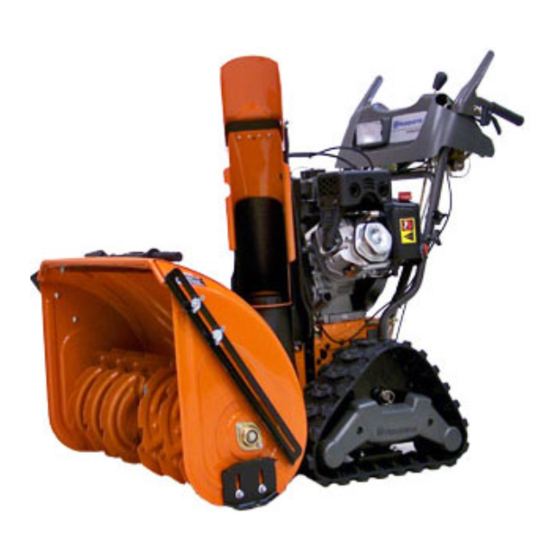
Operator's Manual
1830EXLT
Gasoline containing up to 10% ethanol (E10) is acceptable for use in this machine.
The use of any gasoline exceeding 10% ethanol (E10) will void the product warranty.
Please read the owner's manual carefully and make sure you
532 44 35-68 Rev. 4
English
understand the instructions before using the machine.
Advertisement
Table of Contents

Subscribe to Our Youtube Channel
Related Manuals for Husqvarna 1830EXLT


Summary of Contents for Husqvarna 1830EXLT
- Page 1 Operator’s Manual 1830EXLT Gasoline containing up to 10% ethanol (E10) is acceptable for use in this machine. The use of any gasoline exceeding 10% ethanol (E10) will void the product warranty. Please read the owner's manual carefully and make sure you 532 44 35-68 Rev.
- Page 2 IMPORTANT Safe Operation Practices for Walk-Behind Snow Throwers This snow thrower is capable of amputating hands and feet and throwing objects. Failure to observe the following safety instructions could result in serious injury. WARNING: Snow throwers have ex- Look for this symbol to point out im- posed rotating parts, which can cause por tant safety precautions.
-
Page 3: Maintenance And Storage
Clearing a Clogged Discharge Chute 6. When cleaning, repairing or inspecting the snow thrower, stop the engine and make certain the collector/impel- Hand contact with the rotating impeller inside the discharge ler and all moving parts have stopped. Disconnect chute is the most common cause of injury associated with the spark plug wire and keep the wire away from the snow throwers. -
Page 4: Table Of Contents
TABLE OF CONTENTS SAFETY RULES ............2-3 MAINTENANCE ............. 16-17 PRODUCT SPECIFICATIONS ........4 SERVICE AND AD JUST MENTS ......18-20 CUSTOMER RESPONSIBILITIES ........ 4 STORAGE ..............21 TROU BLE SHOOT ING ..........22 ASSEMBLY / PRE-OPERATION ....... 6-8 OPERATION ............9-15 WARRANTY ............ - Page 5 PARTS PACKED SEPARATELY IN CARTON (1) POWER CORD (1) MULTI- (198563) WRENCH (180684) (3) RETAINER SPRINGS (169675) (2) LOCKNUTS (2) SHEAR BOLTS 1/4-20 x 1-3/4 1/4-20 (192090) (2) FLAT WASHERS (73800400) (2) CARRIAGE BOLTS 3/8-16 x 2.25 SAFTEY IGNITION KEY(S) (1) LOCKNUT 3/8 (1) WASHER 3/8 (443059)
-
Page 6: Assembly / Pre-Operation
ASSEMBLY / PRE-OPERATION Read these instructions and this manual in its entirety before you attempt to assemble or operate your new snow thrower. Reading the entire manual will familiarize you with the unit, which will assist you in assembly, operation and maintenance of the product. Your new snow thrower has been as sem bled at the factory with the ex cep tion of those parts left unassembled for shipping purposes. - Page 7 ASSEMBLY / PRE-OPERATION INSTALL AUGER CONTROL ROD (See Figs. 5 and 6) INSTALL TRACTION DRIVE CONTROL ROD 1. Retrieve vinyl sleeve and spring from bag of parts and (See Figs. 3 and 4) retrieve the auger control rod from carton chute tray. The traction drive control rod is installed on the snow Slide straight rod end through the small hole in the thrower.
- Page 8 ASSEMBLY / PRE-OPERATION INSTALL DISCHARGE CHUTE / CHUTE ROTATOR INSTALL CHUTE DEFLECTOR REMOTE CONTROL HEAD (See Fig. 7) (See Figs. 8 and 9) 1. Install remote cable bracket to discharge chute with NOTE: The multi-wrench provided in your parts bag may 5/16-18 carriage bolt and 5/16-18 locknut as shown.
-
Page 9: Safety Rules
OPERATION KNOW YOUR SNOW THROWER READ THIS OWNER'S MANUAL AND ALL SAFETY RULES BEFORE OPERATING YOUR SNOW THROWER. Compare the illustrations with your snow thrower to familiarize yourself with the location of various controls and adjustments. Save this manual for future reference. These symbols may appear on your snow thrower or in literature supplied with the product. - Page 10 OPERATION MUF FLER ELECTRIC DISCHARGE CHUTE CONTROL LEVER AUGER START CONTROL DRIVE SPEED DEFLECTOR TRACTION BUTTON LEVER CON TROL LEVER REMOTE GAS O LINE DRIVE CONTROL LEVER FILLER CAP CONTROL POWER LEVER CORD PLUG CHOKE CON- TROL CHUTE SAFETY DE FLEC TOR IGNITION LH TURN TRIGGER...
- Page 11 OPERATION TRANSPORT AND HEIGHT ADJUSTMENT OF To operate the height adjust mechanism, using your SNOW THROWER foot, push down on the pedal, tilt the unit to align the pins with the selected height position and slowly TO TRANSPORT (See Figs. 11 & 12) release foot pressure until the pins are seated in the When transporting your snowthrower, be sure to disen- desired height setting.
- Page 12 OPERATION TO CONTROL SNOW DISCHARGE (See Fig. 16) The operation of any snow thrower can result in foreign objects thrown into the eyes, which WARNING: Snow throwers have ex- can result in severe eye damage. Always wear posed rotating parts, which can cause safety glasses or eye shields while operating severe injury from contact, or from ma- your snow thrower or performing any ad just-...
- Page 13 OPERATION USING THE CLEAN-OUT TOOL (See Fig. 18) CAUTION: Do not move speed con trol le ver In certain snow conditions, the discharge chute may be- unless engine is running. Damage to the snow come clogged with ice and snow. Use the clean-out tool thrower can result.
-
Page 14: Before Starting The Engine
OPERATION BEFORE STARTING THE ENGINE TO ADJUST SKID PLATES (See Fig. 21) NOTE: The wrench provided in your parts bag may be CHECK ENGINE OIL LEVEL (See Fig. 18) used to adjust the skid plates. The engine on your snow thrower has been shipped from Skid plates are located on each side of the auger housing the factory already filled with oil. -
Page 15: Operation
OPERATION 5. Pull recoil starter handle quickly. Do not allow starter TO START ENGINE rope to snap back. • Be sure fuel shut-off valve is in the “OPEN” position. 6. When the engine starts, release the recoil starter han dle Your snow thrower engine is equipped with both a 120 Volt and slowly move the choke control to the “OFF”... -
Page 16: Maintenance
MAINTENANCE LUBRICATION CHART GENERAL REC OM MEN DA TIONS The warranty on this snow thrower does not cover items ➀ that have been sub ject ed to operator abuse or negligence. SAE 30 Motor Oil To receive full value from the warranty, operator must ➁... -
Page 17: Maintenance
MAINTENANCE SNOW THROWER TO CHANGE ENGINE OIL Determine temperature range anticipated before next oil Always observe safety rules when performing main te nance. change. All oil must meet API service classification SG–SL. TRACKS • Be sure snow thrower is on level surface. •... -
Page 18: Service And Adjustments
SERVICE AND ADJUSTMENTS To replace the capscrew/shear bolts: WARNING: To avoid serious injury, before 1. Disengage all controls and move throttle control to performing any service or ad just ments: STOP position. Wait for all moving parts to stop. 1. Be sure the on/off switch is in the 2. -
Page 19: Service And Adjustments
SERVICE AND ADJUSTMENTS TO REPLACE BELTS (See Fig. 26) 7. RELIEVE TENSION ON TRACTION DRIVE BELT IDLER and remove traction drive belt from around The auger and traction drive belts are not adjustable. If the pulleys. belts are damaged or begin to slip from wear, they should be replaced. - Page 20 SERVICE AND ADJUSTMENTS TO REMOVE TRACKS (See Fig. 27) TO ADJUST TRACTION BELT AND AUGER BELT TENSION • Remove the klik pin and remove track from axle. If the traction or auger belt is slipping because it is not tight enough when engaged, the tension can be increased by HOLE adjusting the spring location in the control rod.
- Page 21 SERVICE AND ADJUSTMENTS NOTE: Fig 33 shows the bellcrank positioned correctly. The NOTE: Fig. 31 shows the bellcrank positioned too high, bottom of the bellcrank is horizontal, in a position parallel causing clutch to disengage while driving and giving ap- to the top of the steering clutch.
-
Page 22: Storage
STORAGE Immediately prepare your snow thrower for storage at • Empty the fuel tank by starting the engine and letting it run until the fuel lines and car bu re tor are empty. the end of the season or if the unit will not be used for 30 days or more. -
Page 23: Troubleshooting
TROUBLESHOOTING See appropriate section in manual unless directed to an authorized service center/department. PROBLEM CAUSE CORRECTION Does not start 1. Fuel shut-off valve (if so equipped) 1. Turn fuel shut-off valve to OPEN position. in OFF position. 2. Safety ignition key is not inserted. 2. - Page 24 (a) Engines and Attachments.Except where otherwise indicated on Exhibit A, all Engines and Attachments are not covered by this Limited Warranty. In most cases, these items are NOT manufactured by Husqvarna in which case they may be covered separately by their respective manufacturer's warranties if one is provided and included with the product at the time of purchase.
- Page 25 10. Authorized Husqvarna Servicing Dealer/Center. In order to obtain warranty coverage it is your responsibility (at your expense) to deliver or ship your Husqvarna unit to an authorized Husqvarna Servicing Dealer/Center and arrange for pick-up or return of your unit after the repairs have been made.
-
Page 26: Warranty
Riding Lawn Tractors: Frame, Chassis, Front Axle 5 Years No Warranty No Warranty Engine* Transmission (if made by Husqvarna/Peerless) 3 Years No Warranty No Warranty Transmission (if third party)** XLS Models only - stamped deck shell. Armor Protected Limited Warranty... - Page 27 ** See reference 1 (b) of the warranty statement. RZ - Two (2) Year Consumer warranty, parts & labor, with Hydro-Gear Distributor network. EZ - One (1) Year Commercial warranty, parts & labor, with Husqvarna. Two (2) Year Consumer warranty, parts & labor, with Hydro-Gear Distributor network.
- Page 28 08/18/2012 SR...
Need help?
Do you have a question about the 1830EXLT and is the answer not in the manual?
Questions and answers