Table of Contents
Advertisement
www.nordictrack.com
Model No. NTL24012.0
Serial No.
Write the serial number in the space
above for reference.
QUESTIONS?
If you have questions, or if parts
are damaged or missing, DO NOT
CONTACT THE STORE; please
contact Customer Care.
IMPORTANT: Please register this
product (see the limited warranty
on the back cover of this manual)
before contacting Customer Care.
CALL TOLL-FREE:
1-800-TO-BE-FIT
(1-800-862-3348)
Mon.–Fri. 6 a.m.–6 p.m. MT
Sat. 8 a.m.–4 p.m. MT
ON THE WEB:
www.nordictrackservice.com
CAUTION
Read all precautions and instruc-
tions in this manual before using
this equipment. Save this manual
for future reference.
Serial
Number
Decal
USER'S MANUAL
Advertisement
Table of Contents

Related Manuals for NordicTrack Incline Trainer X11


Summary of Contents for NordicTrack Incline Trainer X11
- Page 1 USER’S MANUAL Model No. NTL24012.0 Serial No. Write the serial number in the space above for reference. Serial Number Decal QUESTIONS? If you have questions, or if parts are damaged or missing, DO NOT CONTACT THE STORE; please contact Customer Care.
-
Page 2: Table Of Contents
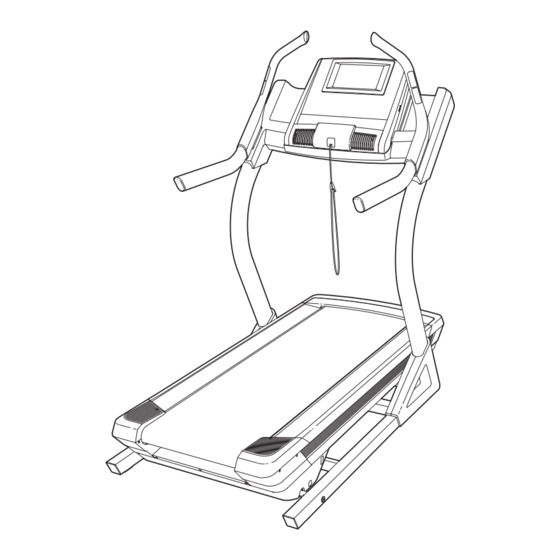
Apply the decal in the location shown. Note: The decals may not be shown at actual size. NORDICTRACK is a registered trademark of ICON IP, Inc. 271317... -
Page 3: Important Precautions
14. To water. purchase a surge suppressor, see your local NORDICTRACK dealer, call the telephone 6. Place the incline trainer on a level surface, number on the front cover of this manual, or with at least 8 ft. (2.4 m) of clearance behind see your local electronics store. - Page 4 17. Read, understand, and test the emergency ASSEMBLY on page 7, and HOW TO MOVE stop procedure before using the incline THE INCLINE TRAINER on page 26.) You must trainer (see HOW TO TURN ON THE POWER be able to safely lift 45 lbs. (20 kg) to raise, on page 16).
-
Page 5: Before You Begin
BEFORE YOU BEGIN Thank you for selecting the revolutionary reading this manual, please see the front cover of this NORDICTRACK INCLINE TRAINER X11i manual. To help us assist you, note the product model ® INTERACTIVE. The INCLINE TRAINER X11i number and serial number before contacting us. The... -
Page 6: Part Identification Chart
PART IDENTIFICATION CHART Use the drawings below to identify small parts used for assembly. The number in parentheses below each draw- ing is the key number of the part, from the PART LIST near the end of this manual. The number following the key number is the quantity used for assembly. -
Page 7: Assembly
• Left parts are marked “L” or “Left” and right parts or smartphone to read are marked “R” or “Right.”... - Page 8 2. Attach the Upright (77) to the Base (80) with two 3/8" x 5 1/2" Screws (5) and a 3/8" x 2 3/4" Screw (17) with three 3/8" Star Washers (8) as shown. Start all three Screws, and then tighten them. Make sure not to pinch the Upright Wire (not shown) in the Upright.
- Page 9 4. Have a second person hold the console assem- bly near the Uprights (77). Insert the console wire and the “R” pulse wire from the console assembly through the indicated tie. Connect the Upright Wire (78) to the console wire. See the inset drawing. The connectors should slide together easily and snap into place.
- Page 10 6. Tighten two #8 x 3/4" Screws (1) into the Console Base (87). Do not overtighten the Screws. Identify the Right Handrail Assembly (93). Hold the Right Handrail Assembly near the right Upright (77). Insert the pulse wire from the Right Handrail Assembly into the hole in the top of the Upright and pull it out of the end of the Upright.
- Page 11 8. Hold the Left Handrail Assembly (86) near the left Upright (77). Insert the pulse wire from the Left Handrail Assembly into the hole in the top of the Upright and pull it out of the end of the Upright. Set the Left Handrail Assembly (86) on the left Upright (77).
- Page 12 10. See page 14 and plug in the power cord. Next, see page 16 and turn on the power. Then, touch the 1 Step Incline button numbered 40 on the console. The Frame (58) will adjust to an incline of 40 percent. Then, turn off the incline trainer and unplug the power cord.
-
Page 13: The Chest Heart Rate Monitor
THE CHEST HEART RATE MONITOR HOW TO PUT ON THE HEART RATE MONITOR • Do not expose the heart rate monitor to direct sun- light for extended periods of time; do not expose it The heart rate to temperatures above 122° F (50° C) or below 14° monitor consists of F (-10°... -
Page 14: Operation And Adjustment
OPERATION AND ADJUSTMENT HOW TO CONNECT THE POWER CORD nominal 120-volt circuit capable of carrying 15 or more amps. To avoid overloading the circuit, do Use a Surge Suppressor not plug other electrical devices, except for low- power devices such as cell phone chargers, into Your incline trainer, like other electronic equipment, the surge suppressor or into an outlet on the same circuit. - Page 15 CONSOLE DIAGRAM FEATURES OF THE CONSOLE As you exercise, the console will display instant exer- cise feedback. You can also measure your heart rate The incline trainer console offers an impressive array using the handgrip heart rate monitor or the chest heart of features designed to make your workouts more rate monitor.
- Page 16 HOW TO TURN ON THE POWER HOW TO USE THE TOUCH SCREEN IMPORTANT: If the incline trainer has been The console features a tablet with a full-color touch exposed to cold temperatures, allow it to warm to screen. The following information will help you become room temperature before you turn on the power.
- Page 17 HOW TO SET UP THE CONSOLE The browser will open to the iFit.com registration page. Touch the Buy Now button to register for an Before using the incline trainer for the first time, set up iFit account. If you have an activation code, select the console.
- Page 18 HOW TO USE THE MANUAL MODE Note: The first time you adjust the incline, you must first calibrate the incline system (see step 4 on 1. Insert the key into the console. page 24). 5. Monitor your progress. See HOW TO TURN ON THE POWER on page 16.
- Page 19 rate will be shown. For the most accurate heart The displays at the top of the screen can show two types of information. Touch each display until the rate reading, continue to hold the contacts for display shows the desired information. about 15 seconds.
- Page 20 HOW TO USE AN ONBOARD WORKOUT If the speed and/or incline settings are too high or too low at any time during the workout, you can 1. Insert the key into the console. override the settings by pressing the Speed or Incline buttons.
- Page 21 HOW TO USE A SET-A-GOAL WORKOUT The workout will function in the same way as the manual mode (see pages 18 and 19). 1. Insert the key into the console. The workout will continue until you reach the goal See HOW TO TURN ON THE POWER on page 16. that you set.
- Page 22 HOW TO USE AN IFIT WORKOUT Before some workouts will download, you must add them to your schedule on iFit.com. Note: To use an iFit workout, you must have access For more information about the iFit workouts, to a wireless network (see HOW TO USE THE please see www.iFit.com.
- Page 23 HOW TO USE THE EQUIPMENT SETTINGS MODE 7. Turn on or turn off the display demo mode. The console features an equipment settings mode that The console features a display demo mode, allows you to change various console settings. designed to be used if the incline trainer is dis- played in a store.
- Page 24 To avoid damaging the incline trainer, do not Note: If a passcode is enabled, the console will regularly ask for you to enter the passcode. The turn off the power or remove the key while the console will remain locked until the correct pass- firmware is being updated.
- Page 25 HOW TO USE THE WIRELESS NETWORK MODE To use the keyboard, see HOW TO USE THE TOUCH SCREEN on page 16. The console features a wireless network mode that allows you to set up a wireless network connection. When the console is connected to your wireless network, the WiFi menu option at the top of the 1.
-
Page 26: How To Move The Incline Trainer
To enter a different web address in the URL bar, first, Plug one end of your audio cable into the audio jack slide your finger down the screen to view the URL bar, on the side of the console. Plug the other end into a if necessary. -
Page 27: Troubleshooting
TROUBLESHOOTING Most incline trainer problems can be solved by fol- c. Remove the key from the console, and then lowing the simple steps below. Find the symptom reinsert it. that applies, and follow the steps listed. If further assistance is needed, see the front cover of this d. - Page 28 SYMPTOM: The walking belt slows when walked on SYMPTOM: The walking belt is off-center or slips when walked on a. Use only a surge suppressor that meets all of the a. If the walking belt is off-center, first adjust specifications described on page 14. the incline to 40 percent.
-
Page 29: Exercise Guidelines
EXERCISE GUIDELINES Burning Fat—To burn fat effectively, you must exer- WARNING: cise at a low intensity level for a sustained period of Before beginning this time. During the first few minutes of exercise, your or any exercise program, consult your physi- body uses carbohydrate calories for energy. -
Page 30: Part List
PART LIST Model No. NTL24012.0 R1012A Key No. Qty. Description Key No. Qty. Description #8 x 3/4" Screw Reed Switch #8 x 3/4" Tek Screw Reed Switch Clamp Left Inside Cover Axle 5/16" x 2 1/2" Screw Frame 3/8" x 5 1/2" Screw Electronics Cover 3/8"... -
Page 31: Exploded Drawing
EXPLODED DRAWING A Model No. NTL24012.0 R1012A... - Page 32 EXPLODED DRAWING B Model No. NTL24012.0 R1012A...
- Page 33 EXPLODED DRAWING C Model No. NTL24012.0 R1012A...
- Page 34 EXPLODED DRAWING D Model No. NTL24012.0 R1012A...
- Page 35 EXPLODED DRAWING E Model No. NTL24012.0 R1012A...
-
Page 36: Ordering Replacement Parts
ORDERING REPLACEMENT PARTS To order replacement parts, please see the front cover of this manual. To help us assist you, be prepared to pro- vide the following information when contacting us: • the model number and serial number of the product (see the front cover of this manual) • the name of the product (see the front cover of this manual) • the key number and description of the replacement part(s) (see the PART LIST and the EXPLODED DRAWING near the end of this manual)
Need help?
Do you have a question about the Incline Trainer X11 and is the answer not in the manual?
Questions and answers
My i11 incline trainer about 6 months ago began to shut off during the middle of a workout. I would unplug it and replug and it worked fine. I also bought a new key for it. It worked well until a few weeks ago and it did it again. I reset again and now it does not come on at all. I bought it in 2010 and it has been great. I just replace the reset button and still no power. Would you please give some idea of what may be wrong and what part may need to be replaced. Thank you
The NordicTrack Incline Trainer X11 may shut off during workouts and not power on after resetting due to the following reasons:
1. Tripped Reset Button – If the machine shuts off, check if the reset button (interruptor) has tripped. Wait five minutes before pressing it back in to reset.
2. Power Cord Connection – Ensure the power cord is properly plugged into a surge suppressor and that the surge suppressor is connected to a grounded outlet.
3. Firmware Issues – If the iFit function is not working correctly, ensure the incline trainer has the latest firmware update.
4. Wireless Network Issues – If the machine is not connecting to Wi-Fi, check that the network settings are correct.
If the issue persists after checking these steps, refer to the manual cover for further assistance.
This answer is automatically generated