
Subscribe to Our Youtube Channel
Related Manuals for KTM 990 ADVENTURE EU


Summary of Contents for KTM 990 ADVENTURE EU
- Page 1 OWNER'S MANUAL 2012 990 Adventure EU 990 Adventure AUS/UK 990 Adventure FR 990 Adventure R EU 990 Adventure R AUS/UK Art. no. 3211791en...
- Page 3 KTM accepts no liability for delivery options, deviations from illustrations and descriptions, as well as misprints and other errors.
- Page 4 DEAR KTM CUSTOMER ISO 9001(12 100 6061) According to the international quality management standard ISO 9001, KTM uses quality assurance processes that lead to the maximum possible quality of the products. Issued by: TÜV Management Service KTM-Sportmotorcycle AG 5230 Mattighofen, Austria...
-
Page 5: Table Of Contents
TABLE OF CONTENTS Combination instrument - display........26 TABLE OF CONTENTS MEANS OF REPRESENTATION ..........7 Combination instrument - speedometer....... 27 IMPORTANT INFORMATION ........... 8 Setting kilometers or miles ..........27 VIEW OF VEHICLE..............12 Combination instrument - time .......... 28 View of vehicle, front left side (vehicle differs slightly from photo) ................ - Page 6 TABLE OF CONTENTS Side stand ............... 43 SERVICE WORK ON THE CHASSIS ........76 Center stand ..............44 Raising the vehicle using the center stand ......76 PREPARING FOR USE ............45 Raising the vehicle off of the center stand ......77 Information on first use.............
- Page 7 TABLE OF CONTENTS Changing the fuses in the fuse box........133 Installing the underride guard ........100 Removing the headlight mask with the headlight ....136 BRAKES ................101 Installing the headlight mask with the headlight ....137 ABS/antilock brake system (990 Adventure)...... 101 Changing the low beam bulb..........
- Page 8 TABLE OF CONTENTS STANDARDS..............214 Installing the oil filter ..........170 INDEX ................215 Filling up with engine oil ..........170 Adding engine oil ............172 CLEANING, CARE .............. 174 Cleaning motorcycle ............174 Checks and maintenance steps for winter operation ... 176 STORAGE ................
-
Page 9: Means Of Representation
All work marked with this symbol requires specialist knowledge and technical understanding. In the interest of your own safety, have these jobs performed by an authorized KTM workshop! There, your motorcycle will be serviced opti- mally by specially trained experts using the specialist tools required. -
Page 10: Important Information
Warranty The work prescribed in the service schedule must be carried out by an authorized KTM workshop only and confirmed in the customer's service record and in the KTM dealer.net; otherwise, all warranty claims will be void. No warranty claims can be considered for damage resulting from manipulations and/or alterations to the vehicle. - Page 11 Spare parts, accessories For your own safety, only use spare parts and accessory products that have been approved and/or recommended by KTM and have them installed by an authorized KTM workshop. KTM accepts no liability for other products and any resulting damage.
- Page 12 IMPORTANT INFORMATION – Switch off the engine and remove the ignition key. – Secure the motorcycle against falling over or rolling away using straps or other suitable devices. Environment Motorcycling is a wonderful sport and we naturally hope that you can enjoy it to the full. However, it can also lead to problems with the environment and conflict with other persons.
- Page 13 IMPORTANT INFORMATION Grades of risks Danger Identifies a danger that will immediately and invariably lead to fatal or serious permanent injury if the appropriate measures are not taken. Warning Identifies a danger that is likely to lead to fatal or serious injury if the appropriate measures are not taken. Caution Identifies a danger that may lead to minor injuries if the appropriate measures are not taken.
-
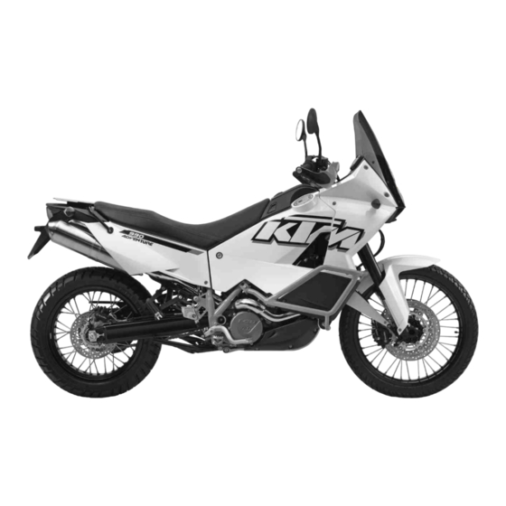
Page 14: View Of Vehicle
VIEW OF VEHICLE View of vehicle, front left side (vehicle differs slightly from photo) B00889-10... - Page 15 VIEW OF VEHICLE Clutch lever ( p. 19) Tool set ( p. 39) Seat lock ( p. 39) Luggage rack plate ( p. 41) Handrails ( p. 41) Fork compression adjustment Fuel taps ( p. 40) Side stand ( p. 43) Shift lever ( p.
-
Page 16: View Of Vehicle, Rear Right Side (Vehicle Differs Slightly From Photo)
VIEW OF VEHICLE View of vehicle, rear right side (vehicle differs slightly from photo) B00890-10... - Page 17 VIEW OF VEHICLE Storage compartment Light switch ( p. 20) Turn signal switch ( p. 21) Horn button ( p. 21) Headlight flasher switch ( p. 20) Hazard warning flasher switch/hazard warning flasher ( p. 34) Socket for electrical accessories ( p.
-
Page 18: Serial Numbers
SERIAL NUMBERS Chassis number The chassis number is stamped on the right side of the steering head. The chassis number is also found on the type label. 100542-10 Type label The type label is located on the right frame tube in the vicinity of the oil tank. B00891-10... -
Page 19: Engine Number
SERIAL NUMBERS Engine number The engine number is stamped on the left side of the engine under the engine sprocket. 100544-10 Key number The key number Code number can be found on the KEYCODECARD. Info You need the key number to order a spare key. Keep the KEYCODECARD in a safe place. -
Page 20: Fork Part Number
SERIAL NUMBERS Fork part number The fork part number is stamped on the inner side of the fork stub. 100545-10 Shock absorber part number The shock absorber part number is stamped on the upper part of the shock absorber. 100546-10... -
Page 21: Controls
CONTROLS Clutch lever The clutch lever is fitted on the left side of the handlebar. The clutch is hydraulically operated and self-adjusting. 100505-10 Hand brake lever The hand brake lever is fitted on the right side of the handlebar. The front brake is engaged using the hand brake lever. 100506-10... -
Page 22: Light Switch
CONTROLS Light switch The light switch is fitted on the left side of the handlebar. Possible states Low beam on – The light switch is turned downwards. In this position, the low beam and tail light are switched on. High beam on – The light switch is turned upwards. In this position, the high beam and tail light are switched on. -
Page 23: Turn Signal Switch
CONTROLS Turn signal switch The turn signal switch is fitted on the left side of the handlebar. Possible states Turn signal off Turn signal, left, on – The turn signal switch is pressed to the left. The turn signal switch automatically returns to the central position after use. Turn signal, right, on –... -
Page 24: Emergency Off Switch
CONTROLS Emergency OFF switch The emergency OFF switch is fitted on the right side of the handlebar. Possible states Emergency OFF switch off – In this position, the ignition circuit is inter- rupted, a running engine stops, and the engine cannot be started. Emergency OFF switch on –... -
Page 25: Ignition/Steering Lock
CONTROLS Ignition/steering lock The ignition/steering lock is in front of the upper triple clamp. Info The ignition may only be switched on using a black ignition key. Use the orange programming key to activate and deactivate the black ignition key. Possible states Ignition OFF –... -
Page 26: Combination Instrument
The second black ignition key is activated when the vehicle is shipped. Two additional spare ignition keys (key number on the KEYCODECARD) can be ordered from an authorized KTM workshop, but they must be activated before use. Combination instrument 5.11 The combination instrument is installed in front of the handlebar. -
Page 27: Combination Instrument - Tachometer
CONTROLS Combination instrument - tachometer 5.13 The tachometer shows the engine speed in revolutions per minute. The red marking shows the overspeed range of the engine. 400916-10 Combination instrument - indicator lamps 5.14 The indicator lamps offer additional information about the operating state of the motorcy- cle. -
Page 28: Combination Instrument - Display
CONTROLS The oil pressure warning lamp lights up red – The oil pressure is too low. FI warning lamp (MIL) lights up/flashes orange – The OBD (on-board diagno- sis) has detected an emission- or safety-critical error. The immobilizer indicator lamp lights up or flashes red – Status or error message for immobilizer/alarm system. -
Page 29: Combination Instrument - Speedometer
CONTROLS LEnGth Following the display function test, the wheel circumference LEnGth is shown for one sec- ond. Info 2205 mm equals the circumference of the 21" front wheel with a series production tire. The display then changes to the last selected mode. 400837-01 Combination instrument - speedometer 5.16... -
Page 30: Combination Instrument - Time
CONTROLS Condition The motorcycle is standing. – Switch on the ignition by turning the black ignition key to the position ON – Press the MODE button repeatedly until the ODO mode is active. – Keep the MODE button pressed until the display mode changes from km/h to mph or from mph to km/h. -
Page 31: Setting The Clock
CONTROLS Setting the clock 5.19 Condition The motorcycle is standing. – Switch on the ignition by turning the black ignition key to the position ON – Press the MODE button repeatedly until the ODO mode is active. – Keep the MODE button and the SET button pressed simultaneously. The time display begins to flash. -
Page 32: Combination Instrument - Setting/Resetting Trip 1
CONTROLS Combination instrument - setting/resetting TRIP 1 5.21 Info The TRIP 1 trip counter is always running and counts up to 999.9. The trip counter can be used to measure the distance covered during trips or between two refueling stops. After the value 999.9 is reached, the trip counter starts at 0.0 again. -
Page 33: Combination Instrument - Trip F Display
CONTROLS – Switch on the ignition by turning the black ignition key to the position ON – Press the MODE button repeatedly until the TRIP 2 mode is active. – Keep the SET button pressed. The TRIP 2 display is set to 0.0. 400841-01 Combination instrument - TRIP F display 5.23... -
Page 34: Combination Instrument - Ambient Temperature Display
CONTROLS Combination instrument - ambient temperature display 5.24 The ambient temperature is displayed in °C or °F. 400893-13 Setting the temperature unit of measure 5.25 Condition The motorcycle is standing. – Switch on the ignition by turning the black ignition key to the position ON –... -
Page 35: Combination Instrument - Warning Of Slippery Roads
CONTROLS Combination instrument - warning of slippery roads 5.26 The ice symbol lights up to indicate an increased danger of slippery roads. The ice symbol appears in the display when the ambient temperature drops below the specified value. Temperature 3 °C (37 °F) The ice symbol goes out in the display when the ambient temperature rises above the specified value again. -
Page 36: Hazard Warning Flasher Switch/Hazard Warning Flasher
CONTROLS Hazard warning flasher switch/hazard warning flasher 5.28 The hazard warning flasher switch is found to the left of the combination instrument. The hazard warning flasher is used to indicate emergency situations. Info The hazard warning flasher can be activated or deactivated while the ignition is switched on or up to 30 seconds after the ignition is switched off. -
Page 37: Opening The Filler Caps
CONTROLS Opening the filler caps 5.30 Danger Fire hazard Fuel is highly flammable. – Never refuel the vehicle near open flames or burning cigarettes, and always switch off the engine first. Be careful that no fuel is spilt, especially on hot vehicle components. Clean up spilt fuel immediately. –... -
Page 38: Closing The Filler Caps
CONTROLS – Remove the ignition key. Info The motorcycle is equipped with two fuel tanks and two filler necks. The fuel tanks are connected to each other with a fuel line that equalizes the fuel level. The two filler caps are equipped with a ventilation system. Closing the filler caps 5.31 Warning... -
Page 39: Unlocking The Storage Compartment
CONTROLS Unlocking the storage compartment 5.32 – Insert the ignition key into the seat lock. – Turn the ignition key to position – Remove the ignition key. 100518-10 Locking the storage compartment 5.33 – Insert the ignition key into the seat lock. –... -
Page 40: Opening The Storage Compartment
CONTROLS Opening the storage compartment 5.34 – Unlock the storage compartment. ( p. 37) – Press button toward the seat and raise the cover at the same time. Info The storage compartment can only be opened if it was first unlocked using the seat lock. -
Page 41: Seat Lock
CONTROLS Seat lock 5.36 The seat lock is located in the left side cover below the seat. The seat lock unlocks the seat and locks and unlocks the storage compartment. Possible states • Storage compartment locked • Storage compartment unlocked •... -
Page 42: Passenger Footrests
CONTROLS Passenger footrests 5.38 The passenger footrests can be folded up and down. Possible states Passenger footrests folded up – For operation without a passenger. • Passenger footrests folded down – For operation with a passenger. • 100530-10 Fuel taps 5.39 There is a fuel tap on every fuel tank. -
Page 43: Handrails
CONTROLS Handrails 5.40 The handrails are used for moving the motorcycle around. When you have a passenger, the passenger can hold on the handrails during the trip. B00553-10 Luggage rack plate 5.41 The luggage rack plate is located behind the seat. The base plate of a luggage system (optional) can be attached to the luggage rack plate. -
Page 44: Shift Lever
CONTROLS Shift lever 5.42 Shift lever is mounted on the left side of the engine. 100526-10 The gear positions can be seen in the photograph. The neutral or idle position is between the first and second gears. 100527-10... -
Page 45: Foot Brake Lever
CONTROLS Foot brake lever 5.43 Foot brake lever is located in front of the right footrest. The rear brake is activated using the foot brake lever. 100525-10 Side stand 5.44 The side stand is located on the left side of the vehicle. The side stand is used for parking the motorcycle. -
Page 46: Center Stand
CONTROLS Center stand 5.45 The vehicle is equipped with a center stand in addition to a side stand. 100529-10... -
Page 47: Preparing For Use
The front and rear wheels must be fitted with tires with similar tread patterns to prevent loss of control over the vehicle. Warning Danger of accidents Uncontrollable handling characteristic due to non-approved and/or non-recommended tires/wheels. – Only tires/wheels approved by KTM and with the corresponding speed index should be used. Warning Danger of accidents Reduced road grip with new tires. –... -
Page 48: Running In The Engine
When using your vehicle, remember that others may feel disturbed by excessive noise. – Make sure that the pre-delivery inspection work has been carried out by an authorized KTM workshop. You receive a delivery certificate and the service record at vehicle handover. -
Page 49: Loading The Vehicle
PREPARING FOR USE – Avoid full-throttle operation! Loading the vehicle Warning Danger of accidents Unstable handling characteristics. – Do not exceed the maximum permitted weight and axle loads. The overall weight consists of: motorcycle operational and with a full tank, driver and passenger with protective clothing and helmet, baggage. Warning Danger of accidents Unstable handling characteristics due to incorrect mounting of suitcase and/or tank rucksack. - Page 50 PREPARING FOR USE Warning Danger of accidents Unstable handling characteristics due to slipped baggage. – Check the way your baggage is fixed regularly. Warning Danger of burns A hot exhaust system can burn baggage. – Fasten your baggage in such a way that it cannot be burned or singed by the hot exhaust system. –...
-
Page 51: Riding Instructions
RIDING INSTRUCTIONS Checks and maintenance measures when preparing for use Info Before every trip, check the condition of the vehicle and ensure that it is roadworthy. The vehicle must be in perfect technical condition when it is being operated. – Check the engine oil level. -
Page 52: Starting
RIDING INSTRUCTIONS Starting Danger Danger of poisoning Exhaust gases are poisonous and inhaling them may result in unconsciousness and/or death. – When running the engine, always make sure there is sufficient ventilation, and do not start or run the engine in an enclosed space without an effective exhaust extraction system. - Page 53 RIDING INSTRUCTIONS – Turn the emergency OFF switch to the position – Switch on the ignition by turning the black ignition key to the position ON After you switch on the ignition, you can hear the fuel pump working for about two seconds.
-
Page 54: Starting Off
RIDING INSTRUCTIONS Switching off ABS (990 Adventure) KTM recommends riding with ABS at all times. However, situations may arise in which ABS is not advantageous. Condition Vehicle is standing, engine is running. – Press button for 3 - 5 seconds. - Page 55 RIDING INSTRUCTIONS Warning Danger of accidents Distraction from traffic activity by adjustments to the vehicle. – Make all adjustments when the vehicle is at a standstill. Warning Risk of injury Falling off of the passenger. – The passenger must be capable of properly holding onto the driver or the grab handles and of keeping his or her feet on the passenger footrests.
- Page 56 If you continue with the coolant temperature warning lamp alight, you may have engine failure. Info If you hear unusual noises while riding, stop immediately, switch off the engine and contact an authorized KTM workshop.
- Page 57 RIDING INSTRUCTIONS – When conditions allow (incline, road situation, etc.), you can shift into a higher gear. – Release the throttle while simultaneously pulling the clutch lever, shift into the next gear, release the clutch and open the throttle. Info You can see the positions of the six forward gears in the figure.
-
Page 58: Braking
Danger of accidents Reduced braking efficiency caused by spongy pressure point of front or rear brake. – Check the brake system and do not continue riding. (Your authorized KTM workshop will be glad to help.) Warning Danger of accidents Failure of brake system. - Page 59 RIDING INSTRUCTIONS Warning Danger of accidents Excessively hard braking causes the wheels to lock. – ABS must be switched on to be effective. – When braking, first throttle back and then apply the front and rear brakes at the same time. Info ABS lets you apply the brakes fully during emergency braking and in situations where road grip is compromised, such as on sandy, wet or slippery surfaces, without the danger of the wheels locking.
-
Page 60: Stopping, Parking
RIDING INSTRUCTIONS – On long downhill stretches, use the braking effect of the engine. Do this by changing down two gears, but do not race the engine. You will require less braking force and the brakes will not overheat. Stopping, parking Warning Risk of misappropriation Usage by unauthorized persons. - Page 61 RIDING INSTRUCTIONS Note Material damage Damage and destruction of components from excessive load. – The center stand is only designed for the weight of the motorcycle and luggage. Do not sit on the motorcycle while it is resting on the center stand. The center stand or frame could be damaged and the motorcycle could fall over. –...
-
Page 62: Refueling
– In some countries and regions, the available fuel quality and cleanliness may not be sufficient. This will result in problems with the fuel system. (Your authorized KTM workshop will be glad to help.) – Only refuel with clean fuel that meets the specified standards. - Page 63 RIDING INSTRUCTIONS – Switch off the engine. – Lean the vehicle on the side stand. – Open the filler caps. ( p. 35) – Fill the right fuel tank with fuel no higher than level Guideline Measurement of 75 mm (2.95 in) –...
- Page 64 RIDING INSTRUCTIONS – Press the SET button for two seconds. The fuel level warning lamp switches off. TRIP F is set to 0.0 and the previous display mode appears. Info If you do not press the SET button , the reset takes place automatically after about three minutes.
-
Page 65: Service Schedule
Check that the electrical equipment is functioning properly. • • • • • • • • Read out the trouble code memory using the KTM diagnostics tool. • • • Check the measured service values with the KTM diagnostics tool. • • • •... - Page 66 Change the air filter. Clean the air filter box. Check the fuel pressure. • • • Check the value of the manifold absolute pressure sensor (PM value) with the KTM diagnostics • • • tool. Check the CO adjustment with the KTM diagnostics tool.
- Page 67 • • • • • • Read out the error memory after the test ride using the KTM diagnostics tool. • • • • Make the necessary service entries in the KTM DEALER.NET and service record. K10N: Once after 1,000 km (621.4 mi)
-
Page 68: Tuning The Chassis
TUNING THE CHASSIS Fork/shock absorber The fork and the shock absorber offer many options of adapting the suspension to your rid- ing style and the payload. Info To help you adapt the vehicle, we have summarized our findings in Table . -
Page 69: Adjusting The Rebound Damping Of The Fork
TUNING THE CHASSIS Guideline (990 Adventure) Compression damping Comfort 20 clicks Standard 15 clicks Sport 10 clicks Full payload 10 clicks (990 Adventure R) Compression damping Comfort 20 clicks Standard 15 clicks Sport 10 clicks Full payload 10 clicks Info Turn clockwise to increase damping;... - Page 70 TUNING THE CHASSIS – Turn adjusting screws clockwise all the way. Info The adjusting screws are located at the top end of the fork legs. Make the same adjustment on both fork legs. – Turn back counterclockwise by the number of clicks corresponding to the fork type. Guideline (990 Adventure) Rebound damping...
-
Page 71: Adjusting The Spring Preload Of The Fork
TUNING THE CHASSIS Adjusting the spring preload of the fork – Turn adjusting screws counterclockwise all the way. Info Make the same adjustment on both fork legs. – Turn back clockwise by the number of turns corresponding to the fork type. Guideline (990 Adventure) Spring preload - Preload Adjuster... -
Page 72: Compression Damping Of The Shock Absorber
Caution Danger of accidents Disassembly of pressurized parts can lead to injury. – The shock absorber is filled with high density nitrogen. Adhere to the description provided. (Your authorized KTM workshop will be glad to help.) Info The low-speed setting can be seen during the slow to normal compression of the shock absorber. - Page 73 TUNING THE CHASSIS – Turn adjusting screw clockwise with a screwdriver up to the last perceptible click. Info Do not loosen nut – Turn back counterclockwise by the number of clicks corresponding to the shock absorber type. Guideline (990 Adventure) Compression damping, low-speed 100537-10 Comfort...
-
Page 74: Adjusting The High-Speed Compression Damping Of The Shock Absorber
Caution Danger of accidents Disassembly of pressurized parts can lead to injury. – The shock absorber is filled with high density nitrogen. Adhere to the description provided. (Your authorized KTM workshop will be glad to help.) Info The high-speed setting can be seen during the fast compression of the shock absorber. -
Page 75: Adjusting The Rebound Damping Of The Shock Absorber
Adjusting the rebound damping of the shock absorber Caution Danger of accidents Disassembly of pressurized parts can lead to injury. – The shock absorber is filled with high density nitrogen. Adhere to the description provided. (Your authorized KTM workshop will be glad to help.) – Turn adjusting screw clockwise up to the last perceptible click. -
Page 76: Adjusting The Spring Preload Of The Shock Absorber
Adjusting the spring preload of the shock absorber Caution Danger of accidents Disassembly of pressurized parts can lead to injury. – The shock absorber is filled with high density nitrogen. Adhere to the description provided. (Your authorized KTM workshop will be glad to help.) - Page 77 TUNING THE CHASSIS – Turn handwheel counterclockwise as far as it will go. – Turn it clockwise by the number of turns corresponding to the shock absorber type and use. Guideline (990 Adventure) Spring preload - Preload Adjuster Comfort 4 turns Standard 4 turns 100549-10...
-
Page 78: Service Work On The Chassis
SERVICE WORK ON THE CHASSIS Raising the vehicle using the center stand 10.1 Note Danger of damage The parked vehicle may roll away or fall over. – Always place the vehicle on a firm and even surface. Note Material damage Damage and destruction of components from excessive load. –... -
Page 79: Raising The Vehicle Off Of The Center Stand
SERVICE WORK ON THE CHASSIS Raising the vehicle off of the center stand 10.2 Note Danger of damage The parked vehicle may roll away or fall over. – Always place the vehicle on a firm and even surface. – Unlock the steering and move the vehicle forward with both hands on the handlebar. –... -
Page 80: Cleaning The Dust Boots Of The Fork Legs
SERVICE WORK ON THE CHASSIS Main work – Remove bleeder screws briefly. Any excess pressure escapes from the interior of the fork. – Mount and tighten the bleeder screws. Info Carry out this operation on both fork legs. 100536-10 Cleaning the dust boots of the fork legs 10.4 Preliminary work –... -
Page 81: Checking The Steering Head Bearing Play
Danger of accidents Unstable vehicle handling from incorrect steering head bearing play. – Adjust the steering head bearing play without delay. (Your authorized KTM workshop will be glad to help.) Info If the vehicle is operated for a lengthy period with play in the steering head bearing, the bearings and the bearing seats in the frame can become damaged over time. -
Page 82: Removing The Front Side Cover
SERVICE WORK ON THE CHASSIS – Move the handlebar to and fro over the entire steering range. It must be possible to move the handlebar easily over the entire steering range. There should be no detectable detent positions. » If detent positions are detected: –... -
Page 83: Removing The Radiator Guard
SERVICE WORK ON THE CHASSIS – Position side cover at the fuel tank on the bottom and hold it at an angle. – Attach the overflow hose of the fuel tank to the connector. – Connect the plug-in connectors of the turn signal cables and swing the side cover up toward the vehicle. -
Page 84: Installing The Radiator Guard
SERVICE WORK ON THE CHASSIS – Pull nuts off of the radiator. Insert the screws into the holes of the radiator guard and mount the nuts. This ensures that all required parts are available when needed. 100642-10 Installing the radiator guard 10.9 –... -
Page 85: Removing The Seat
SERVICE WORK ON THE CHASSIS Removing the seat 10.10 – Insert the ignition key into the seat lock. – Turn the ignition key to position – Lift up the seat at the rear, pull it back and remove from above. –... -
Page 86: Removing The Crash Bar (990 Adventure)
SERVICE WORK ON THE CHASSIS Removing the crash bar (990 Adventure) 10.12 Info The operations are the same for the left and right sides. Preliminary work – Raise the vehicle using the center stand. ( p. 76) Main work – Remove screw 101563-10 –... -
Page 87: Installing The Crash Bar (990 Adventure)
SERVICE WORK ON THE CHASSIS Installing the crash bar (990 Adventure) 10.13 Info The operations are the same for the left and right sides. Main work – Position the crash bar and attach the clamp to the frame tube. – Mount screws but do not tighten yet. -
Page 88: Removing The Storage Compartment And Hanging It To One Side
SERVICE WORK ON THE CHASSIS Removing the storage compartment and hanging it to one side 10.14 Preliminary work – Remove the seat. ( p. 83) Main work – Open the storage compartment. ( p. 38) – Remove screws – Carefully remove the storage compartment and swing it to the right. Place a cloth between the right fuel tank and the storage compartment to prevent damage. -
Page 89: Removing The Left Fuel Tank
SERVICE WORK ON THE CHASSIS Removing the left fuel tank 10.16 Danger Fire hazard Fuel is highly flammable. – Never refuel the vehicle near open flames or burning cigarettes, and always switch off the engine first. Be careful that no fuel is spilt, especially on hot vehicle components. -
Page 90: Installing The Left Fuel Tank
SERVICE WORK ON THE CHASSIS Main work – Remove screws – Lift the fuel tank slightly at the front, detach at the upper bracket and swing away from the vehicle at the top. Info Hold the fuel tank at roughly its installation height. Before it can be completely removed, several hoses and plug-in connections need to be detached. - Page 91 SERVICE WORK ON THE CHASSIS Warning Danger of poisoning Fuel is poisonous and a health hazard. – Avoid contact between fuel and skin, eyes and clothing. Do not inhale fuel vapors. If fuel gets into your eyes, rinse immediately with water and contact a doctor. Wash affected skin areas immediately with soap and water. If fuel is swallowed, contact a doc- tor immediately.
-
Page 92: Checking For Chain Dirt
SERVICE WORK ON THE CHASSIS Guideline Screw, fuel tank 15 Nm (11.1 lbf ft) Subsequent work – Install the storage compartment. p. 86) – Close the storage compartment. ( p. 38) – Mount the seat. ( p. 83) – Install the front side cover. ( p. -
Page 93: Cleaning The Chain
SERVICE WORK ON THE CHASSIS Cleaning the chain 10.19 Warning Danger of accidents Oil or grease on the tires reduces their grip. – Remove oil and grease with a suitable cleaning material. Warning Danger of accidents Reduced braking efficiency due to oil or grease on the brake discs. –... -
Page 94: Checking The Chain Tension
SERVICE WORK ON THE CHASSIS Checking the chain tension 10.20 Warning Danger of accidents Danger caused by incorrect chain tension. – If the chain tension is too high, the components of the secondary power train (chain, engine sprocket, rear sprocket, bearings in transmission and rear wheel) are under additional load. -
Page 95: Adjusting The Chain Tension
SERVICE WORK ON THE CHASSIS Adjusting the chain tension 10.21 Warning Danger of accidents Danger caused by incorrect chain tension. – If the chain tension is too high, the components of the secondary power train (chain, engine sprocket, rear sprocket, bearings in transmission and rear wheel) are under additional load. - Page 96 SERVICE WORK ON THE CHASSIS Main work – Loosen nut – Loosen nuts – Adjust the chain tension by turning the adjusting screws on the left and right. Guideline Chain tension 35… 40 mm (1.38… 1.57 in) Turn adjusting screws on the left and right so that the markings on the left and right chain adjuster are in the same position in relation to reference marks...
-
Page 97: Checking The Chain, Rear Sprocket And Engine Sprocket
SERVICE WORK ON THE CHASSIS Checking the chain, rear sprocket and engine sprocket 10.22 – Check the rear sprocket and engine sprocket for wear. » If the rear sprocket or engine sprocket is worn: – Change the rear sprocket or engine sprocket. Info The rear sprocket, engine sprocket and chain should always be changed together. - Page 98 SERVICE WORK ON THE CHASSIS – Raise the vehicle using the center stand. ( p. 76) – Shift the transmission to neutral. – Pull the lower chain section with specified weight Guideline Weight, chain wear measurement 15 kg (33 lb.) –...
- Page 99 SERVICE WORK ON THE CHASSIS – Check the chain sliding guard for wear. » If the chain sliding guard is worn: – Change the chain sliding guard. – Check the chain sliding guard for tightness. » If the chain sliding guard is loose: –...
-
Page 100: Adjusting The Basic Setting Of The Clutch Lever
SERVICE WORK ON THE CHASSIS Adjusting the basic setting of the clutch lever 10.23 – Adjust the basic setting of the clutch lever to your hand size by turning adjusting screw Info Turn the adjusting screw clockwise to increase the distance between the clutch lever and the handlebar. -
Page 101: Removing The Right Underride Guard
SERVICE WORK ON THE CHASSIS – Position the cover with the membrane. Mount and tighten the screws. Removing the right underride guard 10.25 – Remove screws . Remove the right underride guard 100581-10 Installing the right underride guard 10.26 – Position right underride guard . -
Page 102: Removing The Underride Guard X
SERVICE WORK ON THE CHASSIS Removing the underride guard 10.27 Preliminary work – Raise the vehicle using the center stand. ( p. 76) Main work – Swing the side stand downward. – Remove all four screws and take off underride guard 100577-10 Installing the underride guard 10.28... -
Page 103: Brakes
– The ABS will only function correctly if the spare parts used in the brake system and the tires have been approved and/or recommended by KTM. – Maintenance work and repairs must be carried out professionally. (Your autho- rized KTM workshop will be glad to help.) -
Page 104: Checking The Free Travel Of The Hand Brake Lever
BRAKES To reenable the ABS, the vehicle must be stopped and the ignition switched off. The ABS is reenabled when the vehicle is switched on again. The ABS warning lamp goes out when you start off. Button can be used to switch ABS off manually (see Starting). Checking the free travel of the hand brake lever 11.2 Warning... -
Page 105: Adjusting The Free Travel Of The Hand Brake Lever
Danger of accidents Reduced braking efficiency due to worn brake disc(s). – Change the worn brake disc(s) without delay. (Your authorized KTM workshop will be glad to help.) – Check the thickness of the front and rear brake discs in several places to ensure that it... -
Page 106: Checking The Front Brake Fluid Level
(Your authorized KTM workshop will be glad to help.) Warning Danger of accidents Reduced braking efficiency due to old brake fluid. – Change the brake fluid of the front and rear brake according to the service schedule. (Your authorized KTM workshop will be glad to help.) -
Page 107: Adding Front Brake Fluid
If brake fluid comes into contact with the eyes, flush the eyes thoroughly with water and consult a physician immediately. Warning Danger of accidents Reduced braking efficiency due to old brake fluid. – Change the brake fluid of the front and rear brake according to the service schedule. (Your authorized KTM workshop will be glad to help.) - Page 108 BRAKES Warning Environmental hazard Hazardous substances cause environmental damage. – Oil, grease, filters, fuel, cleaners, brake fluid, etc., should be disposed of as stipulated in applicable regulations. Info Never use DOT 5 brake fluid! It is silicone-based and purple in color. Oil seals and brake lines are not designed for DOT 5 brake fluid.
-
Page 109: Checking The Front Brake Linings
11.7 Warning Danger of accidents Reduced braking efficiency caused by worn brake linings. – Change worn brake linings immediately. (Your authorized KTM workshop will be glad to help.) Note Danger of accidents Reduced braking efficiency caused by damaged brake discs. – If the brake linings are not changed in time, the steel brake lining carriers grind on the brake disc. The braking effect is greatly reduced and the brake discs are rendered unserviceable. -
Page 110: Checking The Rear Brake Fluid Level
(Your authorized KTM workshop will be glad to help.) Warning Danger of accidents Reduced braking efficiency due to old brake fluid. – Change the brake fluid of the front and rear brake according to the service schedule. (Your authorized KTM workshop will be glad to help.) -
Page 111: Adding Rear Brake Fluid
If brake fluid comes into contact with the eyes, flush the eyes thoroughly with water and consult a physician immediately. Warning Danger of accidents Reduced braking efficiency due to old brake fluid. – Change the brake fluid of the front and rear brake according to the service schedule. (Your authorized KTM workshop will be glad to help.) - Page 112 BRAKES Warning Environmental hazard Hazardous substances cause environmental damage. – Oil, grease, filters, fuel, cleaners, brake fluid, etc., should be disposed of as stipulated in applicable regulations. Info Never use DOT 5 brake fluid! It is silicone-based and purple in color. Oil seals and brake lines are not designed for DOT 5 brake fluid.
-
Page 113: Checking The Rear Brake Linings
11.11 Warning Danger of accidents Reduced braking efficiency caused by worn brake linings. – Change worn brake linings immediately. (Your authorized KTM workshop will be glad to help.) Note Danger of accidents Reduced braking efficiency caused by damaged brake discs. – If the brake linings are not changed in time, the steel brake lining carriers grind on the brake disc. The braking effect is greatly... - Page 114 BRAKES – Check the brake linings for minimum thickness ≥ 1 mm (≥ 0.04 in) Minimum thickness » If the minimum thickness is less than specified: – Change the rear brake linings. – Check the brake linings for damage and cracking. »...
-
Page 115: Wheels, Tires
WHEELS, TIRES Removing the front wheel 12.1 Preliminary work – Raise the vehicle using the center stand. ( p. 76) Main work – Bear down on the rear of the vehicle or raise it on the underride guard. The front wheel is not in contact with the ground. –... - Page 116 WHEELS, TIRES – Loosen screws – Unscrew screw about six turns and press your hand on the screw to push the wheel spindle out of the axle clamp. Warning Danger of accidents Reduced braking efficiency due to damaged brake discs. – Always lay down the wheel in such a way that the brake discs are not dam- aged.
-
Page 117: Installing The Front Wheel
WHEELS, TIRES Installing the front wheel 12.2 Warning Danger of accidents Reduced braking efficiency due to oil or grease on the brake discs. – Always keep the brake discs free of oil and grease, and clean them with brake cleaner when necessary. –... -
Page 118: Removing The Rear Wheel
WHEELS, TIRES – Fully tighten screws Guideline Screw, fork stub 15 Nm (11.1 lbf ft) (990 Adventure) – Slide sleeve onto the wheel speed sensor and push them into the hole together. Mount and tighten screw Guideline Screw connection, wheel speed sensor, 6 Nm (4.4 lbf ft) front 100603-11... - Page 119 WHEELS, TIRES (990 Adventure) – Remove screw and pull wheel speed sensor out of the hole. 100635-10 – Remove nut . Remove chain adjuster 100569-10 – Pull out wheel spindle only far enough to allow the rear wheel to be pushed forward. –...
-
Page 120: Installing The Rear Wheel
WHEELS, TIRES – Holding the rear wheel, withdraw the wheel spindle. Take the rear wheel out of the swing arm. Info Do not operate the foot brake when the rear wheel is removed. – Remove the spacer Installing the rear wheel 12.4 Warning Danger of accidents Reduced braking efficiency due to oil or grease on the brake discs. - Page 121 WHEELS, TIRES – Mount the rubber dampers and rear sprocket carrier in the rear wheel. – Place the rear wheel in the swingarm and bring the brake disc on the brake caliper into contact. – Mount the wheel spindle but do not push it in all the way. –...
-
Page 122: Checking The Rear Hub Rubber Dampers
WHEELS, TIRES Checking the rear hub rubber dampers 12.5 Info The engine power is transmitted from the rear sprocket to the rear wheel via 6 rubber dampers. They eventually wear out during operation. If the rubber dampers are not changed in time, the rear sprocket carrier and the rear hub will be damaged. Preliminary work –... -
Page 123: Checking The Tire Condition
Danger of accidents Uncontrollable vehicle handling in the event of a flat tire. – In the interest of safety, replace damaged or worn tires immediately. (Your authorized KTM workshop will be glad to help.) Warning Danger of crashing Poor vehicle handling due to different tire tread patterns on front and rear wheels. -
Page 124: Checking The Tire Air Pressure
DOT marking. The first two digits refer to the week of manufacture and last two digits refer to the year of manufacture. KTM recommends that the tires be changed after 5 years at the latest, regard- less of the actual state of wear. -
Page 125: Checking Spoke Tension
Danger of accidents Instable handling due to incorrect spoke tension. – Ensure that the spoke tension is correct. (Your authorized KTM workshop will be glad to help.) Info A loose spoke can cause wheel imbalance, leading to more loose spokes in a short time. - Page 126 WHEELS, TIRES – Strike each spoke briefly using a screwdriver blade. Info The frequency of the sound is a function of the spoke length and spoke diame- ter. If spokes of the same length and diameter vibrate with a different tone, this is an indication that the spoke tensions differ.
-
Page 127: Electrical System
ELECTRICAL SYSTEM Removing the battery 13.1 Warning Risk of injury Battery acid and battery gases cause serious chemical burns. – Keep batteries out of the reach of children. – Wear suitable protective clothing and goggles. – Avoid contact with battery acid and battery gases. –... -
Page 128: Installing The Battery
ELECTRICAL SYSTEM – Disconnect the negative (minus) cable of the battery. – Disconnect the positive (plus) cable of the battery. – Take the battery out of the battery compartment with battery tray Info Never operate the motorcycle with a discharged battery or without a battery. In both cases, electrical components and safety equipment can be damaged. -
Page 129: Recharging The Battery
ELECTRICAL SYSTEM – Hook cover into the battery compartment at the bottom and swing up. – Mount and tighten screws 100579-11 Subsequent work – Install the underride guard. p. 100) – Raise the vehicle off of the center stand. ( p. - Page 130 The battery is maintenance-free, i.e., the acid level does not have to be checked. If the battery is not charged using the KTM battery charger, the battery must be removed for charging. Otherwise, overvoltage may damage electronic components. Charge the battery according to the instructions on the battery casing.
-
Page 131: Changing The Main Fuse
ELECTRICAL SYSTEM Main work – Pull off the red protection cap of the positive terminal extension. – Connect the positive cable of the charger to the positive terminal extension and the negative cable to an unpainted point on the engine . - Page 132 ELECTRICAL SYSTEM Info The main fuse is located in the starter relay under the right underride guard. Preliminary work – Switch off all power consumers and the engine. – Remove the right underride guard. ( p. 99) Main work – Pull starter relay off of the holder and remove protective cover 100583-10...
-
Page 133: Changing The Abs Fuses (990 Adventure)
ELECTRICAL SYSTEM Info A defective fuse can be identified by the burned-out fuse wire A reserve fuse is located in the starter relay. The main fuse protects all power consumers of the vehicle. – Install a new main fuse. Fuse (58011109130) ( p. - Page 134 ELECTRICAL SYSTEM Preliminary work – Switch off all power consumers and the engine. – Remove the right underride guard. ( p. 99) Changing the fuse of the ABS hydraulic unit: – Remove protective cover and remove fuse Info A spare fuse is located next to the fuse box in the storage compartment. –...
-
Page 135: Changing The Fuses In The Fuse Box
ELECTRICAL SYSTEM Place the spare fuse in the storage compartment so that it is available if needed. Follow-up work – Install the right underride guard. ( p. 99) Changing the fuses in the fuse box 13.6 Warning Fire hazard The electrical system can be overloaded if the wrong fuses are used. –... - Page 136 ELECTRICAL SYSTEM Main work – Remove fuse box cover 100587-10 – Remove the faulty fuse. Guideline Fuse IGNITION, FUEL PUMP - 10 A - ignition, fuel pump, immobilizer, alarm system (optional) Fuse H/L BEAM, POSITION - 15 A - high beam, low beam, parking light, license plate lamp Fuse HORN, BRAKE LIGHT - 10 A - horn, brake light, hazard warning flasher Fuse FAN - 10 A - radiator fan...
- Page 137 ELECTRICAL SYSTEM (990 Adventure) – Use spare fuses with the correct rating only. Fuse (58011109110) ( p. 196) Fuse (58011109115) ( p. 196) Info Spare fuses are located next to the fuse box. The spare fuses are for the ABS. 100588-10 Replace the spare fuse in the fuse box so that it is available if needed.
-
Page 138: Removing The Headlight Mask With The Headlight
ELECTRICAL SYSTEM Removing the headlight mask with the headlight 13.7 Preliminary work – Switch off all power consumers and the engine. – Remove the front side cover. ( p. 80) Main work – Unhook the headlight mask from the cockpit holder and remove it toward the front. 100590-10 –... -
Page 139: Installing The Headlight Mask With The Headlight
ELECTRICAL SYSTEM Installing the headlight mask with the headlight 13.8 Main work – Connect plug-in connector – Check the lighting function. – Position the headlight mask. 100591-10 Subsequent work – Install the front side cover. ( p. 80) – Check the headlight setting. ( p. - Page 140 ELECTRICAL SYSTEM Main work – Remove rubber cap and connector from the bulb. 100592-10 – Detach spring bar and remove the bulb from the headlight. – Position the new bulb in the headlight and attach the spring bar. Low beam (H7 / socket PX26d) ( p.
-
Page 141: Changing The High Beam Bulb
ELECTRICAL SYSTEM Changing the high beam bulb 13.10 Note Damage to reflector Reduced luminance. – Grease on the lamp will evaporate due to the heat and be deposited on the reflector. Clean the lamp and keep it free of grease before mounting. -
Page 142: Changing The Parking Light Bulb In The Headlight
ELECTRICAL SYSTEM – Detach spring bar and remove the bulb from the headlight. – Position the new bulb in the headlight and attach the spring bar. High beam (H3 / socket PK22s) ( p. 197) Info The bulb must be correctly seated at projections –... -
Page 143: Changing The Turn Signal Bulb
ELECTRICAL SYSTEM – Pull socket out of the headlight and pull bulb out of the socket. – Insert the new bulb into the socket and insert the socket into the headlight. Parking light (W5W / socket W2.1x9.5d) ( p. 197) 100596-10 Follow-up work –... -
Page 144: Changing The Tail Light Bulb
ELECTRICAL SYSTEM – Remove the screw on the rear of the turn signal housing. – Carefully remove diffuser – Press bulb carefully into the socket, turn it counterclockwise by about 30°, and pull it out of the socket. Info Do not touch the reflector with your fingers, and keep it free from grease. –... -
Page 145: Changing The Brake Light Bulb
ELECTRICAL SYSTEM – Remove nuts at the bottom of the rear fender and pull out the tail light toward the rear. 100599-10 – Pull bulb sockets out of the tail light. – Pull bulbs out of the sockets. – Insert new bulbs into the sockets. Tail light (WR5W / socket W2.1x9.5d) ( p. - Page 146 ELECTRICAL SYSTEM – Remove nuts at the bottom of the rear fender and pull out the tail light toward the rear. 100599-10 – Turn bulb socket counterclockwise all the way and take it out of the tail light. – Press bulb carefully into the socket, turn it counterclockwise by about 30°, and pull it out of the socket.
-
Page 147: Checking The Headlight Setting
ELECTRICAL SYSTEM Checking the headlight setting 13.15 – Park the vehicle on a horizontal surface in front of a light-colored wall and make a mark at the height of the center of the low beam headlight. 0 0 A – Make another mark at a distance of under the first mark. -
Page 148: Activating/Deactivating The Ignition Key
ELECTRICAL SYSTEM Main work – Turn adjusting screw to adjust the headlight range. Guideline For a motorcycle with rider, and with luggage and a passenger if applicable, the light/dark boundary must be exactly on the lower mark (applied in: Checking headlight adjustment). - Page 149 ELECTRICAL SYSTEM Loss of a black ignition key (second black ignition key available): The following procedure deactivates all activated black ignition keys that are not included in the procedure. – Turn the emergency OFF switch to the position 401114-10 – Insert the orange programming key in the ignition lock.
- Page 150 ELECTRICAL SYSTEM The immobilizer indicator lamp lights up, switches off briefly and flashes; the number of flashes equals the number of functional black ignition keys including the orange programming key. In this case, twice. – Switch off the ignition by turning the orange programming key to the OFF position –...
- Page 151 ELECTRICAL SYSTEM – Switch off the ignition by turning the orange programming key to the OFF position – Pull out the orange programming key. All black ignition keys are deactivated. – Order a new black ignition key according to the key number on the KEYCODECARD and activate it.
- Page 152 ELECTRICAL SYSTEM The immobilizer indicator lamp lights up, switches off briefly and flashes; the number of flashes equals the number of functional black ignition keys including the orange programming key. – Switch off the ignition by turning the orange programming key to the OFF position –...
-
Page 153: Cooling System
COOLING SYSTEM Cooling system 14.1 The water pump in the engine forces the coolant to flow. The pressure in the cooling system resulting from heat is regulated by a valve in the radia- tor cap. This permits the specified coolant temperature without causing any malfunctions. 125 °C (257 °F) 100608-10 Cooling takes place by means of the air stream and a radiator fan... -
Page 154: Checking The Antifreeze And Coolant Level
COOLING SYSTEM A radiator guard is included with the vehicle. The radiator guard should be mounted when operating the vehicle offroad. It prevents damage to the radiator from flying stones and similar causes. 0 0 4 100640-10 Checking the antifreeze and coolant level 14.2 Warning Danger of scalding During motorcycle operation, the coolant gets very hot and is under pressure. - Page 155 COOLING SYSTEM Only remove the right side cover. Main work – Park the motorcycle upright on a horizontal surface. – Remove cap of the compensating tank. – Check the coolant antifreeze. −25… −45 °C (−13… −49 °F) » If the antifreeze does not meet specifications: –...
- Page 156 COOLING SYSTEM – Remove radiator cap – Check the coolant antifreeze. −25… −45 °C (−13… −49 °F) » If the antifreeze does not meet specifications: – Correct the coolant antifreeze. – Check the coolant level in the radiator. The radiator must be completely filled. B00895-10 »...
-
Page 157: Checking The Coolant Level In The Compensating Tank
COOLING SYSTEM – Mount the radiator cap. Subsequent work – Install the front side cover. ( p. 80) Checking the coolant level in the compensating tank 14.3 Warning Danger of scalding During motorcycle operation, the coolant gets very hot and is under pressure. –... -
Page 158: Draining The Coolant
COOLING SYSTEM – Fill/bleed the cooling system. p. 158) » If the coolant in the compensating tank is not at the required level, but the tank is not empty: – Remove the compensating tank cap. – Add coolant to the MAX marking. Alternative 1 Coolant ( p. - Page 159 COOLING SYSTEM – Switch off all power consumers and switch off the engine. (990 Adventure) – Remove the crash bar. p. 84) – Turn the knurled screws on both fuel taps clockwise as far as possible. – Remove the front side cover. ( p.
-
Page 160: Filling/Bleeding The Cooling System
COOLING SYSTEM Filling/bleeding the cooling system 14.5 Warning Danger of poisoning Coolant is poisonous and a health hazard. – Avoid contact between coolant and skin, eyes and clothing. If it gets into your eyes, rinse immediately with water and contact a doctor. Wash affected skin areas immediately with soap and water. If coolant is swallowed, contact a doctor immediately. Change clothes that have come into contact with coolants. - Page 161 COOLING SYSTEM – Position the vehicle as shown and secure it against rolling. Height difference must be reached. Guideline Height difference 50 cm (19.7 in) Info To make sure that all of the air can escape from the cooling system, raise the 0 0 A front of the vehicle.
- Page 162 COOLING SYSTEM – Stop the engine and allow it to cool down. – When the engine is cool, check the coolant level in the radiator and, if necessary, add coolant. – Check the coolant level in the compensating tank and add coolant up to the MAX mark. 100615-10...
-
Page 163: Tuning The Engine
TUNING THE ENGINE Checking the play in the throttle cable 15.1 – Check the throttle grip for smooth operation. – Move the handlebar to the straight-ahead position. Move the throttle grip backwards and forwards to ascertain the play in the throttle cable. Play in throttle cable 3…... -
Page 164: Adjusting The Play In The Throttle Cable
15.2 – Move the handlebar to the straight-ahead position. – Use the KTM diagnostics tool to set the throttle stepper motor to the basic position. – Loosen counter nut – Set the play in the throttle cable by turning adjusting screw... -
Page 165: Adjusting The Ignition Curve To The Fuel Quality
TUNING THE ENGINE Adjusting the ignition curve to the fuel quality 15.4 Preliminary work – Switch off the ignition by turning the black ignition key to the position OFF – Remove the seat. ( p. 83) To activate the ignition curve for low octane fuel: Note Engine failure Low-quality fuel damages the engine. -
Page 166: Service Work On The Engine
SERVICE WORK ON THE ENGINE Checking the engine oil level 16.1 Preliminary work – Raise the vehicle using the center stand. ( p. 76) Danger Danger of poisoning Exhaust gases are poisonous and inhaling them may result in unconsciousness and/or death. –... -
Page 167: Changing The Engine Oil And Filter, Cleaning The Oil Screens
SERVICE WORK ON THE ENGINE Changing the engine oil and filter, cleaning the oil screens 16.2 – Drain engine oil, clean oil screens. p. 165) – Install the oil filter. p. 170) – Install the left fuel tank. p. 88) –... - Page 168 SERVICE WORK ON THE ENGINE – Switch off all power consumers and switch off the engine. (990 Adventure) – Remove the crash bar. p. 84) – Turn the knurled screws on both fuel taps clockwise as far as possible. – Remove the front side cover.
- Page 169 SERVICE WORK ON THE ENGINE – Raise the vehicle off of the center stand. ( p. 77) – Lean the vehicle on the side stand. – Place a suitable container under the engine. – Remove oil drain plug – Fully drain the engine oil out of the oil tank. –...
- Page 170 SERVICE WORK ON THE ENGINE Guideline Oil drain plug with magnet M12x1.5 25 Nm (18.4 lbf ft) – Mount oil drain plug with the magnet and new seal ring and tighten. Guideline Oil drain plug with magnet M22x1.5 35 Nm (25.8 lbf ft) –...
-
Page 171: Removing The Oil Filter
SERVICE WORK ON THE ENGINE Removing the oil filter 16.4 Warning Danger of scalding Engine oil and gear oil get very hot when the motorcycle is ridden. – Wear appropriate protective clothing and safety gloves. In case of burns, rinse immediately with lukewarm water. Warning Environmental hazard Hazardous substances cause environmental damage. -
Page 172: Installing The Oil Filter
SERVICE WORK ON THE ENGINE – Pull oil filter out of the oil filter housing. Circlip pliers reverse (51012011000) – Completely drain the engine oil. – Thoroughly clean the parts and sealing surface. 100630-10 Installing the oil filter 16.5 – Insert oil filter –... - Page 173 SERVICE WORK ON THE ENGINE – The oil must be added in two steps. Engine oil 3.0 l (3.2 qt.) External Engine oil temperature: (SAE 10W/50) ≥ 0 °C (≥ 32 °F) p. 209) External Engine oil (SAE temperature: 5W/40) ( p.
-
Page 174: Adding Engine Oil
SERVICE WORK ON THE ENGINE – Remove the oil dipstick and wipe it off with a cloth. – Add engine oil to the MAX marking on the oil dipstick. Engine oil (2nd 0.50 l (0.53 qt.) External Engine oil quantity) approx. temperature: (SAE 10W/50) ≥... - Page 175 SERVICE WORK ON THE ENGINE Info For optimal performance of the engine oil, do not mix different types of engine oil. We recommend changing the engine oil, if necessary. – Replace the oil dipstick.
-
Page 176: Cleaning, Care
CLEANING, CARE Cleaning motorcycle 17.1 Note Material damage Damage and destruction of components by high-pressure cleaning equipment. – Never clean the vehicle with high-pressure cleaning equipment or a strong water-jet. The excessive pressure can penetrate electrical components, socket connects, throttle cables, and bearings, etc., and can damage or destroy these parts. Warning Environmental hazard Hazardous substances cause environmental damage. - Page 177 CLEANING, CARE – After rinsing the motorcycle with a gentle spray of water, allow it to dry thoroughly. Warning Danger of accidents Reduced braking efficiency due to wet or dirty brakes. – Clean or dry dirty or wet brakes by riding and braking gently. –...
-
Page 178: Checks And Maintenance Steps For Winter Operation
CLEANING, CARE Checks and maintenance steps for winter operation 17.2 Info If you use the motorcycle in winter, you must expect salt on the roads. You should therefore take precautions against aggressive road salt. If the vehicle was operated in road salt, clean it with cold water after riding. Warm water would enhance the corrosive effects of salt. -
Page 179: Storage
STORAGE Storage 18.1 Info If you want to garage the motorcycle for a longer period, take the following actions. Before storing the motorcycle, check all parts for function and wear. If service, repairs or replacements are necessary, you should do this during the storage period (less workshop overload). In this way, you can avoid long workshop waiting times at the start of the new season. -
Page 180: Preparing For Use After Storage
STORAGE Info Do not use non-porous materials since they prevent humidity from escaping, thus causing corrosion. Avoid running the engine for a short time only. Since the engine cannot warm up properly, the water vapor produced during combustion condenses and causes valves and exhaust system to rust. -
Page 181: Troubleshooting
Reconnect coupling of fuel hose connection. connected – Socket connector of wiring harness Clean the socket connector and treat it with con- oxidized tact spray. – Defect in fuel injection system Read out the fault memory using the KTM diag- nostics tool. - Page 182 Air filter very dirty Change the air filter. – Defect in fuel injection system Read out the fault memory using the KTM diag- nostics tool. – Ignition curve for low octane fuel acti- Refuel with fuel with an octane rating of 95 or vated higher.
- Page 183 Faults Possible cause Action – ABS warning lamp lights up Malfunction in ABS Read out the ABS fault memory using the KTM diagnostics tool. (990 Adventure) – High oil consumption Engine oil level too high Check the engine oil level. ( p.
-
Page 184: Immobilizer Blink Code
IMMOBILIZER BLINK CODE Blink code of immobilizer indica- tor lamp 12 Immobilizer indicator lamp flashes 1x short, 1 second pause, 2x short Error level condition All ignition keys inactive Blink code of immobilizer indica- tor lamp 13 Immobilizer indicator lamp flashes 1x short, 1 second pause, 3x short Error level condition Malfunction, ICU antenna Blink code of immobilizer indica-... - Page 185 IMMOBILIZER BLINK CODE Blink code of immobilizer indica- tor lamp 21 Immobilizer indicator lamp flashes 2x short, 1 second pause, 1x short Error level condition ICU is not enabled Blink code of immobilizer indica- tor lamp 31 Immobilizer indicator lamp flashes 3x short, 1 second pause, 1x short Error level condition Malfunction, encryption request from EFI control unit to ICU Blink code of immobilizer indica-...
-
Page 186: Engine Control Blink Code
ENGINE CONTROL BLINK CODE Blink code of FI warning lamp (MIL) 02 FI warning lamp (MIL) flashes 2x short Error level condition Circuit ignition pulse generator - circuit fault Blink code of FI warning lamp (MIL) 06 FI warning lamp (MIL) flashes 6x short Error level condition Throttle valve sensor circuit A - input signal too low Throttle valve sensor circuit A - input signal too high... - Page 187 ENGINE CONTROL BLINK CODE Blink code of FI warning lamp (MIL) 12 FI warning lamp (MIL) flashes 1x long, 2x short Error level condition Coolant temperature sensor - input signal too low Coolant temperature sensor - input signal too high Blink code of FI warning lamp (MIL) 13 FI warning lamp (MIL) flashes 1x long, 3x short...
- Page 188 ENGINE CONTROL BLINK CODE Blink code of FI warning lamp (MIL) 18 FI warning lamp (MIL) flashes 1x long, 8x short Error level condition Lambda sensor cylinder 2, sensor 1 - circuit fault Blink code of FI warning lamp (MIL) 24 FI warning lamp (MIL) flashes 2x long, 4x short Error level condition Power supply - circuit fault...
- Page 189 ENGINE CONTROL BLINK CODE Blink code of FI warning lamp (MIL) 37 FI warning lamp (MIL) flashes 3x long, 7x short Error level condition Ignition coil 1, cylinder 1 - circuit fault Blink code of FI warning lamp (MIL) 38 FI warning lamp (MIL) flashes 3x long, 8x short Error level condition Ignition coil 1, cylinder 2 - circuit fault Blink code of FI warning...
- Page 190 ENGINE CONTROL BLINK CODE Blink code of FI warning lamp (MIL) 49 FI warning lamp (MIL) flashes 4x long, 9x short Error level condition Motor drive circuit A - circuit fault Blink code of FI warning lamp (MIL) 50 FI warning lamp (MIL) flashes 5x long Error level condition Motor drive circuit B - circuit fault Blink code of FI warning...
- Page 191 ENGINE CONTROL BLINK CODE Blink code of FI warning lamp (MIL) 81 FI warning lamp (MIL) flashes 8x long, 1x short Error level condition Immobilizer control unit - circuit fault Blink code of FI warning lamp (MIL) 91 FI warning lamp (MIL) flashes 9x long, 1x short Error level condition CAN bus communication error...
-
Page 192: Technical Data - Engine
TECHNICAL DATA - ENGINE Design 2-cylinder 4-stroke Otto motor, 75° V arrangement, water-cooled Displacement 999 cm³ (60.96 cu in) Stroke 62.4 mm (2.457 in) Bore 101 mm (3.98 in) Compression ratio 11.5:1 Idle speed 1,420… 1,520 rpm Control DOHC, 4 valves per cylinder, chain-driven Valve - diameter Exhaust 33 mm (1.3 in) -
Page 193: Capacity - Engine Oil
TECHNICAL DATA - ENGINE 4th gear 20:27 5th gear 24:27 6th gear 27:26 Mixture preparation Electronic fuel injection Ignition system Contactless controlled fully electronic ignition with digital ignition adjustment Alternator 12 V, 450 W Spark plug NGK LKAR8BI9 Spark plug electrode gap 0.8 mm (0.031 in) Cooling Water cooling, permanent circulation of coolant by water pump... -
Page 194: Technical Data - Engine Tightening Torques
TECHNICAL DATA - ENGINE TIGHTENING TORQUES – Hose clip, intake flange 1.5 Nm (1.11 lbf ft) ® Screw, oil spray tube 6 Nm (4.4 lbf ft) Loctite 243™ – Remaining engine screws 6 Nm (4.4 lbf ft) ® Screw, bearing retainer 6 Nm (4.4 lbf ft) Loctite 243™... - Page 195 TECHNICAL DATA - ENGINE TIGHTENING TORQUES – Screw, valve cover 10 Nm (7.4 lbf ft) – Screw, water pump cover 10 Nm (7.4 lbf ft) ® Screw, water pump wheel 10 Nm (7.4 lbf ft) Loctite 243™ ® Vacuum connection 2.5 Nm (1.84 lbf ft) Loctite 243™...
- Page 196 TECHNICAL DATA - ENGINE TIGHTENING TORQUES – Stud, cylinder head in engine case 20 Nm (14.8 lbf ft) – Oil pressure sensor M10x1 10 Nm (7.4 lbf ft) – Screw, conrod bearing M10x1 Step 1 25 Nm (18.4 lbf ft) Step 2 30 Nm (22.1 lbf ft) Step 3...
-
Page 197: Technical Data - Chassis
TECHNICAL DATA - CHASSIS Frame Lattice frame made of chrome molybdenum steel tubing, powder- coated Fork WP Suspension Up Side Down 4860 MXMA PA Shock absorber WP Suspension PDS 5018 DCC PA Suspension travel (990 Adventure) Front 210 mm (8.27 in) Suspension travel (990 Adventure R) Front 245 mm (9.65 in) - Page 198 TECHNICAL DATA - CHASSIS Tire air pressure, solo Front 2.4 bar (35 psi) Rear 2.6 bar (38 psi) Tire air pressure with passenger/full payload Front 2.4 bar (35 psi) Rear 2.8 bar (41 psi) Secondary drive ratio 16:42 Chain 5/8 x 5/16” X‑ring Steering head angle 63.4°...
-
Page 199: Lighting Equipment
TECHNICAL DATA - CHASSIS Fuse 58011109130 30 A Fuse 58011109140 40 A Lighting equipment 24.1 Low beam H7 / socket PX26d 12 V 55 W High beam H3 / socket PK22s 12 V 55 W Parking light W5W / socket W2.1x9.5d 12 V Instrument lights and indicator lamps Turn signal... -
Page 200: Tires
Alternative tires to max.: 160 km/h (99.4 mph) Continental TKC 80 Continental TKC 80 Additional information is available in the Service section under: http://www.ktm.com Capacity - fuel 24.3 Total fuel tank capacity, approx. 20 l (5.3 US gal) Super unleaded (ROZ 95/RON 95/PON 91) ( p. -
Page 201: Technical Data - Fork
TECHNICAL DATA - FORK 990 Adventure 25.1 Fork part number 14.18.7E.24 WP Suspension Up Side Down 4860 MXMA PA Fork Compression damping Comfort 20 clicks Standard 15 clicks Sport 10 clicks Full payload 10 clicks Rebound damping Comfort 23 clicks Standard 18 clicks Sport... -
Page 202: 990 Adventure R
TECHNICAL DATA - FORK Air chamber length mm (3.94 +1.18 −20 −0.79 Fork oil per fork leg 655 ml (22.15 fl. oz.) Fork oil (SAE 5) ( p. 210) 990 Adventure R 25.2 Fork part number 14.18.7K.25 Fork WP Suspension Up Side Down 4860 MXMA PA Compression damping Comfort 20 clicks... - Page 203 TECHNICAL DATA - FORK Medium (standard) 4.8 N/mm (27.4 lb/in) Hard 5.0 N/mm (28.6 lb/in) Fork length 915 mm (36.02 in) +1.18 Air chamber length mm (3.94 −20 −0.79 Fork oil per fork leg 660 ml (22.31 fl. oz.) Fork oil (SAE 5) ( p.
-
Page 204: Technical Data - Shock Absorber
TECHNICAL DATA - SHOCK ABSORBER 990 Adventure 26.1 Shock absorber part number 12.18.7E.08 WP Suspension PDS 5018 DCC PA Shock absorber Compression damping, low-speed Comfort 25 clicks Standard 20 clicks Sport 15 clicks Full payload 15 clicks Compression damping, high-speed Comfort 2 turns Standard... -
Page 205: 990 Adventure R
TECHNICAL DATA - SHOCK ABSORBER Soft 140 N/mm (799 lb/in) Medium (standard) 150 N/mm (857 lb/in) Spring length 225 mm (8.86 in) Gas pressure 10 bar (145 psi) Static sag 25 mm (0.98 in) Fitted length 372 mm (14.65 in) Shock absorber oil ( p. - Page 206 TECHNICAL DATA - SHOCK ABSORBER Sport 10 clicks Full payload 10 clicks Spring preload - Preload Adjuster Comfort 4 turns Standard 4 turns Sport 8 turns Full payload 10 turns Spring rate Soft 130 N/mm (742 lb/in) Medium (standard) 140 N/mm (799 lb/in) Hard 150 N/mm (857 lb/in) Spring length...
-
Page 207: Technical Data - Chassis Tightening Torques
TECHNICAL DATA - CHASSIS TIGHTENING TORQUES – Screw, side stand switch 2 Nm (1.5 lbf ft) – Screw, cable guide, wheel speed sensor, 3 Nm (2.2 lbf ft) rear – Screw, filler cap 5 Nm (3.7 lbf ft) ® Screw, foot brake lever stub 6 Nm (4.4 lbf ft) Loctite 243™... - Page 208 TECHNICAL DATA - CHASSIS TIGHTENING TORQUES – Screw, fuel tap 6 Nm (4.4 lbf ft) – Screw, heat guard on manifold 8 Nm (5.9 lbf ft) ® Screw, magnetic holder on side stand 6 Nm (4.4 lbf ft) Loctite 243™ ®...
- Page 209 TECHNICAL DATA - CHASSIS TIGHTENING TORQUES – Engine carrying screw 45 Nm (33.2 lbf ft) – Remaining chassis nuts 45 Nm (33.2 lbf ft) – Remaining chassis screws 45 Nm (33.2 lbf ft) – Screw, handlebar support 20 Nm (14.8 lbf ft) ®...
-
Page 210: Substances
– Guideline – Use only brake fluid that complies with the specified standard (see specifications on the container) and that possesses the correspond- ® ing properties. KTM recommends Castrol and Motorex products. Supplier Castrol – RESPONSE BRAKE FLUID SUPER DOT 4 ®... - Page 211 SAE ( p. 214) (SAE 10W/50) Guideline – Use only engine oils that comply with the specified standards (see specifications on the container) and that possess the corresponding ® properties. KTM recommends Motorex products. Fully synthetic engine oil Supplier ® Motorex –...
- Page 212 – ISO VG (15) Guideline – Use only hydraulic oil that complies with the specified standard (see specifications on the container) and that possesses the corre- ® sponding properties. KTM recommends Motorex products. Supplier ® Motorex – Hydraulic Fluid 75 Shock absorber oil (SAE 2.5) (50180342S1)
- Page 213 SUBSTANCES Super unleaded (ROZ 95/RON 95/PON 91) According to – DIN EN 228 (ROZ 95/RON 95/PON 91) Guideline – Only use unleaded super fuel that matches or is equivalent to the specified fuel grade. – Fuel with an ethanol content of up to 10 % (E10 fuel) is safe to use. Info Do not use fuel containing methanol (e.
-
Page 214: Auxiliary Substances
AUXILIARY SUBSTANCES Chain cleaner Guideline – ® KTM recommends Motorex products. Supplier ® Motorex – Chain Clean Chain lube for road use Guideline – ® KTM recommends Motorex products. Supplier ® Motorex – Chainlube Road Cleaning and preserving materials for metal, rubber and plastic Guideline –... - Page 215 AUXILIARY SUBSTANCES High-luster polish for paint Guideline – ® KTM recommends Motorex products. Supplier ® Motorex – Moto Polish Long-life grease Guideline – ® KTM recommends Motorex products. Supplier ® Motorex – Bike Grease 2000 Motorcycle cleaner Guideline – ®...
- Page 216 STANDARDS JASO T903 MA Different technical development directions required a new specification for 4-stroke motorcycles – the JASO T903 MA Standard. Ear- lier, engine oils from the automobile industry were used for 4-stroke motorcycles because there was no separate motorcycle specification. Whereas long service intervals are demanded for automobile engines, high performance at high engine speeds are in the foreground for motorcycle engines.
- Page 217 INDEX Brakes ........56 INDEX Braking .
- Page 218 INDEX temperature unit, setting ......32 changing ........165 time .
- Page 219 INDEX removing ........87 Fuel taps ........40 Ignition curve Fuel, oils, etc.
- Page 220 INDEX installing ........170 Rear wheel removing ........169 installing .
- Page 221 INDEX fork ....... . . 199-201 Side stand ........43 shock absorber .
- Page 222 INDEX raising using the center stand ..... 76 View of vehicle front left side ....... . 12 rear right side .
- Page 223 *3211791en* 3211791en 10/2011 Photo: Mitterbauer KTM-Sportmotorcycle AG 5230 Mattighofen/Austria http://www.ktm.com...
Need help?
Do you have a question about the 990 ADVENTURE EU and is the answer not in the manual?
Questions and answers