
Related Manuals for Kenwood TK-7102


Summary of Contents for Kenwood TK-7102
- Page 1 TK-7102 VHF FM TRANSCEIVER TK-7102 SERVICE MANUAL © 2001-5 PRINTED IN JAPAN B51-8584-00 ( S ) 283 Cabinet Front glass Panel assy (A01-2178-02) (B10-2668-03) (A62-0942-03) Key top (K29-9065-01)
-
Page 2: Table Of Contents
TK-7102 CONTENTS / GENERAL CONTENTS GENERAL INTRODUCTION GENERAL ..............2 SCOPE OF THIS MANUAL OPERATING FEATURES ......... 4 This manual is intended for use by experienced techni- REALIGNMENT ............7 cians familiar with similar types of commercial grade com- munications equipment. It contains all required service in- DISASSEMBLY FOR REPAIR ........ -
Page 3: General
Your KENWOOD dealer can help you select an antenna sys- tem that will best serve your particular needs. 3-2. Testing 5-2. -
Page 4: Operating Features
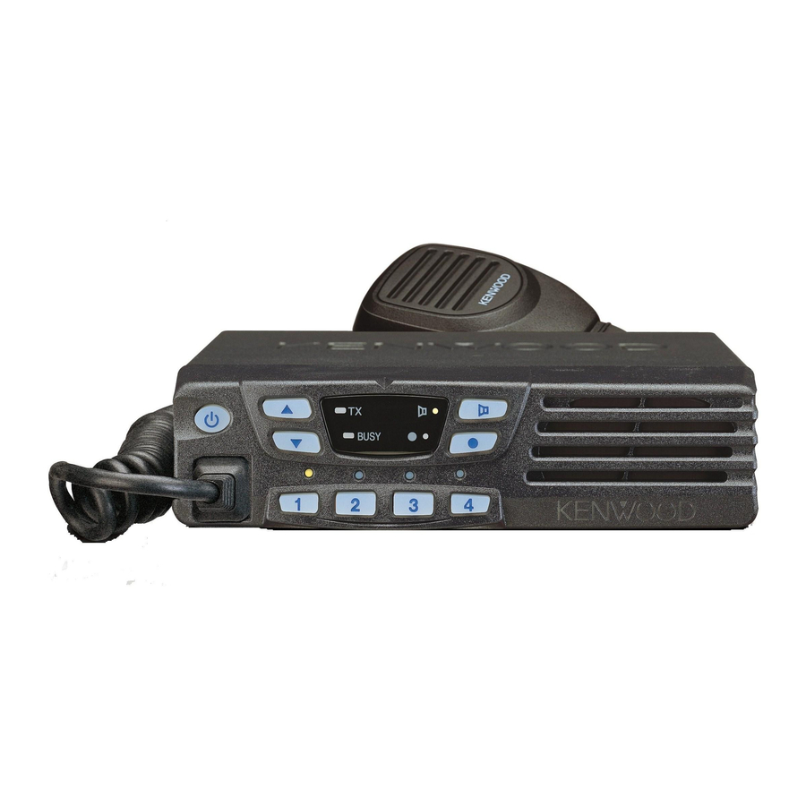
TK-7102 OPERATING FEATURES 1-4. Display 1. Controls and Functions 1-1. Front Panel q w e Indicator Description 1-2. Microphone Light while transmitting. Lights when a signal is detected on the currently selected channel. Li g hts w hi l e t he f u n ct i o n p r o - grammed onto its corresponding key is activated. - Page 5 OPERATING FEATURES • Scan ON/OFF 2. Operation Features Press this key starts scanning. Pressing this key stops The TK-7102 is a VHF FM radio designed to operate in scanning. conventional format. The programmable features are sum- • Talk around marized.
- Page 6 TK-7102 OPERATING FEATURES Temporary delete Clear to transpond It is possible to delete channel temporary during scan. The transceiver waits the transpond of DTMF if channel When scan stops on unnecessary channel for example by is busy until channel open. This feature prevents the inter- interference of the other party, activate the delete function ference to other party.
-
Page 7: Realignment
For group calls, only the group tone will sound, not the transpond tone. 3-2. Connection Procedure 1. Connect the TK-7102 to the personal computer with the Pre alert tone interface cable. Sounds prior to the TOT TX inhibit activation. If TOT pre 2. - Page 8 NOTE: Clone mode should enabled. 1. Turn the master TK-7102 power ON with the [1] key held down. The TK-7102 [ ] LED is turned on. 2. Power on the slave TK-7102.
-
Page 9: Disassembly For Repair
TK-7102 DISASSEMBLY FOR REPAIR 3. To remove the display unit PCB, detach the PCB by 1. When you remove the panel, turn the transceiver up lifting at the indents of the PCB as shown below. side down. Detach the panel by lifting the tabs as shown below. -
Page 10: Circuit Description
TK-7102 CIRCUIT DESCRIPTION IF Amplifier Frequency Configuration The first IF signal is amplified by Q19, and the enters IC5 The receiver utilizes double conversion. The first IF is (FM processing IC). The signal is heterodyned again with a 49.95MHz and the second IF is 450kHz. The first local oscil- second local oscillator signal within IC5 to create a 450kHz lator signal is supplied from the PLL circuit. - Page 11 TK-7102 CIRCUIT DESCRIPTION Wide/Narrow Changeover Circuit Squelch Circuit The Wide port (pin 92) and Narrow port (pin 91) of the The detection output from the FM IF IC (IC5) passes CPU is used to switch between ceramic filters. When the through a noise amplifier (Q18) to detect noise.
- Page 12 TK-7102 CIRCUIT DESCRIPTION IC1 : PLL IC TX VCO RF AMP 5kHz/6.25kHz BUFF D10,12 Phase Charge comparator pump DATA RX VCO Q7,12 T/R SW 5kHz/6.25kHz D9,11 16.8MHz Fig. 6 PLL circuit Unlock Circuit Transmitter System During reception, the 8RC signal goes high, the 8TC sig- Outline nal goes low, and Q29 turns on.
- Page 13 Key Matrix Circuit 2) Adjusts the AF signal level of the AF filter (IC10) and turns The TK-7102 front panel has function keys. Each of them the filter select compounder on or off. is connected to a cross point of a matrix of the KMI1 to 3) Controls the DTMF decoder (IC9).
- Page 14 TK-7102 CIRCUIT DESCRIPTION Encode D/A Converter The QT and DQT signals are output from QT/DQT of the The D/A converter (IC3) is used to adjust MO modulation, CPU (IC6) and summed with the external pin DI line by the AF volume, TV voltage, FC reference voltage, and PC summing amplifier (IC4) and the resulting signal goes to the POWER CONTROL voltage level.
-
Page 15: Semiconductor Data
TK-7102 SEMICONDUCTOR DATA Microprocessor : 784214AGCXXX (TX-RX Unit IC6) Terminal function Pin No. Name Function Pin No. Name Function FNC8 Function Port8 DTMOSC DTMF IC Clock Control PLLE PLL IC Chip Select MUTE1 AF Mute EVLLD E-Volume LD MUTE2 Speaker Mute... -
Page 16: Description Of Components
TK-7102 DESCRIPTION OF COMPONENTS Display Unit (X54-3340-20) Ref. No. Use/Function Operation/Condition DIODE APC VOLTAGE DETECT SYMBOL PARTS NAME DISCRIPTION DIODE APC VOLTAGE DETECT D1~4 KEY BACKLIT DIODE REVERSE CONNECT PROTECTION MONITOR KEY LIGHT DIODE OVER VOLTAGE DETECTION PROGRAMMABLE KEY LIGHT... - Page 17 TK-7102 DESCRIPTION OF COMPONENTS Ref. No. Use/Function Operation/Condition TRANSISTOR DC SWITCH(SB) /Active when power on TRANSISTOR AF MUTE /Active while Mute3 is H TRANSISTOR BEAT SHIFT /Active while Beat shift is on TRANSISTOR OVER VOLTAGE DETECTION /Active while PS voltage is more than 18V...
-
Page 18: Parts List
TK-7102 PARTS LIST New Parts. indicates safety critical components. Parts without Parts No. are not supplied. Les articles non mentionnes dans le Parts No. ne sont pas fournis. Teile ohne Parts No. werden nicht geliefert. TX-RX UNIT (X57-6290-20) TK-7102 Ref. No. - Page 19 TK-7102 PARTS LIST TX-RX UNIT (X57-6290-20) Ref. No. Address Parts No. Description Destination Ref. No. Address Parts No. Description Destination parts parts CC73GCH1H101J CHIP C 100PF C180 CK73GB1H103J CHIP C 0.010UF J CC73GCH1H050B CHIP C 5.0PF C182 CK73GB1C104K CHIP C 0.10UF...
- Page 20 TK-7102 PARTS LIST TX-RX UNIT (X57-6290-20) Ref. No. Address Parts No. Description Destination Ref. No. Address Parts No. Description Destination parts parts C274 CK73GB1H103K CHIP C 0.010UF K C379 CK73GB1C104K CHIP C 0.10UF C508 CK73GB1H102K CHIP C 1000PF C275 CK73GB1C104K CHIP C 0.10UF...
- Page 21 TK-7102 PARTS LIST TX-RX UNIT (X57-6290-20) Ref. No. Address Parts No. Description Destination Ref. No. Address Parts No. Description Destination parts parts L41-1085-06 SMALL FIXED INDUCTOR RK73GB1J223J CHIP R J 1/16W L92-0140-05 FERRITE CHIP RK73GB1J473J CHIP R J 1/16W L77-1868-05 TCXO (16.8MHZ)
- Page 22 TK-7102 PARTS LIST TX-RX UNIT (X57-6290-20) Ref. No. Address Parts No. Description Destination Ref. No. Address Parts No. Description Destination parts parts R158 RK73GB1J102J CHIP R 1.0K J 1/16W R229 RK73GB1J223J CHIP R J 1/16W R159,160 RK73GB1J101J CHIP R J 1/16W...
- Page 23 TK-7102 PARTS LIST TX-RX UNIT (X57-6290-20) Ref. No. Address Parts No. Description Destination Ref. No. Address Parts No. Description Destination parts parts R313 RK73GB1J821J CHIP R J 1/16W IC20 KIA7808AF ANALOG IC IC21 NJM2100V MOS IC R316 R92-1252-05 CHIP R...
-
Page 24: Exploded View
TK-7102 EXPLODED VIEW N67-3008-46 PAN HEAD SEMS SCREW N87-2606-46 BRAZIER HEAD TAPTITE SCREW N87-2614-46 BRAZIER HEAD TAPTITE SCREW (For KEY 1 only) DISPLAY UNIT TX-RX UNIT Parts with the exploded numbers larger than 700 are not supplied. -
Page 25: Packing
TK-7102 PACKING 25 Bracket D SCREW SET (J29-0662-03) (N99-0395-05) 8 DC cord (E30-3339-05) Protection bag (H25-0103-04) 19 Inner Packing Case (H02-0617-02) 5 Instruction Manual (B62-1389-00) 20 Polystyrene Foamed Fixture 21 Polystyrene Foamed Fixture (H10-6636-03) (H10-6639-03) Protection Bag (H25-2320-04) 24 Item Carton Case (H52-1699-02) Parts with the exploded numbers larger than 700 are not supplied. -
Page 26: Adjustment
TK-7102 ADJUSTMENT Test Equipment Required for Alignment Test Equipment Major Specifications 1. Standard Signal Generator Frequency Range 140 to 175MHz (SSG) Modulation Frequency modulation and external modulation Output –127dBm/0.1 V to greater than –7dBm/100mV 2. Power Meter Input Impedance Operation Frequency... - Page 27 TK-7102 ADJUSTMENT Note Adjustment Location • EEPROM Switch The tuning data (Deviation, Squelch, etc.) for the EEPROM, is stored in memory. When parts are changed, Volume readjust the transceiver. up/down Power Display PF key • AF PA IC (IC102) How to mounting the IC102.
-
Page 28: Receiver Section
TK-7102 ADJUSTMENT Use KPG-70D programming software for adjustment of the next items. PCB Section Measurement Adjustment Specifications/ Item Condition Test equipment Terminal Parts Method Remarks 1. Setting 1) Power supply voltage DC Power supply teriminal:13.6V 2. VCO lock 1) CH: TX high Digital voltmeter 5.5V... - Page 29 TK-7102 ADJUSTMENT Transmitter section Measurement Adjustment Specifications/ Item Condition Test equipment Terminal Parts Method Remarks 1. Frequency 1) CH: TX center Frequency PC key Adjust to center frequency within 100Hz 2) Transmit counter 2. High power 1) CH: TX low Power meter 1.0W...
- Page 30 TK-7102 ADJUSTMENT BPF-Wave Fig. 1 TK-260 :K, K2...
-
Page 31: Pc Board Views
TK-7102 PC BOARD VIEW DISPLAY UNIT (X54-3340-20) Component side view + Foil side view DISPLAY UNIT (X57-3340-20) Component side view MONI POWER HOOK DOWN PROG POWER LEDMON LEDPF LEDC1 LEDC2 LEDR LEDG MICBL LEDC3 LEDC4 KMI1 KMI2 KMI3 KMI4 KMO1... -
Page 32: Tx-Rx Unit (X57-6290-20)
TK-7102 PC BOARD VIEW TX-RX UNIT (X57-6290-20) Component side view TX-RX UNIT (X57-6290-20) Component side view R262 C323 IC101 C312 R267 C321 C295 R239 C299 R238 R265 C328 C292 Q101 R247 C315 R263 R244 R236 C303 R241 C254 R240 R154... - Page 33 TK-7102 PC BOARD VIEW TX-RX UNIT (X57-6290-20) Foil side view TX-RX UNIT (X57-6290-20) Foil side view C327 R268 C251 R245 C273 R328 R233 C246 C233 R221 C244 C216 C213 C199 C197 C514 R306 R208 R283 C367 C206 C177 R320 C358...
- Page 34 TK-7102 PC BOARD VIEW TX-RX UNIT (X57-6290-20) Component side view + Foil side view TX-RX UNIT (X57-6290-20) Component side + Foil side view C327 R268 R262 C323 IC101 C312 R267 C321 C295 R239 C299 R238 R265 C251 C328 C292 Q101...
-
Page 35: Schematic Diagram
TK-7102 SCHEMATIC DIAGRAM Note : Component marked with a dot ( ) are parts of pattern1. -
Page 36: Block Diagram
TK-7102 TK-7102 BLOCK DIAGRAM... -
Page 37: Level Diagram
TK-7102 TK-7102 LEVEL DIAGRAM RX section TX section... -
Page 38: Terminal Function
TK-7102 TERMINAL FUNCTION CN1 (TX-RX Unit) J1 (TX-RX Unit) Pin No. Name Function Pin No. Name Function Audio signal output to internal/external speaker. Ground Ground PTT/TXD HOOK Hook detection/RXD Mic ground J1 (Control Unit) Mic signal input Pin No. Name... -
Page 39: Specifications
KENWOOD ELECTRONICS TECHNOLOGIES(S) PTE LTD. KENWOOD ELECTRONICS U.K. LIMITED Sales Marketing Division KENWOOD House, Dwight Road, Watford, Herts., WD1 8EB United Kingdom 1 Ang Mo Kio Street 63, Singapore 569110 KENWOOD ELECTRONICS EUROPE B.V. Amsterdamseweg 37, 1422 AC Uithoorn, The Netherlands...
Need help?
Do you have a question about the TK-7102 and is the answer not in the manual?
Questions and answers