Kenwood TK-7102H Service Manual
Vhf fm transceiver
Hide thumbs
Also See for TK-7102H:
- Service manual (43 pages) ,
- Instruction manual (16 pages) ,
- Specification (2 pages)
Table of Contents
Advertisement
VHF FM TRANSCEIVER
TK-7102H
SERVICE MANUAL
Chassis
(A10-4048-11)
GENERAL .................................................. 2
OPERATING FEATURES .......................... 3
REALIGNMENT ......................................... 7
DISASSEMBLY FOR REPAIR ................... 9
CIRCUIT DESCRIPTION .......................... 10
SEMICONDUCTOR DATA ...................... 15
DESCRIPTION OF COMPONENTS ........ 17
PARTS LIST ............................................. 19
EXPLODED VIEW .................................... 25
PACKING ................................................. 26
Cabinet
Front glass
(A01-2181-01)
(B10-2668-03)
Modular jack
Key top
(E08-0877-05)
(K29-9065-01)
CONTENTS
ADJUSTMENT ........................................ 27
TERMINAL FUNCTION ........................... 32
SCHEMATIC DIAGRAM .......................... 41
BLOCK DIAGRAM ................................... 45
LEVEL DIAGRAM .................................... 47
SPECIFICATIONS .................................... 49
© 2001-11 PRINTED IN JAPAN
B51-8610-00 ( N ) 1051
Panel assy
(A62-0942-03)
DISPLAY UNIT (X54-3340-20) ............ 33
TX-RX UNIT (X57-6380-20) ................ 35
Advertisement
Table of Contents

Related Manuals for Kenwood TK-7102H


Summary of Contents for Kenwood TK-7102H
-
Page 1: Table Of Contents
VHF FM TRANSCEIVER TK-7102H SERVICE MANUAL © 2001-11 PRINTED IN JAPAN B51-8610-00 ( N ) 1051 Chassis Cabinet Front glass Panel assy (A10-4048-11) (A01-2181-01) (B10-2668-03) (A62-0942-03) Modular jack Key top (E08-0877-05) (K29-9065-01) CONTENTS GENERAL ..........2 ADJUSTMENT ........27 OPERATING FEATURES ......3 TERMINAL FUNCTION ...... -
Page 2: General
TK-7102H GENERAL 3. PRE-INSTALLATION CHECKOUT INTRODUCTION 3-1. Introduction SCOPE OF THIS MANUAL Each radio is adjusted and tested before shipment. How- This manual is intended for use by experienced techni- ever, it is recommended that receiver and transmitter opera- cians familiar with similar types of commercial grade com- tion be checked for proper operation before installation. -
Page 3: Operating Features
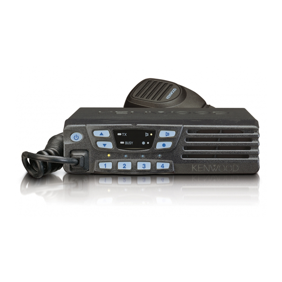
Control station. The antenna system selection depends 1. Controls and Functions on many factors and is beyond the scope of this manual. Your KENWOOD dealer can help you select an antenna sys- 1-1. Front Panel tem that will best serve your particular needs. - Page 4 TK-7102H OPERATING FEATURES 1-4. Display 2. Operation Features The TK-7102H is a VHF FM radio designed to operate in conventional format. The programmable features are sum- marized. 3. Transceiver Controls and Indicators 3-1. Front Panel Controls All the keys on the front panel are momentary-type push buttons.
-
Page 5: Scan Operating
TK-7102H OPERATING FEATURES • Key lock Revert channel Pressing this key causes the transceiver to accept entry The revert channel is used to transmit during scanning of only the [Vol Up/Down]*, [Key lock], Microphone [PTT], and set by the programming software (KPG-70D). -
Page 6: Audible User Feedback Tones
TK-7102H OPERATING FEATURES Off hook decode SP unmute Channel setting RX condition Speaker If the Off hook decode function has been enabled, re- QT/DQT DTMF condition moving and replacing the microphone on the hook has no Carrier None None Carrier Sounds effect for decoding QT/DQT and option signalling. -
Page 7: Realignment
PTT key is released. 3. PC Mode 3-1. Preface The TK-7102H transceiver is programmed using a per- sonal computer, a programming interface (KPG-46) and pro- gramming software (KPG-70D). The programming software can be used with an IBM PC or compatible. -
Page 8: Clone Mode
When data is received by the transceiver, the green LED blink. 1. Turn the master TK-7102H power ON with the [1] key In the PC mode, 4CH LEDs, [MON] LED and [ ] LED are held down. The TK-7102H [ ] LED is turned on. -
Page 9: Disassembly For Repair
TK-7102H DISASSEMBLY FOR REPAIR 3. To remove the display unit PCB, detach the PCB by lifting 1. When you remove the panel, turn the transceiver up side down. Detach the panel by lifting the tabs as shown be- at the indents of the PCB as shown below. -
Page 10: Circuit Description
TK-7102H CIRCUIT DESCRIPTION Frequency Configuration Item Rating Nominal center frequency 49.95MHz The receiver utilizes double conversion. The first IF is 49.95MHz and the second IF is 450kHz. The first local oscil- Pass bandwidth 5.0kHz or more at 3dB lator signal is supplied from the PLL circuit. - Page 11 TK-7102H CIRCUIT DESCRIPTION CF1 (Wide) CF2 (Narrow) L36,38 L30,32 D801 D25,26 D21,22 D804 RF AMP IF AMP D/A CONVERTER IF system IC23 1/2 divider TCXO X3 multiply 1st local OSC (VCO/PLL) Fig. 2 Receiver system Wide/Narrow Changeover Circuit AF Signal System...
- Page 12 TK-7102H CIRCUIT DESCRIPTION Unlock Circuit PLL Frequency Synthesizer During reception, the 8RC signal goes high, the 8TC sig- The PLL circuit generates the first local oscillator signal nal goes low, and Q29 turns on. Q31 turns on and a voltage for reception and the RF signal for transmission.
- Page 13 TK-7102H CIRCUIT DESCRIPTION Transmitter System Control Circuit Outline The CPU carries out the following tasks: 1) Controls the WIDE, NARROW, TX/RX outputs. The transmitter circuit produces and amplifies the de- 2) Adjusts the AF signal level of the AF filter (IC10) and turns sired frequency directly.
- Page 14 IC11(2/2) IC11(1/2) Key Matrix Circuit QTIN The TK-7102H front panel has function keys. Each of them is connected to a cross point of a matrix of the KMI1 to KMO2 ports of the microprocessor. The KMO1 to KMO2 DTMF ports are always high, while the KMI1 to KMI4 ports are al- DECO.
-
Page 15: Semiconductor Data
TK-7102H CIRCUIT DESCRIPTION / SEMICONDUCTOR DATA SEMICONDUCTOR DATA Power Supply Circuit When the POWER switch on the display unit is pressed, Microprocessor : 784214AGCXXX the power port on the display unit which is connected to CPU port 18 (POWER), goes low, then CPU port 93 (SBC) - Page 16 TK-7102H SEMICONDUCTOR DATA Pin No. Name Function Pin No. Name Function AVREF LEDC1 LED for CH1 Key FNC1 Function Port 1 LEDC2 LED for CH2 Key FNC2 Function Port 2 LEDR TX LED HOOK Hook LEDG Busy LED From FPU...
-
Page 17: Description Of Components
TK-7102H DESCRIPTION OF COMPONENTS Display Unit (X54-3340-20) Ref. No. Parts Name Description Ref. No. Parts Name Description Diode Reverse connect protection D1~4 Key backlit Diode Over voltage detection Monitor key light Poly switch Current protection Programmable key light Diode OR gate /MIC mute, AGC... - Page 18 TK-7102H DESCRIPTION OF COMPONENTS Ref. No. Parts Name Description Ref. No. Parts Name Description Transistor DC switch (8R) PLL synthesizer / Active while RX D/A converter Transistor AF mute Buffer amplifier / SUM amplifier / Active while MUTE2 is H...
-
Page 19: Parts List
TK-7102H PARTS LIST New Parts. indicates safety critical components. L : Scandinavia K : USA P : Canada Parts without Parts No. are not supplied. Y : PX (Far East, Hawaii) T : England E : Europe Les articles non mentionnes dans le Parts No. ne sont pas fournis. - Page 20 TK-7102H PARTS LIST TX-RX UNIT (X57-6380-20) Desti- Desti- Ref. No. Address Parts No. Description Ref. No. Address Parts No. Description parts nation parts nation CC73GCH1H271J CHIP C 270PF C176 CK73GB1H102K CHIP C 1000PF CK73GB1H471K CHIP C 470PF C177 CC73GCH1H220J CHIP C...
- Page 21 TK-7102H PARTS LIST TX-RX UNIT (X57-6380-20) Desti- Desti- Ref. No. Address Parts No. Description Ref. No. Address Parts No. Description parts nation parts nation C307 CK73GB1H102K CHIP C 1000PF C835 C93-0603-05 CHIP C 1000PF 500WV C308 C92-0560-05 CHIP-TAN 10UF 6.3WV...
- Page 22 TK-7102H PARTS LIST TX-RX UNIT (X57-6380-20) Desti- Desti- Ref. No. Address Parts No. Description Ref. No. Address Parts No. Description parts nation parts nation L800,801 L41-2775-06 SMALL FIXED INDUCTOR RK73GB1J103J CHIP R 1/16W L802 L34-4608-05 AIR-CORE COIL RK73GB1J473J CHIP R...
- Page 23 TK-7102H PARTS LIST TX-RX UNIT (X57-6380-20) Desti- Desti- Ref. No. Address Parts No. Description Ref. No. Address Parts No. Description parts nation parts nation R159,160 RK73GB1J101J CHIP R 1/16W R242 RK73GB1J472J CHIP R 4.7K 1/16W R161 RK73GB1J473J CHIP R 1/16W...
- Page 24 TK-7102H PARTS LIST TX-RX UNIT (X57-6380-20) Desti- Desti- Ref. No. Address Parts No. Description Ref. No. Address Parts No. Description parts nation parts nation R811 R92-1215-05 CHIP R 1/2W 2SC4649(N,P) TRANSISTOR R812,813 RK73GB1J473J CHIP R 1/16W 2SA1832(GR) TRANSISTOR R814 RK73GB1J563J...
-
Page 25: Exploded View
TK-7102H EXPLODED VIEW M2.6 x 8 : N67-2608-46 M2.6 x 6 (Br-Tap) : N87-2606-46 M2.6 x 14 (Br-Tap) : N87-2614-46 Bx2 Bx2 IC101 Q101 DISPLAY UNIT (X54) TX-RX UNIT (X57) Parts with the exploded numbers larger than 700 are not supplied. -
Page 26: Packing
TK-7102H PACKING 36 Protection bag (H25-2341-04) 6 Instruction manual (English) (B62-1596-00) 7 Instruction manual (Spanish) (B62-1597-00) : K 34 Packing fixture (H12-3112-05) 34 Packing fixture (H12-3112-05) 36 Protection bag (H25-2341-04) 47 Microphone (T91-0624-05) : K 37 Item carton case (H52-1829-12) -
Page 27: Adjustment
TK-7102H ADJUSTMENT Test Equipment Required for Alignment Test Equipment Major Specifications 1. Standard Signal Generator Frequency Range 136 to 175MHz (SSG) Modulation Frequency modulation and external modulation Output –127dBm/0.1 V to greater than –7dBm/100mV 2. Power Meter Input Impedance Operation Frequency... - Page 28 TK-7102H ADJUSTMENT Note Adjustment Location • EEPROM Switch The tuning data (Deviation, Squelch, etc.) for the Power Display EEPROM, is stored in memory. When parts are changed, Volume readjust the transceiver. up/down Speaker • AF PA IC (IC101) How to mounting the IC101.
- Page 29 TK-7102H ADJUSTMENT 5. The solder melts and binds the FET and the cube se- Replacing a Drive FET (Q800) curely. Then, slide the soldering iron along the PCB sur- 1. When replacing the Drive FET, you must also replace its face to cool the soldering down ( r ).
- Page 30 TK-7102H ADJUSTMENT PCB Section Measurement Adjustment Specifications/ Item Condition Remarks Test equipment Terminal Parts Method 1. Setting 1) Power supply voltage DC Power supply terminal : 13.6V 2. VCO lock 1) CH : TX high Digital voltmeter 5.5V 0.1V voltage* 2) CH : RX high 5.5V...
- Page 31 TK-7102H ADJUSTMENT Transmitter Section Measurement Adjustment Specifications/ Item Condition Remarks Test equipment Terminal Parts Method 1. Frequency 1) CH : TX center Frequency counter PC key Adjust to center frequency Within 100Hz 2) Transmit 2. High 1) CH : TX low Power meter 1.0W...
-
Page 32: Terminal Function
TK-7102H TERMINAL FUNCTION CN1 (TX-RX Unit) J1 (TX-RX Unit) Pin No. Name Function Pin No. Name Function Ground Audio signal output to internal/external speaker. PTT/TXD Ground HOOK Hook detection/RXD J1 (Control Unit) Mic ground Mic signal input Pin No. Name... -
Page 33: Pc Board Views
TK-7102H PC BOARD VIEWS DISPLAY UNIT (X54-3340-20) Component side view KRC404RTK DA221 NJM2100V KRC414RTK NJM2904V UPB1509GV 2SA1745 2SA1832 24LC08BT-ISN 2SC2412K MONI 2SC4617 MA742 2SC4738 2SC5108 POWER TA75W01FU 2SK508NV HOOK DOWN PROG POWER 2SC3357 LEDMON LEDPF LEDC1 LEDC2 LEDR LEDG MICBL... -
Page 34: Tx-Rx Unit (X57-6380-20)
TK-7102H PC BOARD VIEW TX-RX UNIT (X57-6380-20) Component side view Ref. No. Address R262 IC17 C852 IC19 IC21 C295 C350 IC22 C299 C829 R265 IC101 C849 C328 C853 R154 IC800 C827 C811 Q800 C843 C812 Q101 C839 C808 R805 C283... - Page 35 TK-7102H PC BOARD VIEW TX-RX UNIT (X57-6380-20) Foil side view Ref. No. Address IC10 IC11 IC14 IC15 L809 IC18 IC20 IC23 C850 C846 R823 D806 C841 C840 L807 D805 L805 C837 C832 C247 R821 C836 C213 C199 C216 C197 C514...
- Page 36 TK-7102H PC BOARD VIEW TX-RX UNIT (X57-6380-20) Component side view + Foil side Ref. No. Address Ref. No. Address R262 C852 L809 C295 C350 IC10 C299 C829 R265 IC11 C849 C328 R154 C853 IC14 Q101 C827 C850 C846 IC15 Q800...
-
Page 37: Schematic Diagram
TK-7102H Note : Component marked with a dot ( ) are parts of pattern 1. SCHEMATIC DIAGRAM... -
Page 38: Block Diagram
TK-7102H TK-7102H BLOCK DIAGRAM... -
Page 39: Level Diagram
TK-7102H TK-7102H LEVEL DIAGRAM Receiver Section Transmitter Section... -
Page 40: Specifications
TK-7102H SPECIFICATIONS GENERAL Frequency Range ....... 146 to 174MHz Number of Channels ......4 channels Channel Spacing ......... Wide : 25kHz Narrow : 12.5kHz PLL Channel Stepping ......2.5, 5, 6.25, 7.5kHz Operating Voltage ....... 13.6V DC 15% Current Drain ........Less than 0.4A on standby Less than 1.0A on receive... - Page 41 Leuvensesteenweg 248 J, 1800 Vilvoorde, Belgium KENWOOD ELECTRONICS FRANCE S.A. 13, Boulevard Ney, 75018 Paris, France KENWOOD ELECTRONICS U.K. LIMITED KENWOOD House, Dwight Road, Watford, Herts., WD1 8EB United Kingdom KENWOOD ELECTRONICS EUROPE B.V. Amsterdamseweg 37, 1422 AC Uithoorn, The Netherlands KENWOOD ELECTRONICS ITALIA S.p.A.
Need help?
Do you have a question about the TK-7102H and is the answer not in the manual?
Questions and answers